7/27/15: Teak Rails (part I)
The following diagram is a doctored-up clipping of the original deck layout plans. It shows cross sections of the teak rubrail, toerail, and cap. The rubrail has a near-triangular cross section and extends most of the length of the boat. Not all of the RR/O40 sisterships have a rubrail, and Thalassa’s might have been a custom job. The rubrail is bolted through the hull about every 8″ and is quite substantial. It provides excellent protection from pilings and other boats and surely adds significant structural strength to the hull.
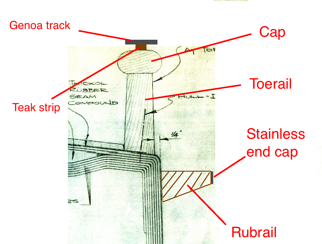
The toerail extends all the way around, and cross-sectional shape varies in a very complex way: The bottom end is 1/4″ wider then then top, and the height is always parallel to the topsides, but the topsides are not everywhere perpendicular to the deck (at deck level, the topsides are relatively vertical amidships and aft, but there is a prominent outward flare toward the bow). Moreover, the toerail is higher at the bow than the stern, and the cap is always horizontal.
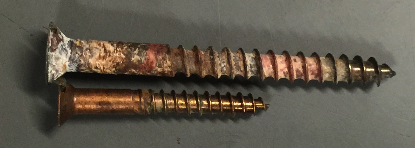
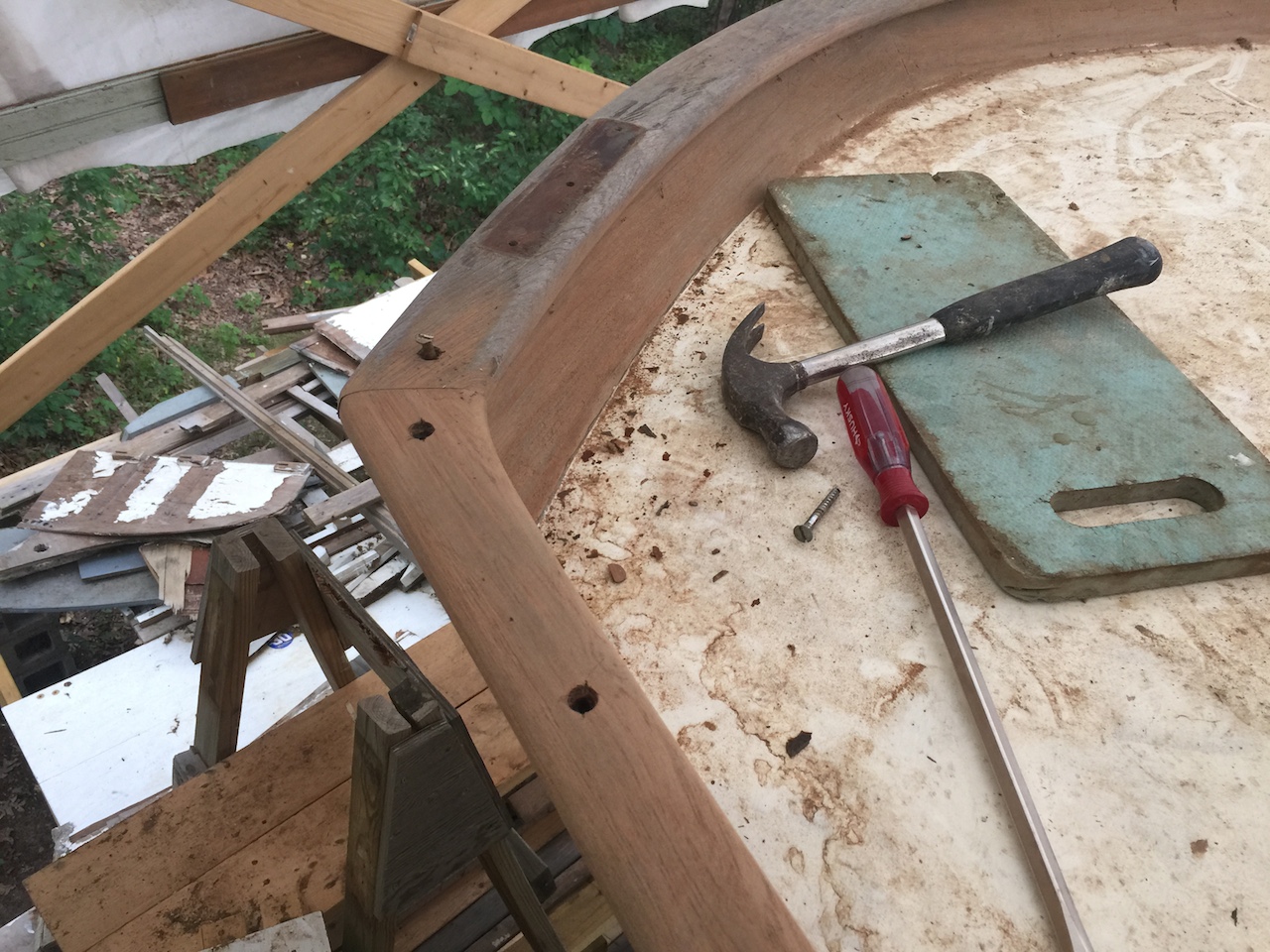
The toreail is bolted hrough the hull about every 8″ and the cap is screwed to the toerail about every 8″. The genoa tracks are about 15 feet in length, and are screwed into the cap and toerail about every 4″. The longer screw in the following photo held a genoa track down, while the shorter screw fastened the cap.
If the toerail bolts are in poor condition (rusty/corroded), then it might be necessary to remove the toerail and replace the bolts. Salvaging the toerail during this process would be very challenging, and in the worst case it would necessary to fabricate a completely new toerail.
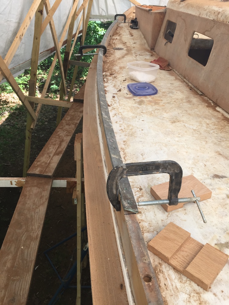
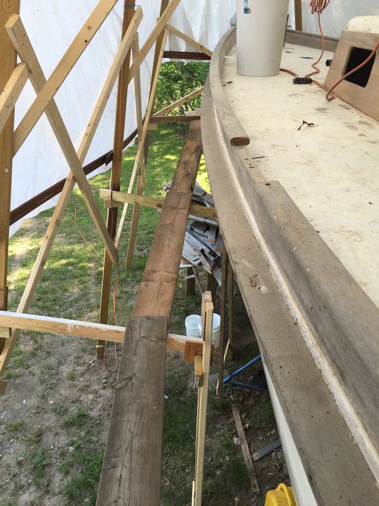
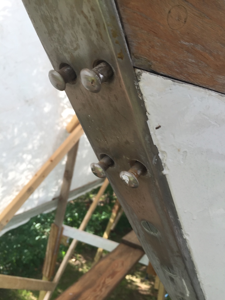
To access the toerail bots for inspection, three short sections of the cap were removed at various locations around the hull (the photo below shows one such section). Four bolts were removed, and they were found to be completely free or rust, corrosion, or any sign of deterioration.
The next question was whether or not to remove and replace the cap. Unlike the toerail, the cap has a uniform cross section all the way around (except for where it terminates at the bow and stern), with a simple, oval shape that can be milled easily with a router. There are several disadvantages to removing the cap:
(1) The cost of the new wood and fasteners
(2) The labor required
There are several advantages to removing and replacing the cap:
(1) The three short pieces that have been cut away must be replaced anyway. Either splicing in the old pieces or milling up new pieces will require labor.
(2) Sanding the toerail would be much easier without the cap. Only a detail sander fits into the space under the cap, and achieving a smooth, uniform finish will be very difficult.
(3) A third advantage was discovered while removing the genoa tracks. So many of the bronze screws broke off, that it would be necessary to move the genoa tracks so that the new screws could be sunk into fresh wood. Now, without removing the cap, the precise locations of the torail screws would be unknown, so determining the new location of the genoa tracks would be impossible.
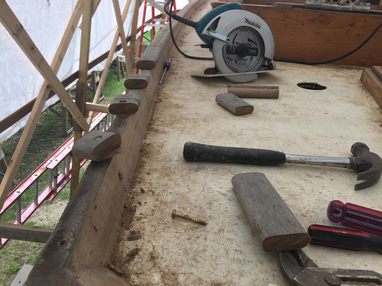
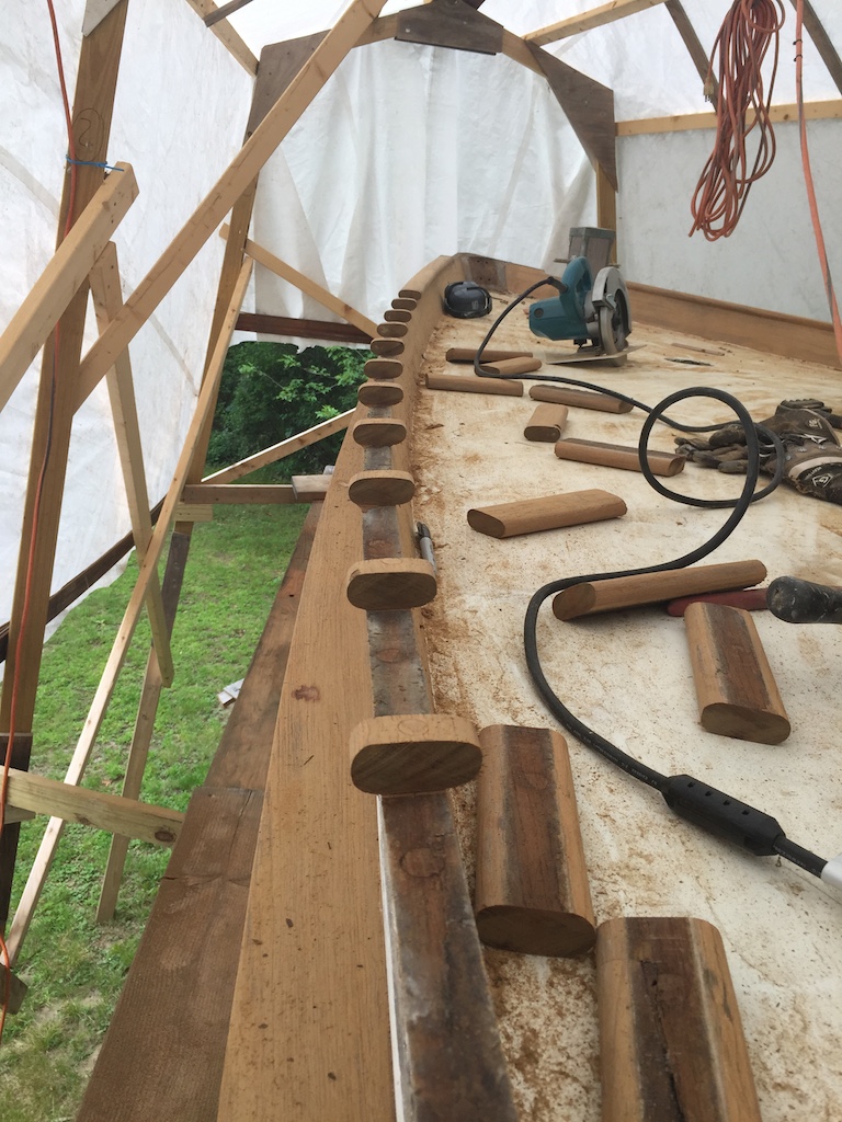
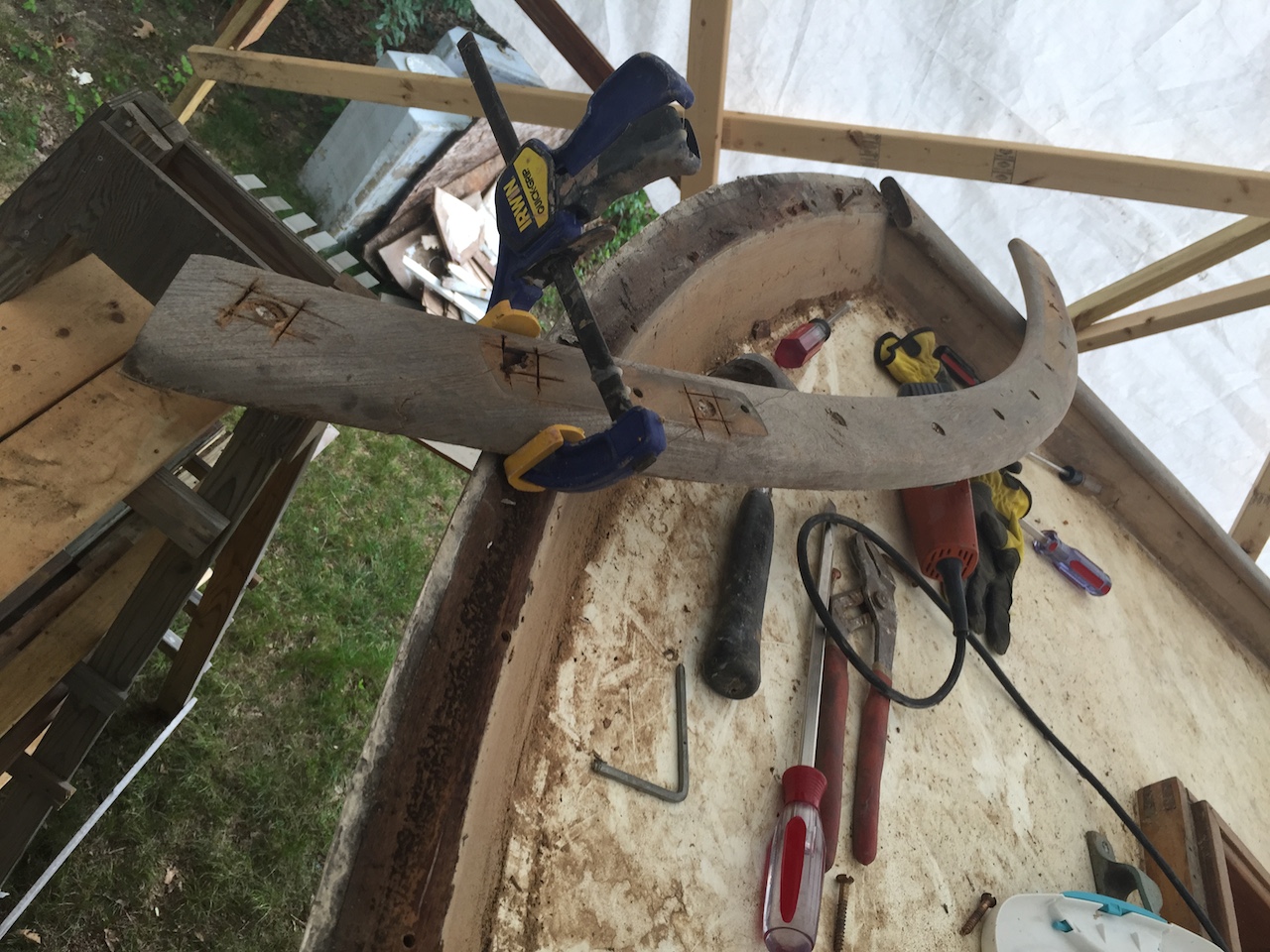
Point (3) thus tipped the scales in favor of removing and replacing the cap. The procedure employed for removal was to use a circular saw, whose depth was set to the height of the cap, to cut around the cap screws and then remove the screws (either by turning the remaining wood or chiseling it away and using a screwdriver or heavy pliers). The following two photos show some of this process underway.
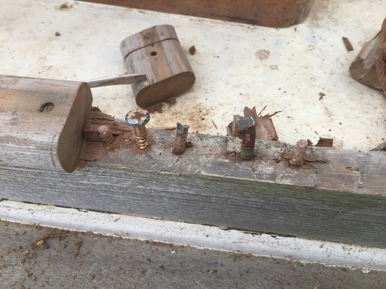
The next two photos shows some of the broken screws.
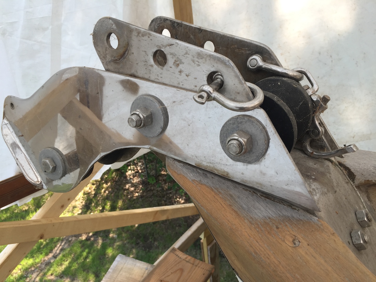
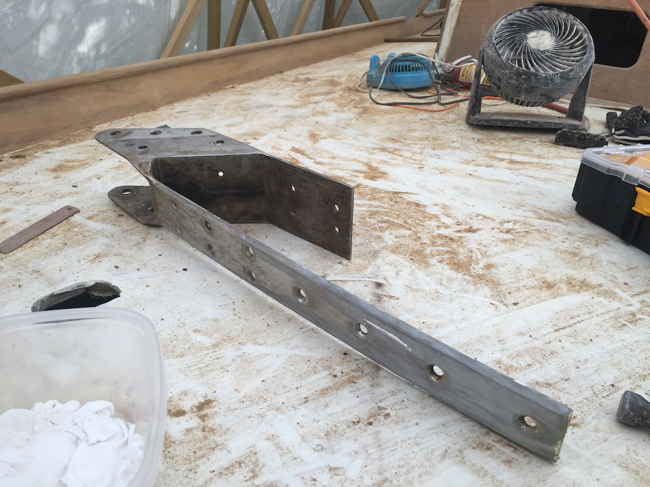
This job was a good excuse to remove the stemhead fitting, as illustrated in the following photos.
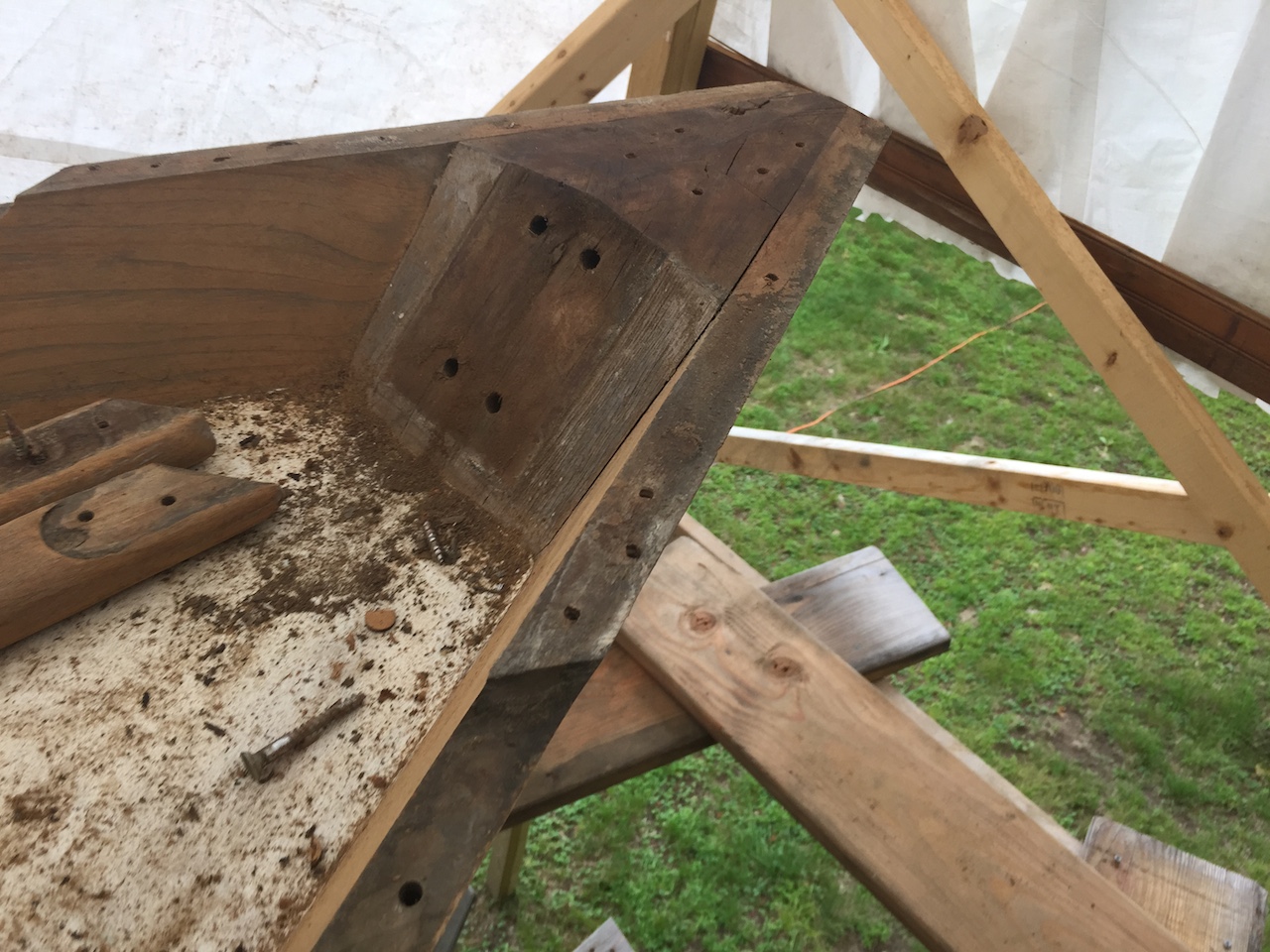
The cap is shaped differently at the fore and aft ends, so these pieces were saved to be used as templates for fabricating new pieces. The following photo shows the aft pieces before and after removal.
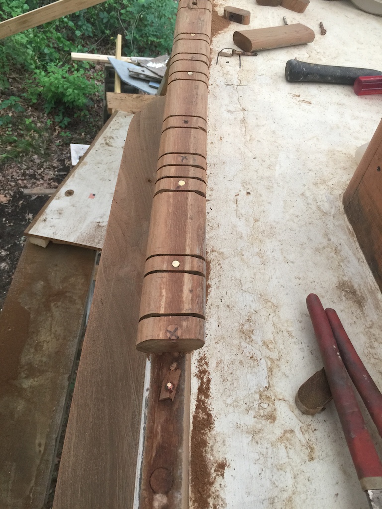
With the cap removed, it was time to address the new location for the genoa tracks. While sailing, the genoa tracks didn’t seem to extend forward enough, and the aft few feet seemed unnecessary, so the plan was to try a location a few feet forward. A grinder was used to level the broken screws and the positions of the toerail bolts were marked in black, as shown in the following photo.
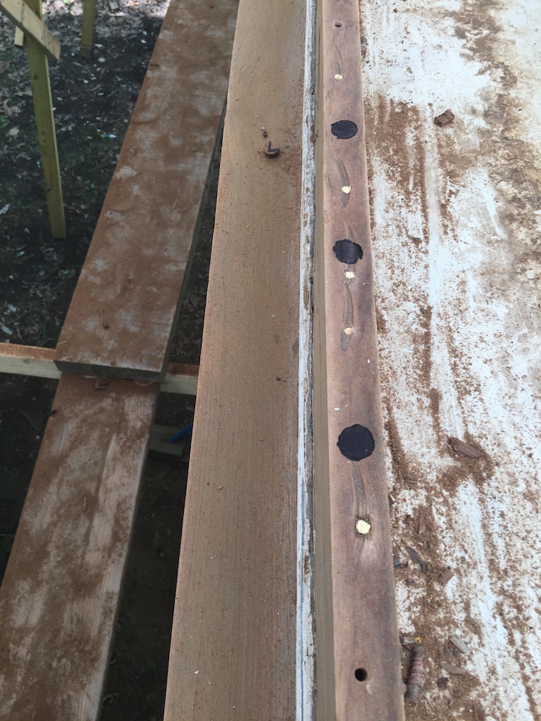
The following photo shows the starboard genoa track laid on the capless toe rail. With surprisingly little fuss, a position was found where none of the screw holes in the genoa track lined up with any of the broken-off screws or toerail bolts in the toerail. The same will be done on the port side before moving on to the restoration of the toerail and rubrail.