4/4/2016: Modifications Discussion, Bulkheads, Scarf Jig/Joints
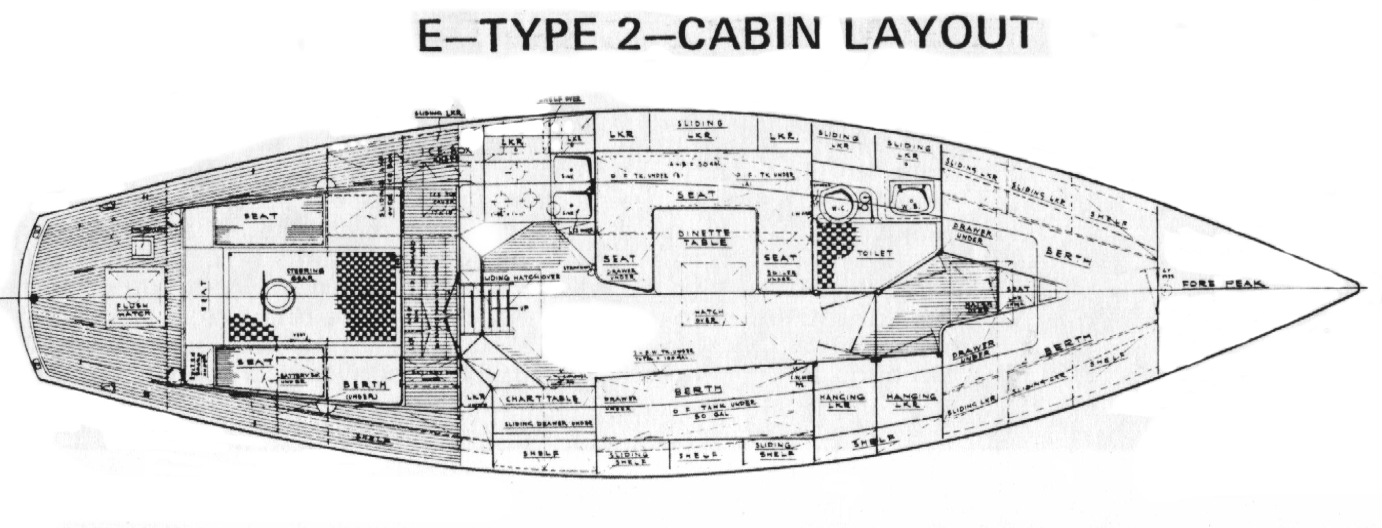
The Offshore 40 was available in a variety of cabin layouts (see the page titled “The Boat” for details), and Cheoy Lee would make custom modifications on the buyer’s request. The following image shows the “E-type 2-cabin” layout, and Thalassa’s original owner ordered this layout, but with the port-side dinette and table replaced by a port berth and a folding table amidships, and the starboard quarter berth converted into a wet storage area.
As we have seen, Thalassa was gutted completely, so major modifications are possible during the rebuilt. The following image shows two marked-up pieces of the previous image (these diagrams were created using a simple paint program). The diagram on the left shows the original head area and forward cabin. The red lines are bulkheads, the green lines are doors, and the yellow lines are doors to hanging lockers. Doors lead into the head from the main cabin and forward cabin, and a door separates the main cabin from the forward cabin. The black dot at the intersection of the three doors is the forward compression post. Thalassa’s head was fairly spacious, as sailboat heads go, but it was still cramped. Note that the head is angled so that the legs of a sitting crewmember will swing forward, away from the main bulkhead. This angling was not an aesthetic choice, but a means to keep the crewmembers right leg from squishing into the main bulkhead while sitting on the toilet.
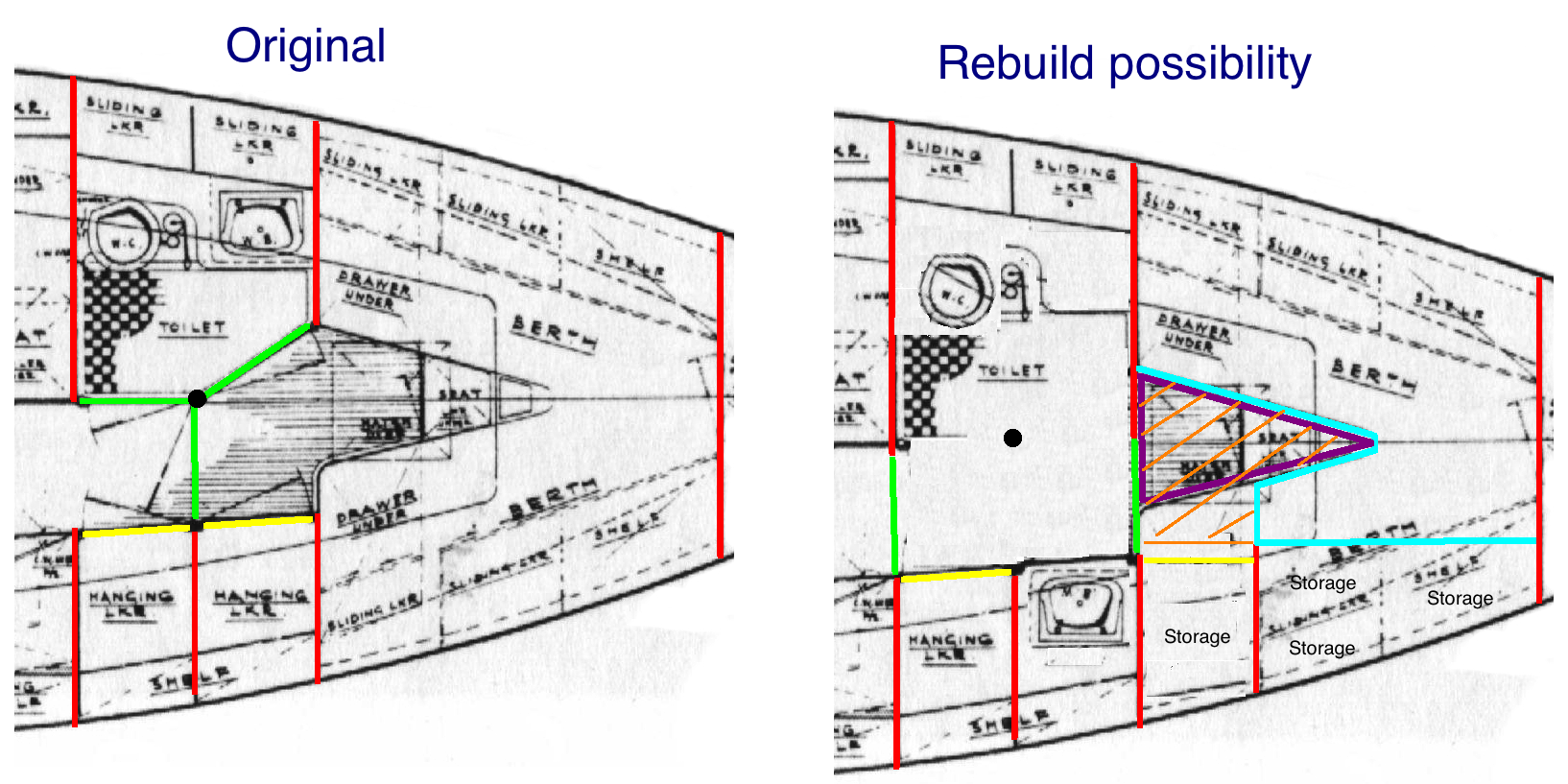
The diagram on the right shows a rebuild possibility that expands the size of the head are to practically decadent proportions. Note the changes: (1) The forward, port bulkhead is wider, creating a door-sized opening to the forward cabin. (2) There is now one door into the head from the main cabin and one into the head from the forward cabin. (3) The toilet is moved forward and slightly inboard. (4) The forward cabin is no longer a natural double-berth, but would be so only with a cushion insert.
The improvements to the head are mostly self-evident. The compression post provides not only a convenient (and necessary) hand hold, but perhaps somewhere to mount a removable shower head and hose that can be stowed when not in use. The toilet is much more comfortable, with more leg and elbow room. The sink area has more counter space and more storage space above, below, and behind. The former sink area can be extended amidships to create storage. The spaciousness creates a much more comfortable atmosphere, which makes using the head a much less intimidating prospect for guests who might not be used to life aboard.
The overall utility of the forward cabin has not been sacrificed by these changes. Losing some floorspace to the head area is offset by removing the step/seat. The area in the purple triangle outlines the floorspace. The reduced berth area is problematic only if the forward cabin will be used by two people not accustomed to sleeping side-by-side. The cushion insert will cover the area hatch-marked in orange, and provide a generous double berth that no less impossible to climb into than in the original layout when the V-shaped insert was installed. The areas marked “storage” on the starboard side will include drawers, sliding lockers, and some countertop space for loose items.
This discussion could go on, but let’s get back to describing the most recent projects.
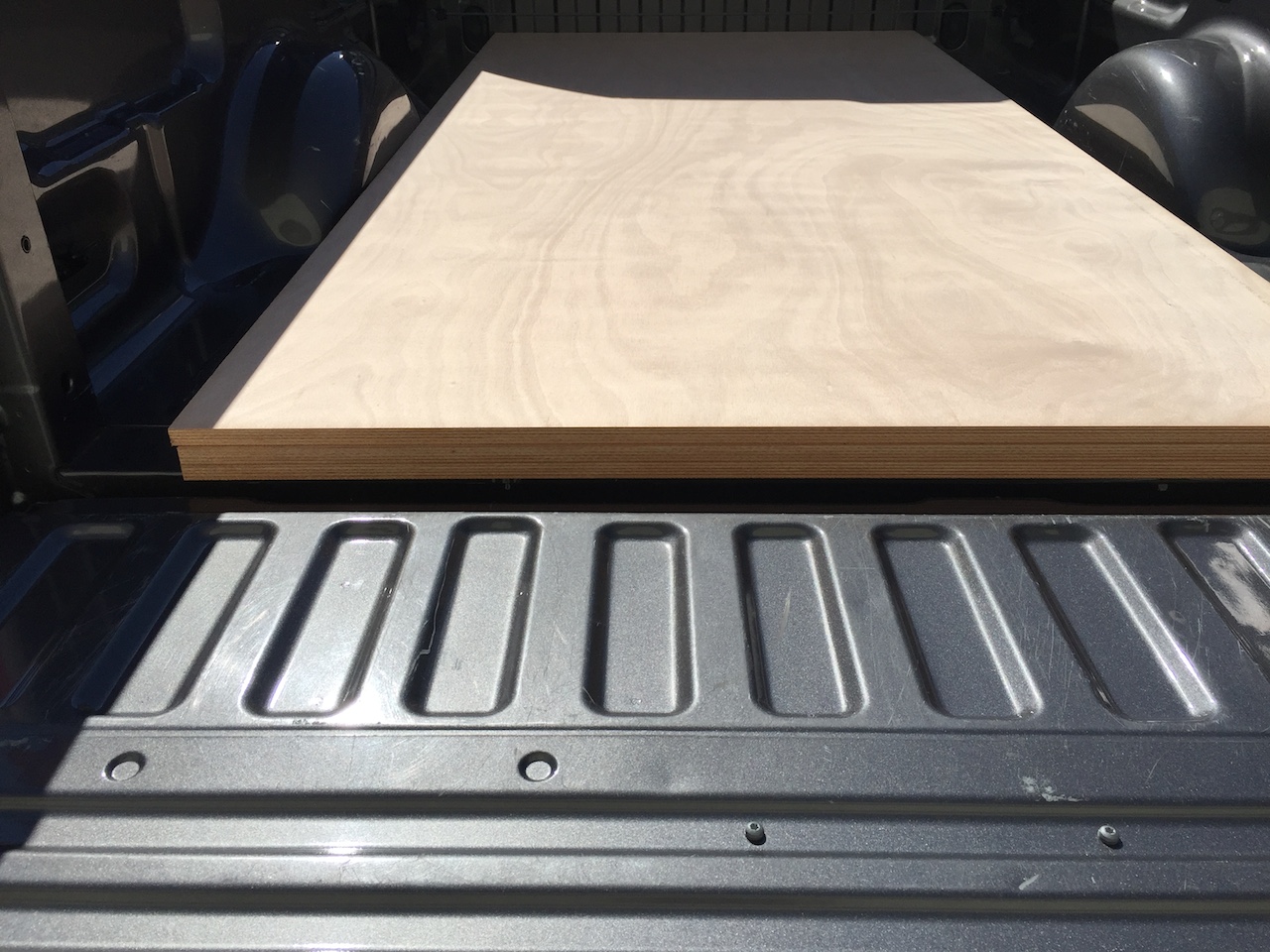
A trip to J. Gibson McIlvain’s Connecticut lumber yard yielded three sheets of 18-mm (3/4-inch) Okume marine plywood.
The main bulkheads (those that separate the head area and the main cabin) were installed in June 2014 (see page dates 6/2/14). The next bulkheads to be installed are two that separate the head area and the forward cabin. The original bulkheads were used as templates for the new.
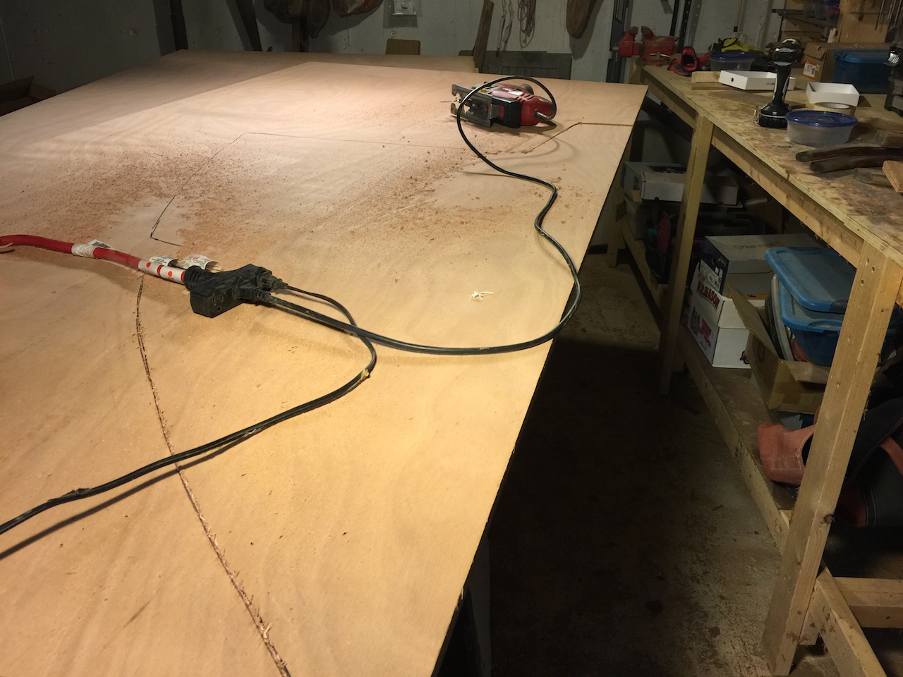
Fitting and aligning the bulkheads is a laborious process that includes perhaps 20 iterations of “check the fit, mark off where material needs to removed, and take off material with a hand plane.” Eventually a good fit was realized for both the starboard and port bulkheads, but recall that the new bulkhead on the port side must be extended amidships, so a rabbet was cut into the inboard edge to accommodate widening the bulkhead later. (More on that later.)
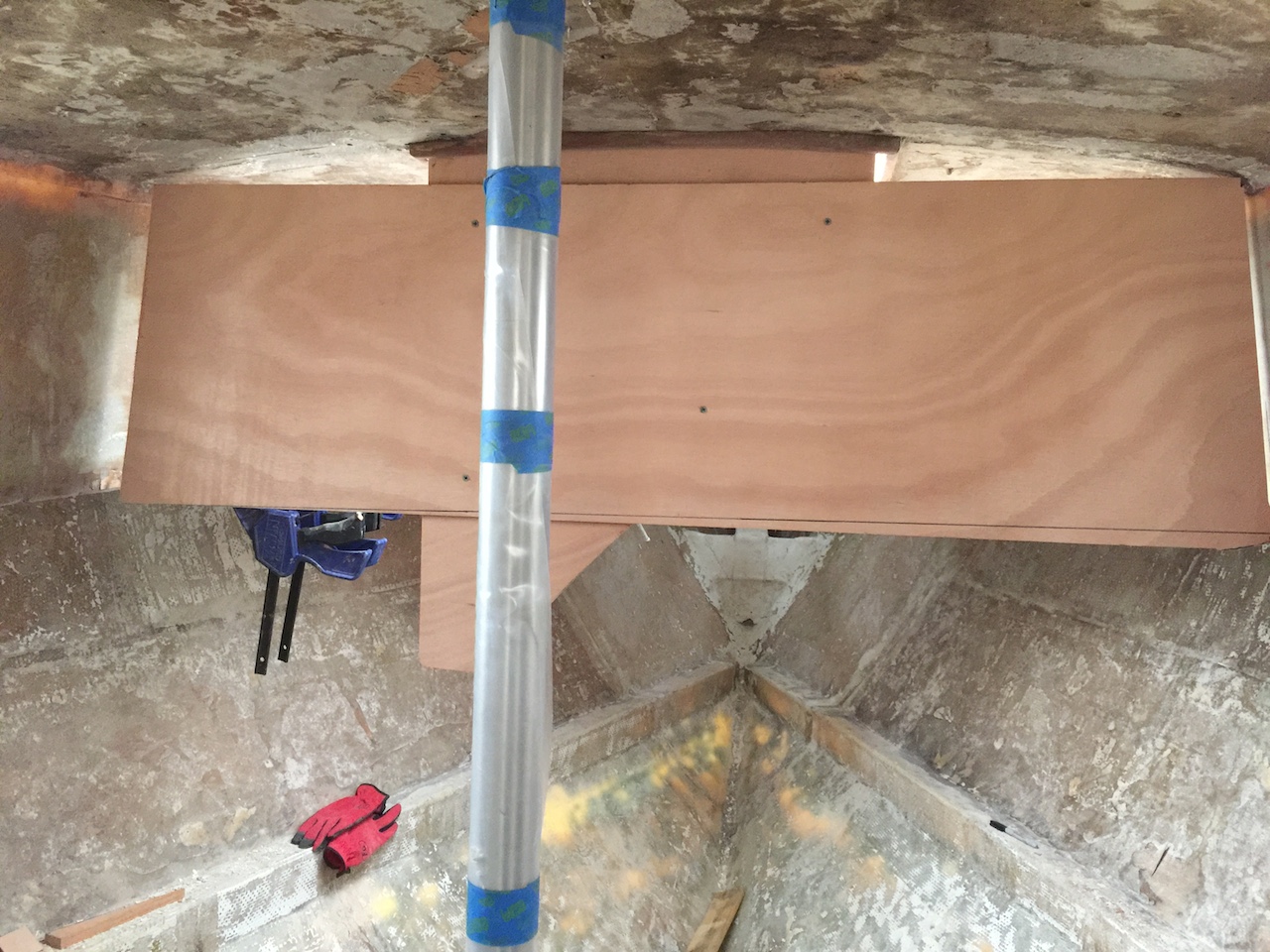
It is crucial to align these bulkheads in the same plane, not only for aesthetic reasons, but because a door will be installed between them. Luckily, one of the inner, vertical surfaces of the forward hatch is just about an inch forward of the desired plane. The image below shows the clamping to the hatch of a piece of plywood that extends vertically down into the cabin. A level was used to confirm verticality.
Next, a wide piece of plywood was screwed to the vertical piece, as shown in the image below. This aft side of this piece defines the plane in which the two bulkheads were installed.
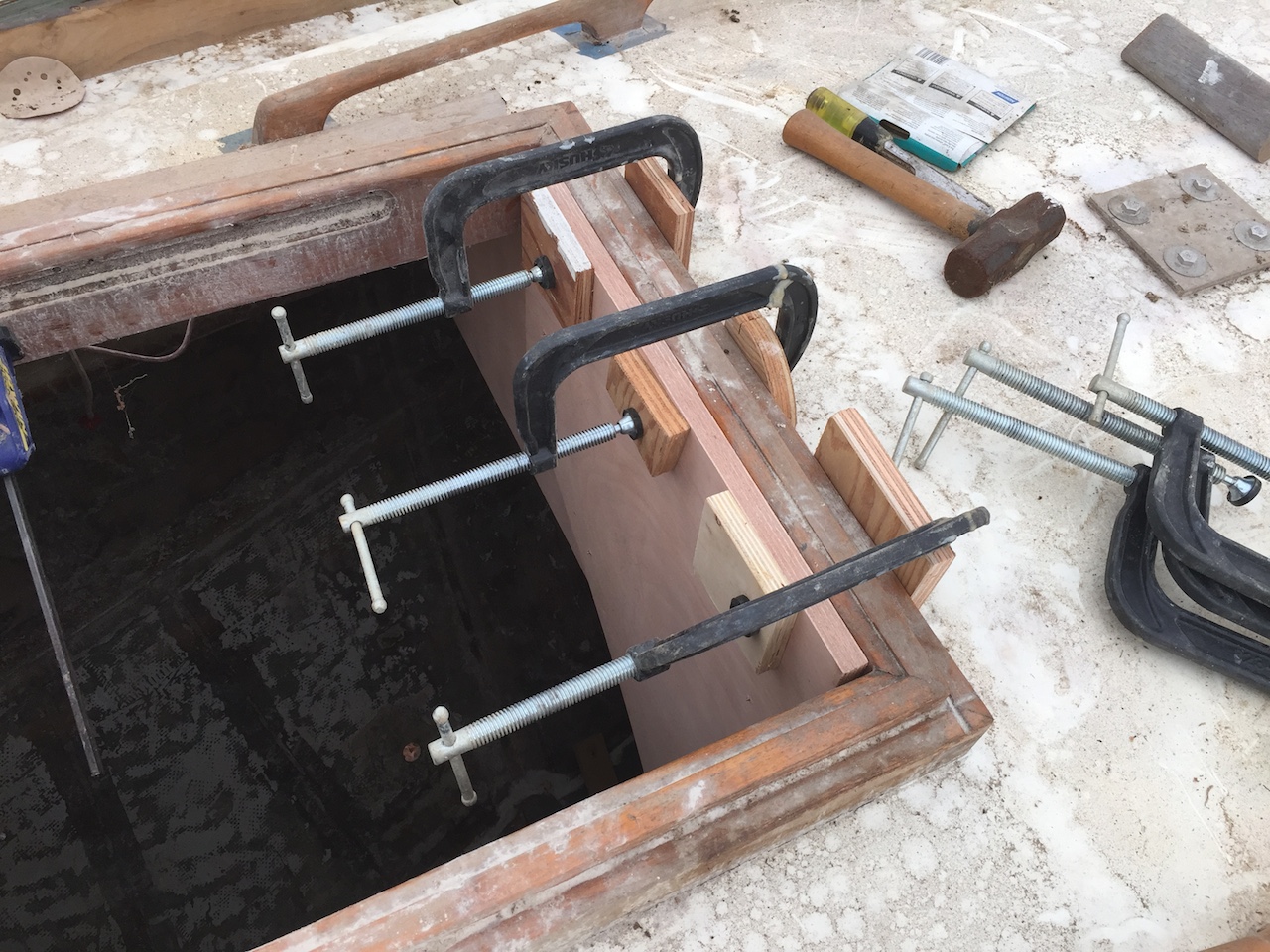
The next photo shows the starboard bulkhead screwed to the “plane” piece and blocked into place with scraps of wood that were hot-glued to the hull.
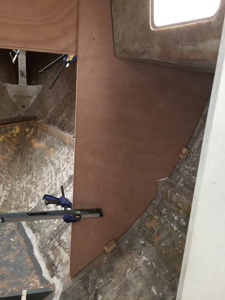
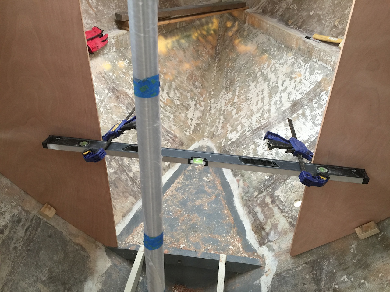
Using a level as a straight-edge and clamping it horizontally, as shown, assures that the lower ends of the bulkheads are aligned properly. Next, the bulkheads were tabbed into place with small (3″ x 8″) pieces of biaxial cloth, and the clamps and other support structures were removed the next day, when the epoxy had cured.
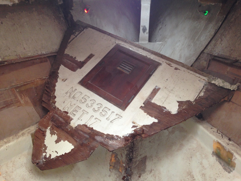
A cold, rainy day prevented continuing work on the tabbing of these bulkheads, so work began on the forepeak bulkhead. The following (old) photo shows this bulkhead coming out, and it was too big to fit through the companionway, so the bottom end was cut off. Obviously, then, the new bulkhead must be built in two pieces to be assembled in the boat.
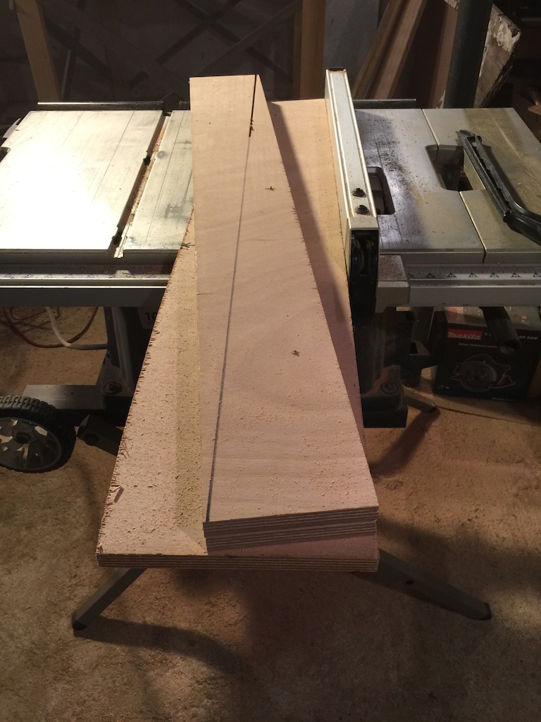
The two pieces will be joined with a scarf joint, so a 12-1 scarf jig was fabricated out of scrap plywood. First, two pieces of plywood that make a 12-1 slope were created using the table saw. These pieces must be identical, so they were made by screwing two equal-width pieces together and cutting simultaneously.
Next, he two side rails were connected with smaller blocks of plywood and screws.
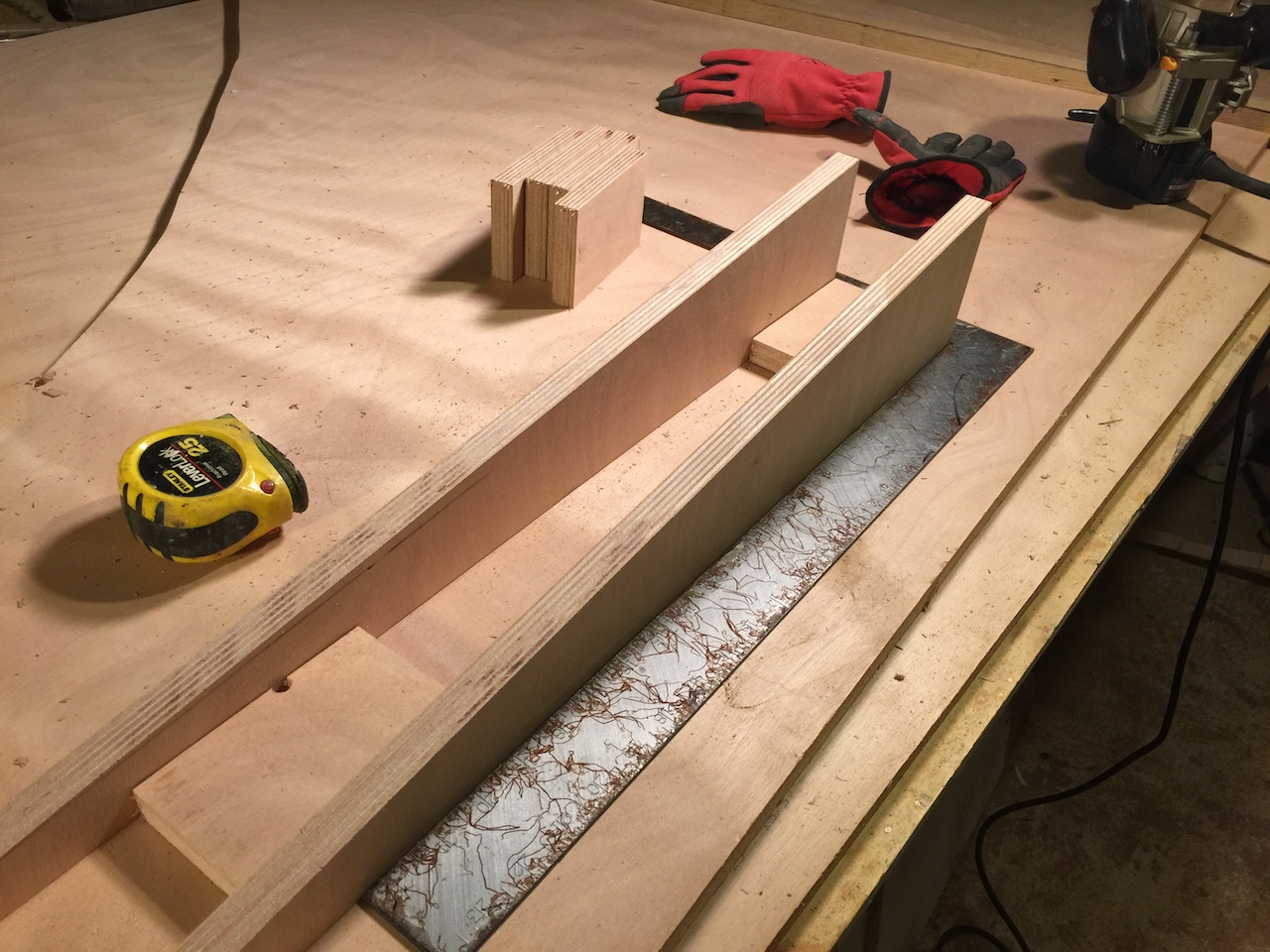
Plywood tabs on the sides and back provide a means to clamp or screw the jig into place. A router with a straight bit slides along the rails and cuts a 12-1 scarf into the plywood.
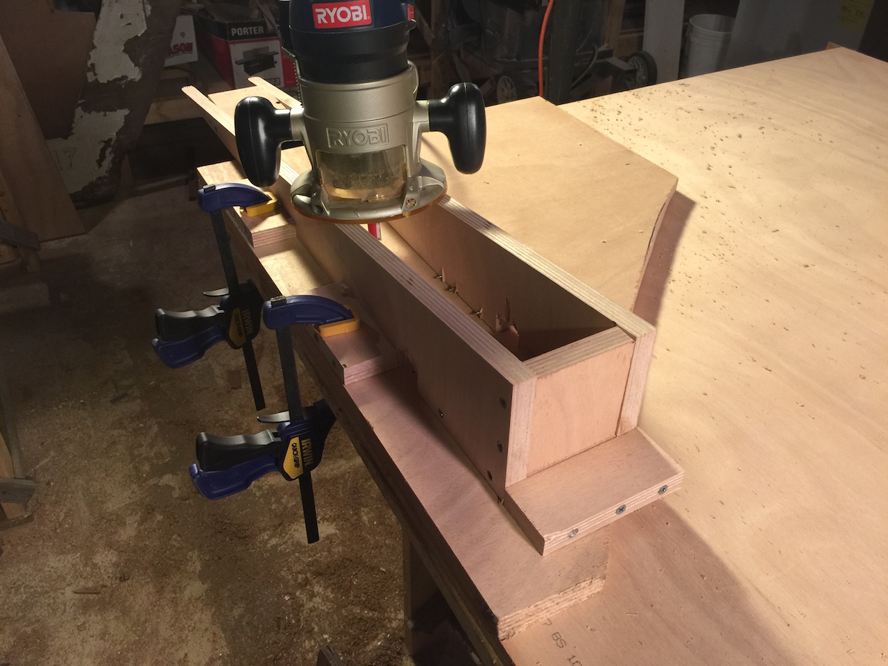
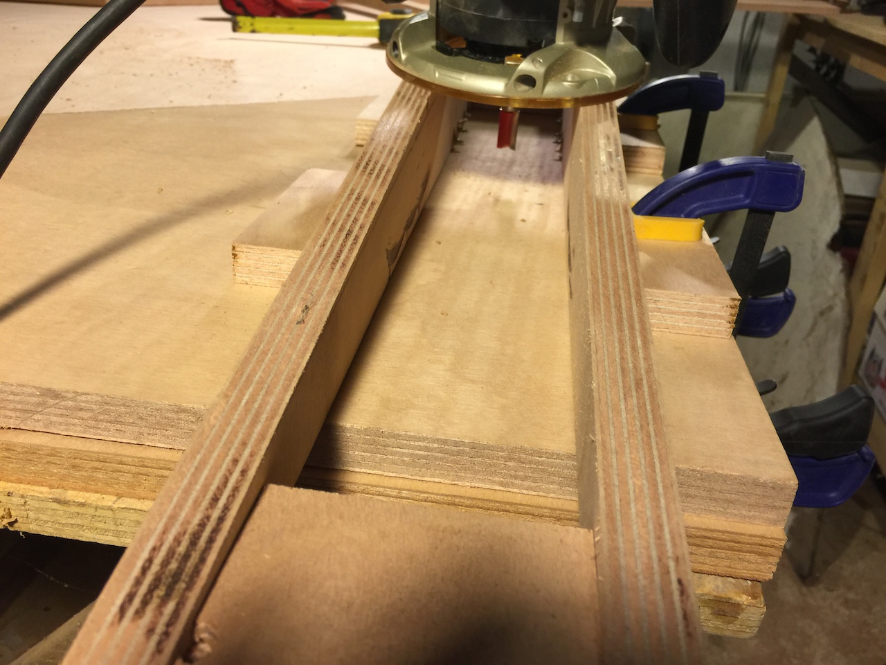
After the material between the rails is routed out, the jig is moved, carefully aligned, clamped/screwed, and then the routing begins again. The following photo shows the situation after several iterations.
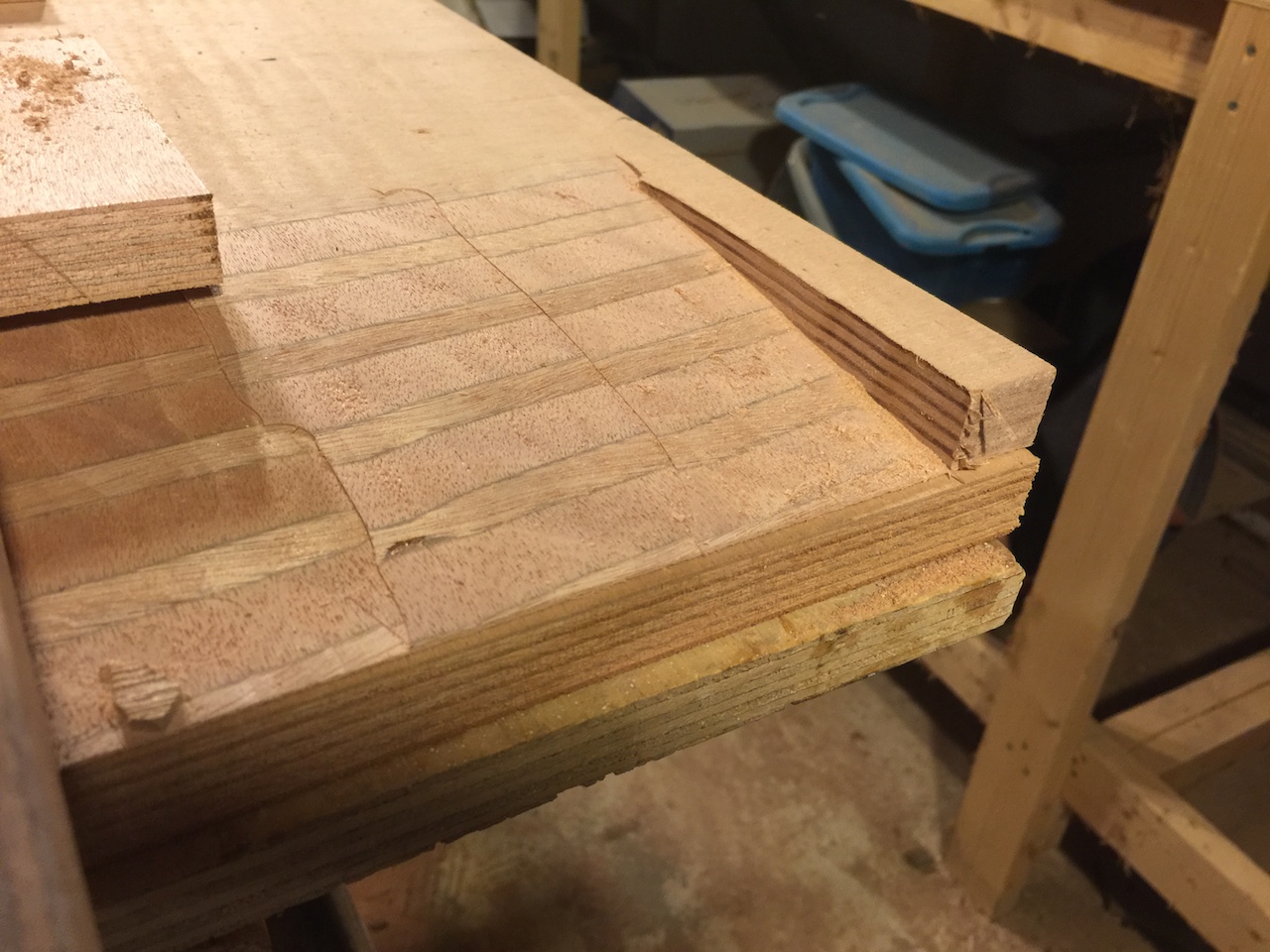
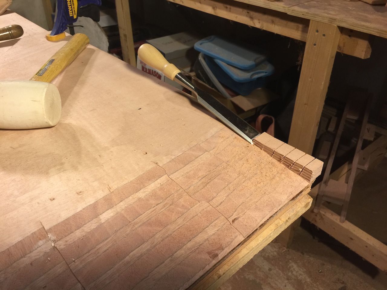
The extra material on the ends were removed by cutting kerfs with a dovetail saw and using a sharp chisel to remove the bits.
Finishing off the job with the belt sander yields a smooth joint that tapes down to a feather edge.
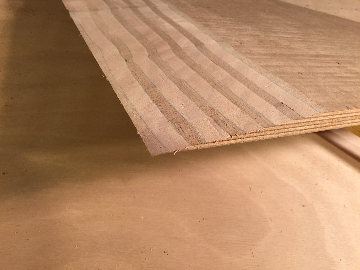
The piece in the photo above will be cut out as the small piece, and will be joined to the larger piece once the two pieces are on board. The next steps are to cut out the lager piece of the forepeak bulkhead and then cut the scarf in that piece.