6/19/16: Icebox, Shelves, Seats, Aft-compartment Bulkhead
ICEBOX
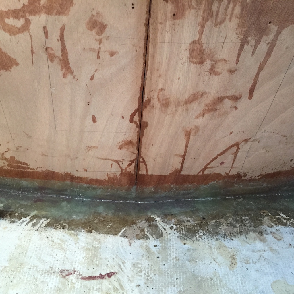
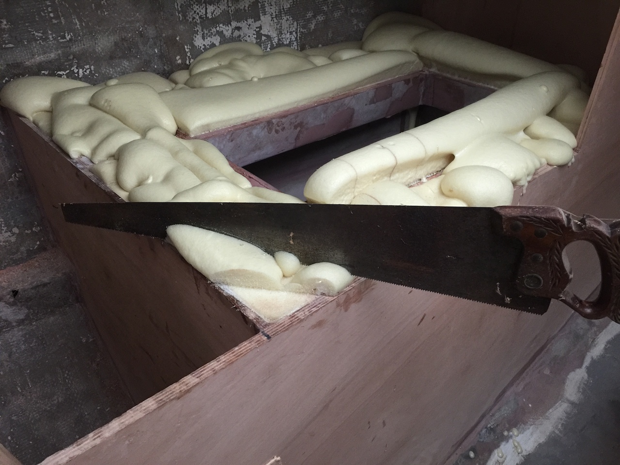
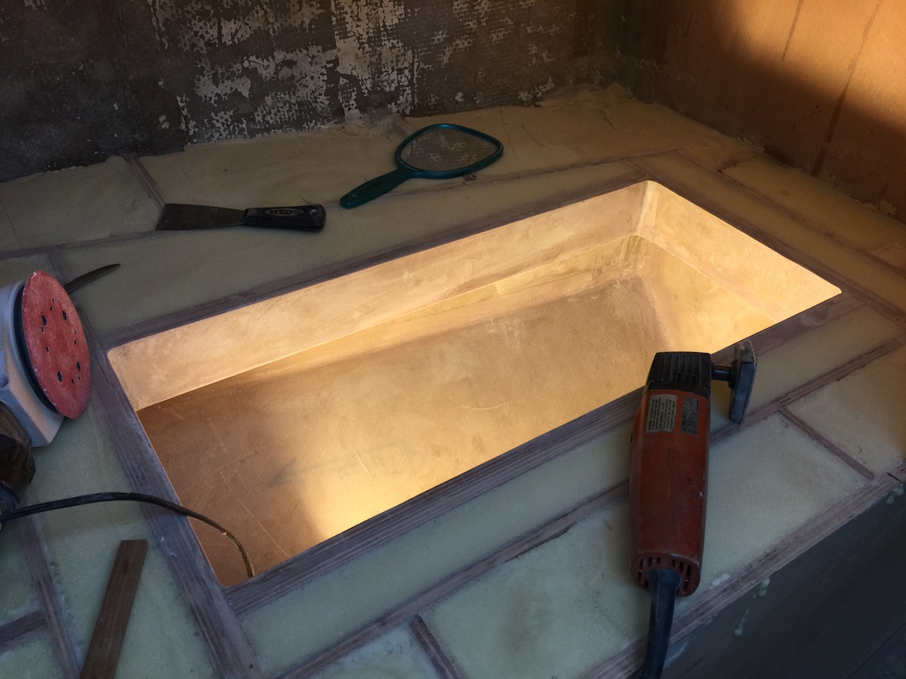
When the insulating foam cures, it becomes a hard, cuttable, sandable substance. I started by cutting off the high spots, then used the disk and belt sanders to bring it down to level with the frame. A chisel and knife were useful in cleaning up the corners.
Next, I ran a fillet of thickened epoxy along the seam where the roof meets the walls. The following diagram shows, schematically, a cross section of the icebox as if one were looking fore/aft. It does not show the support frame.
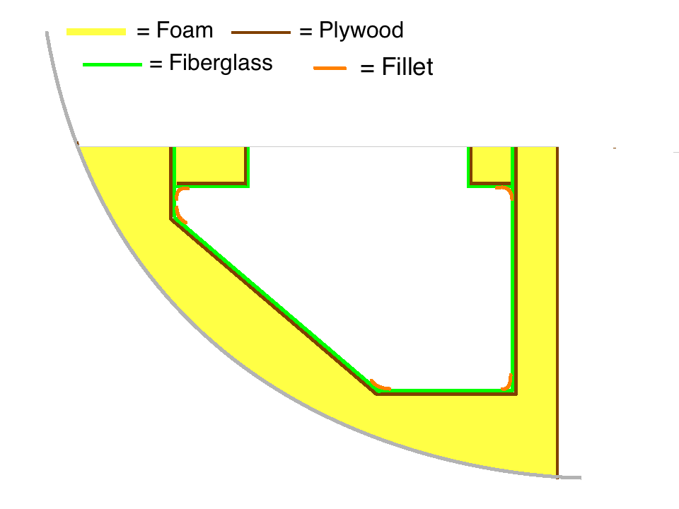
Making and sanding the fillet that joins the “roof” to the sides was difficult because I could not see it except by sticking my head into the box or using a hand-held mirror.
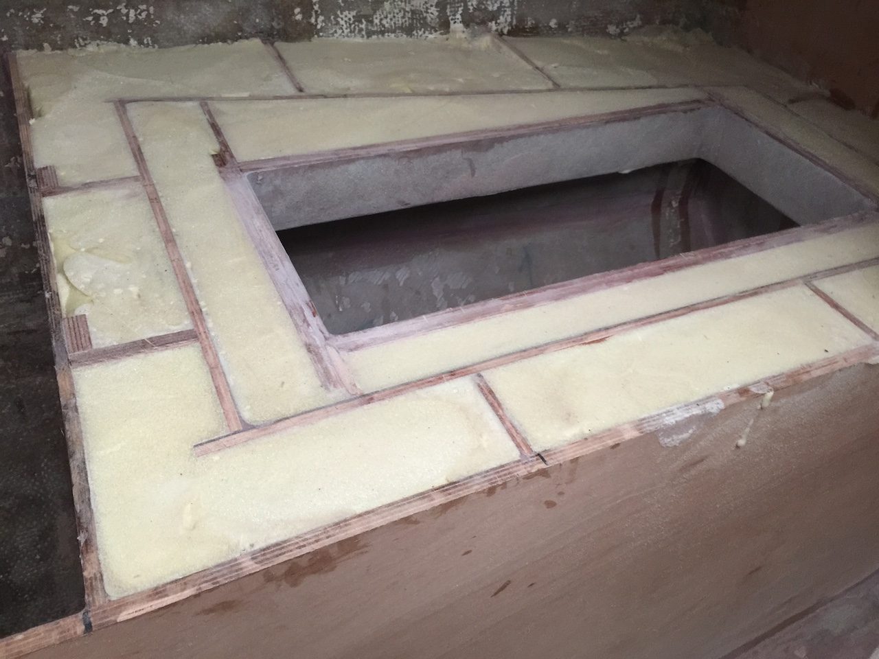
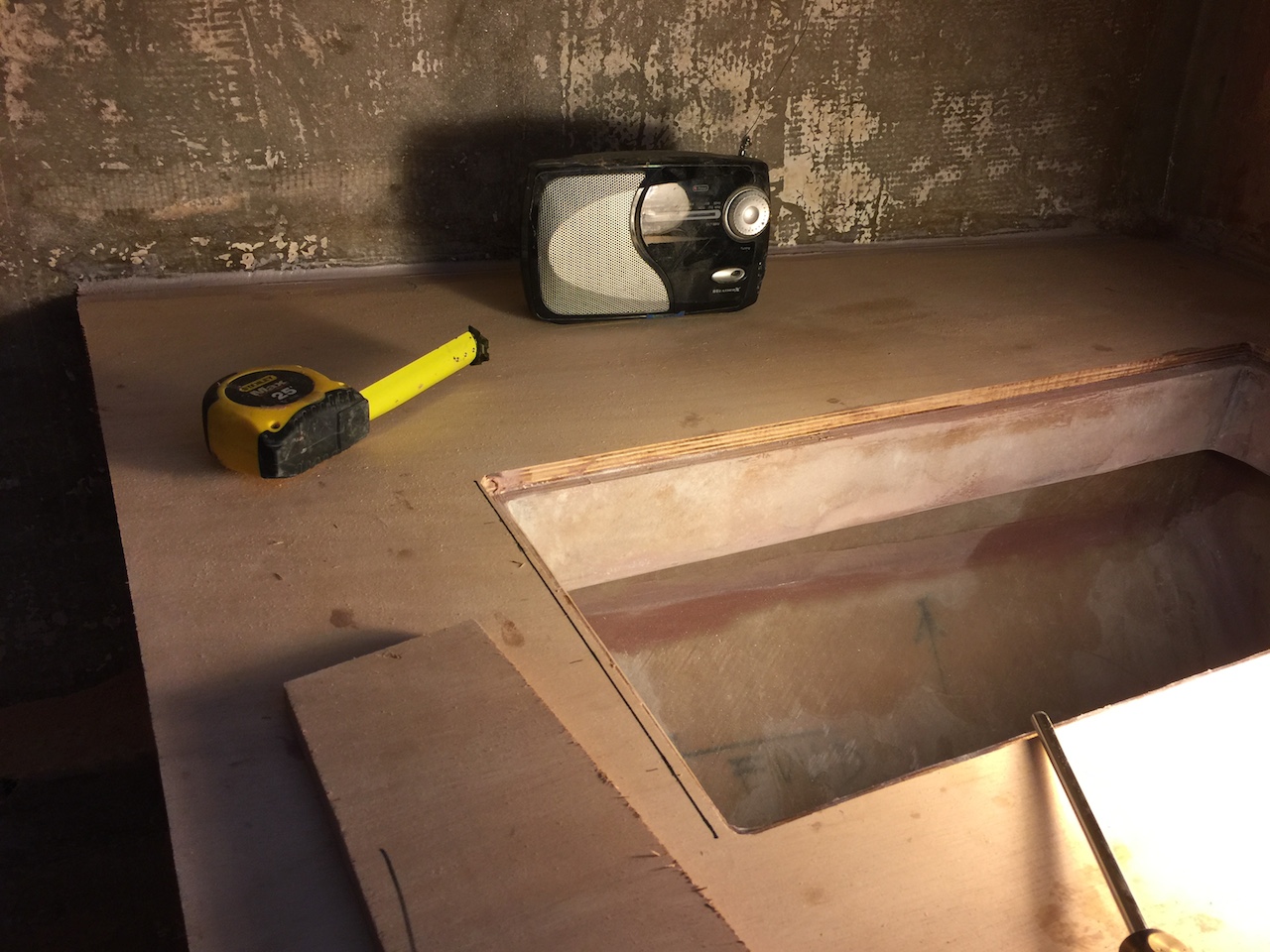
Next, I tested the fit of the countertop and then cut a rough, undersized opening for the lid.
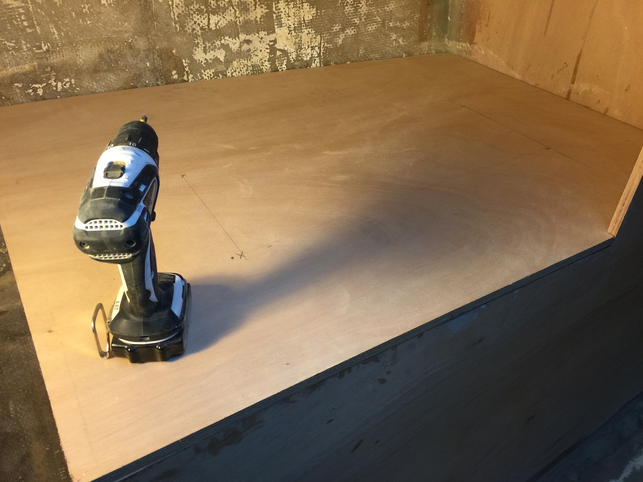
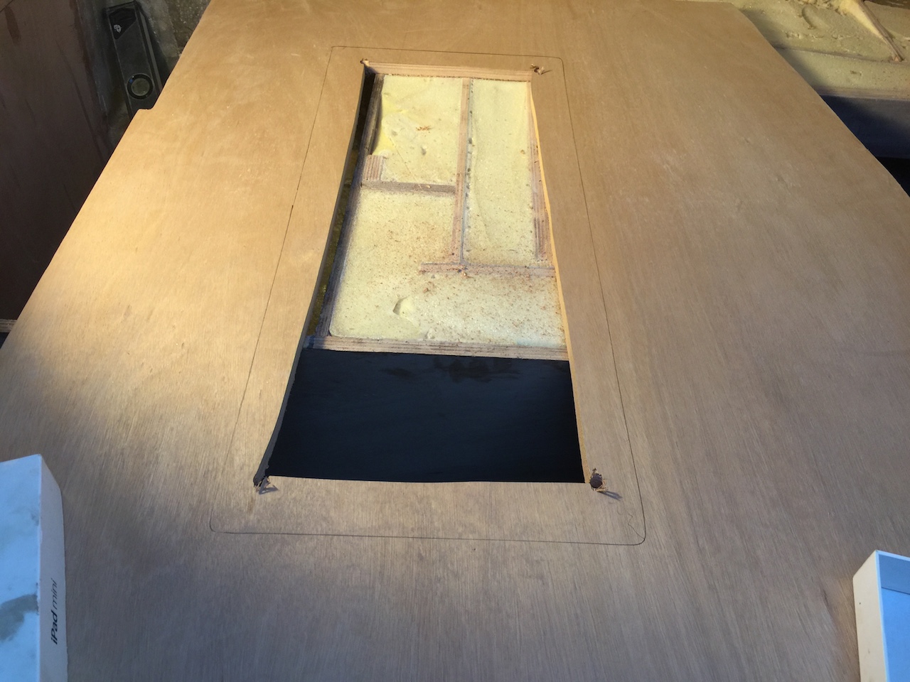
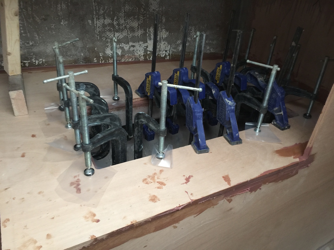
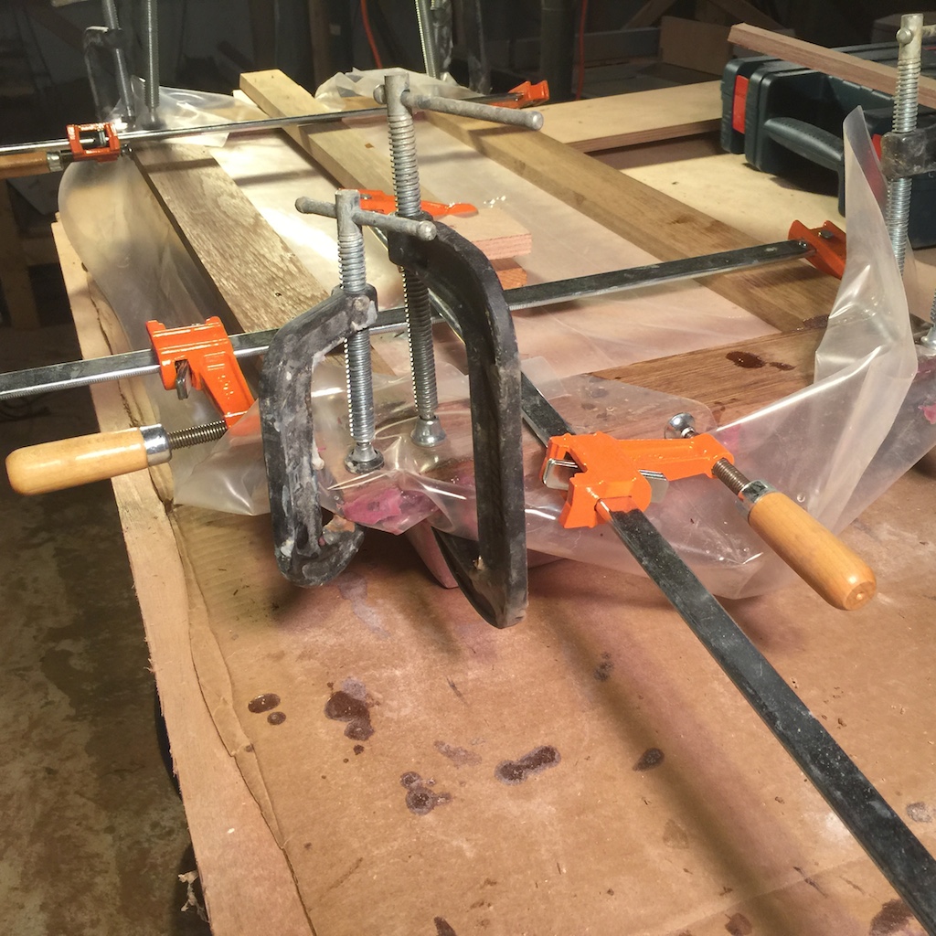
After tracing the lid opening from inside the box, I cut the hole to closer to its final dimensions, then routed it smooth, then epoxied and clamped it all down.
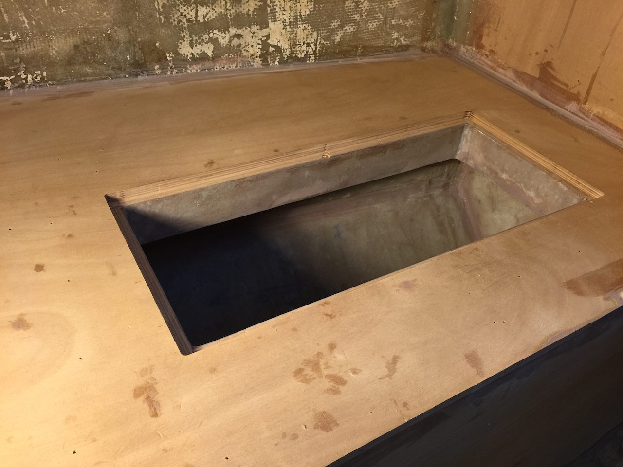
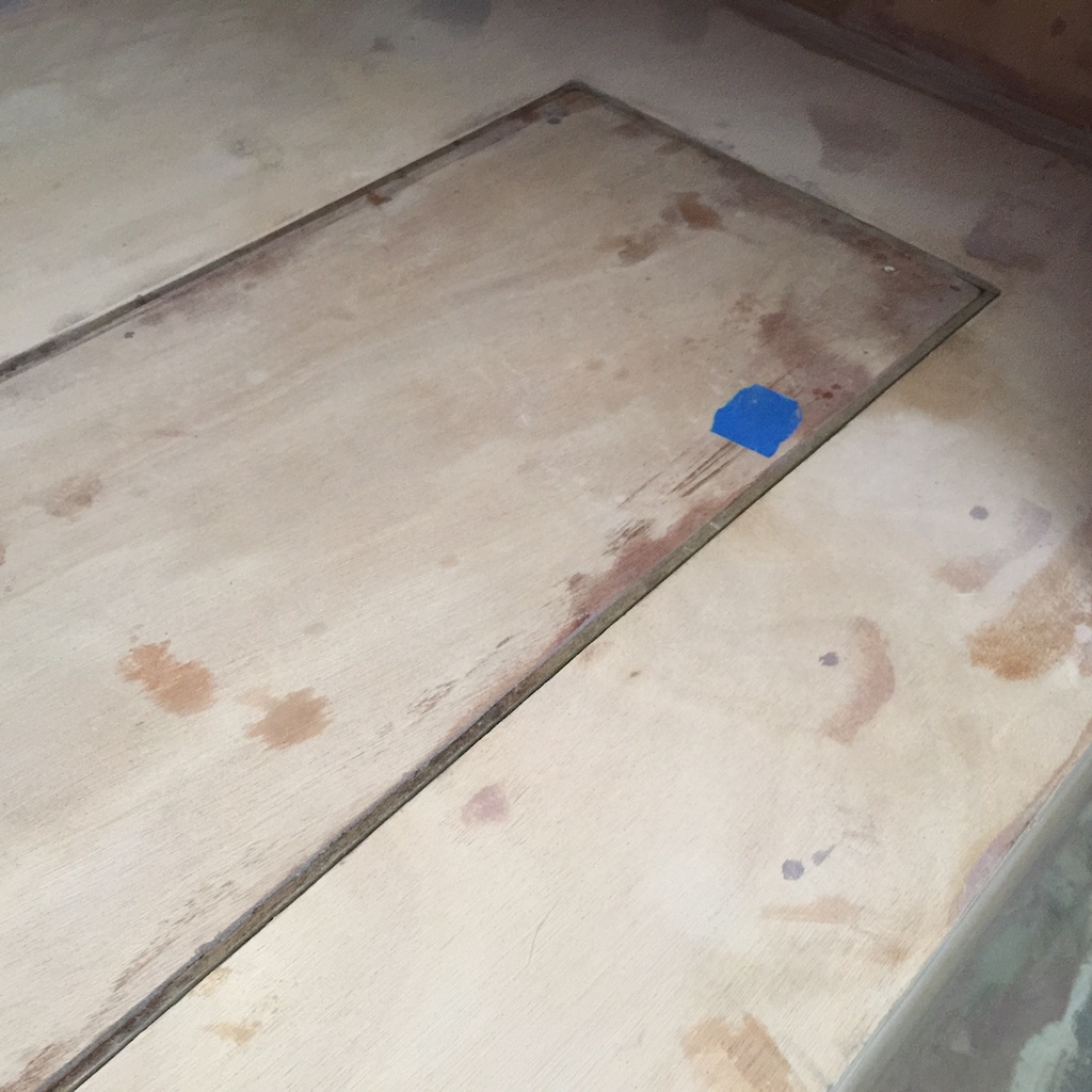
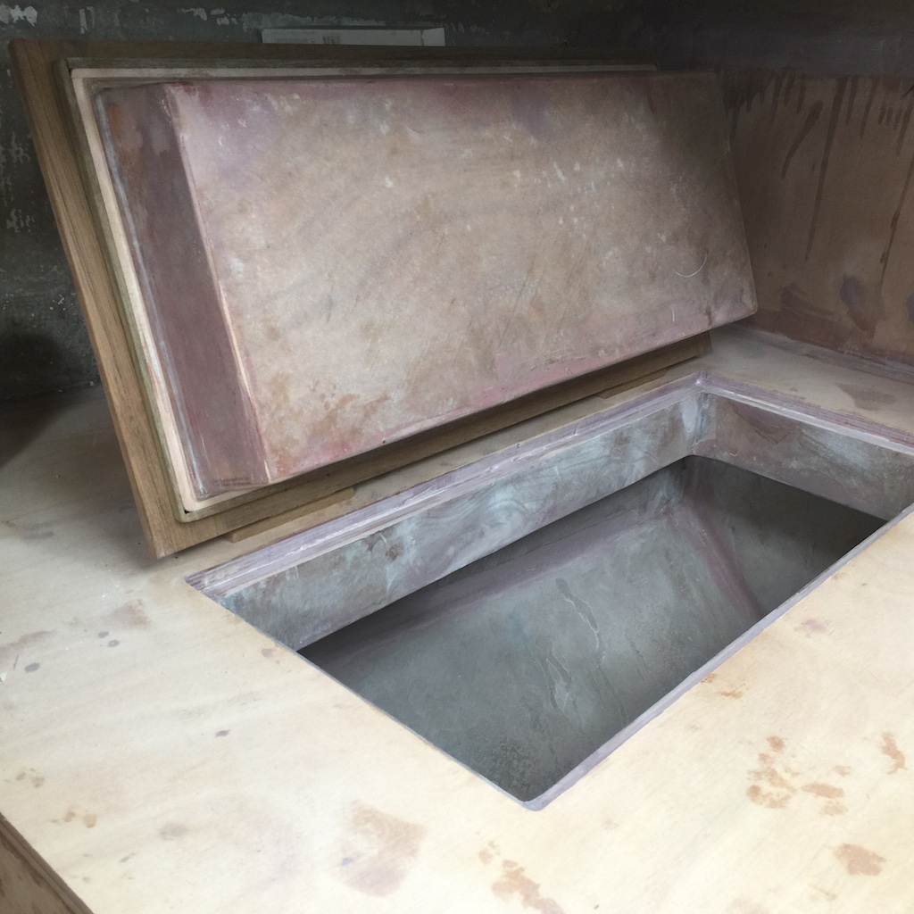
Finally I have permanent shelf space for tools and other equipment. (Note the fillet of thickened epoxy along the perimeter of the countertop. Eventually I will run a 2-inch layer of fiberglass around the edges that meet the hull or a vertical bulkhead.)
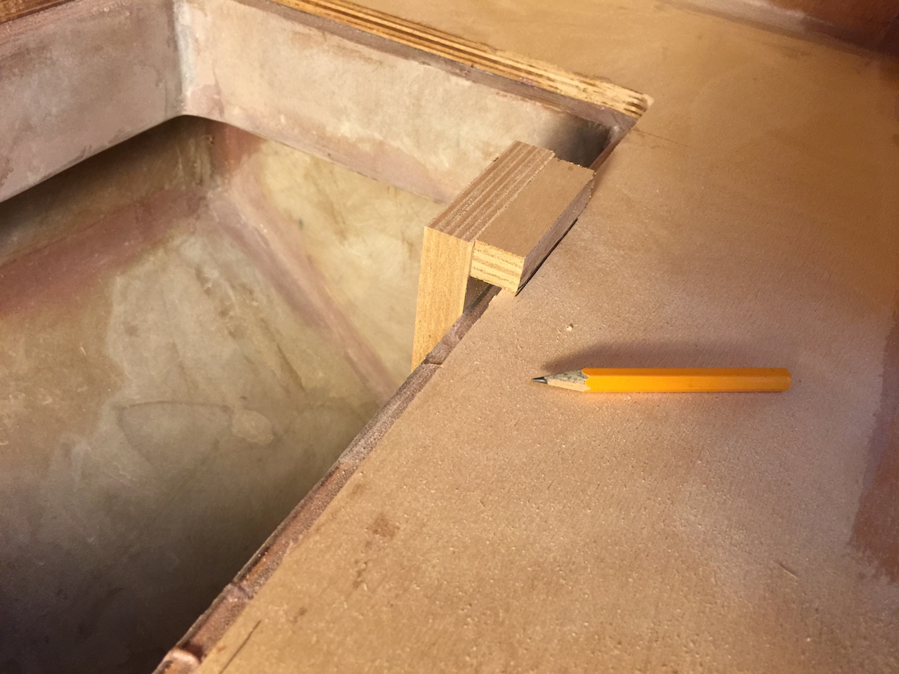
I decided on a 3/4-inch rabbet around the top, so I built a simple jig to mark up the countertop, then routed to the new dimensions.
I added a teak “edge band” around the lid edge as a means to match the size of the rabbet permimeter.
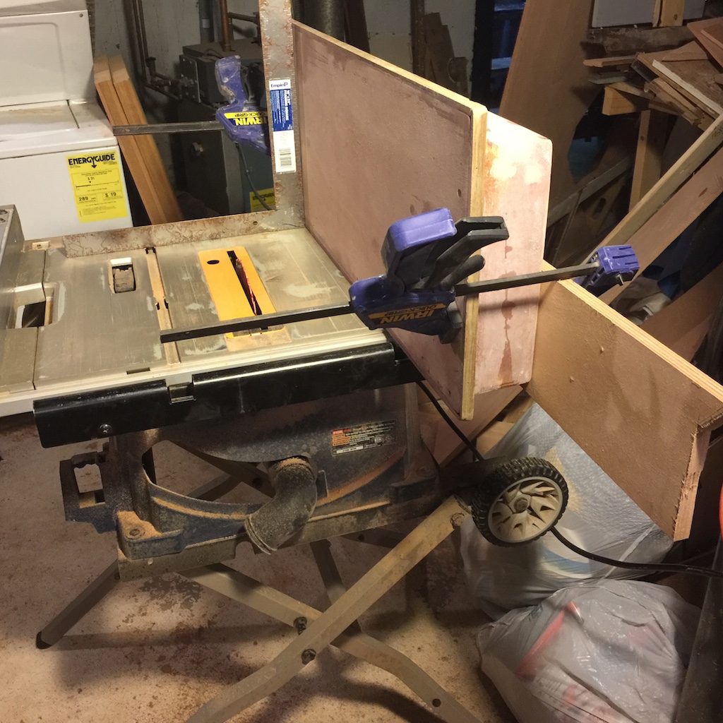
A molding piece will sit flush on the countertop, and I needed to narrow the lip on the lid so that it doesn’t rest on the rabbet in the countertop. The following photo shows how I used the table saw to cut away the bottom part of the lip.
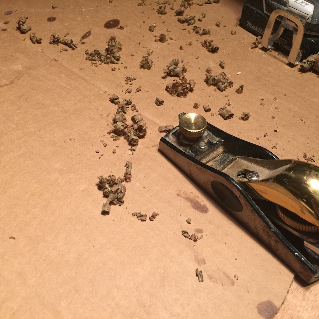
The block plane was useful for fine-tuning the top, and shavings are always preferable to dust.
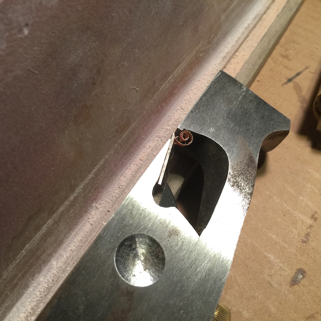
The following photo shows the lip and the rabbet plane being used to make final adjustments.
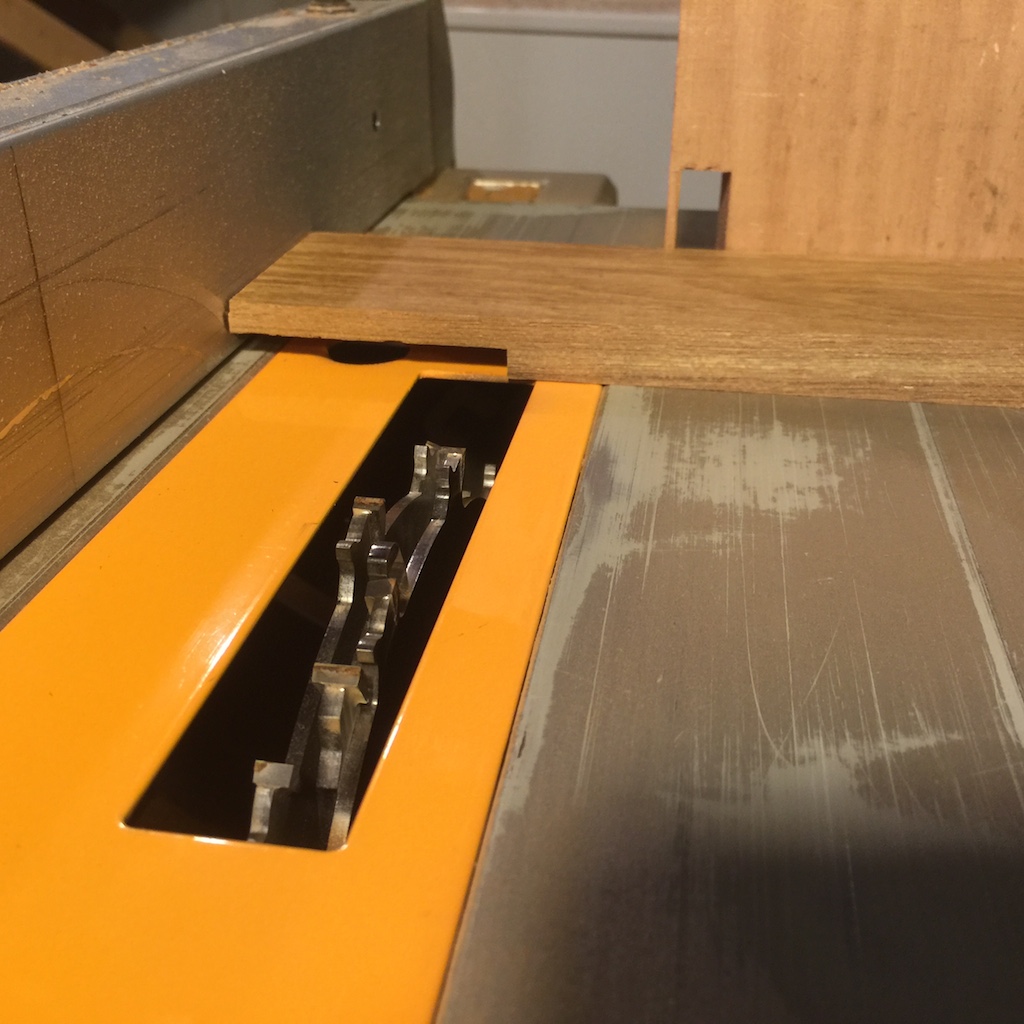
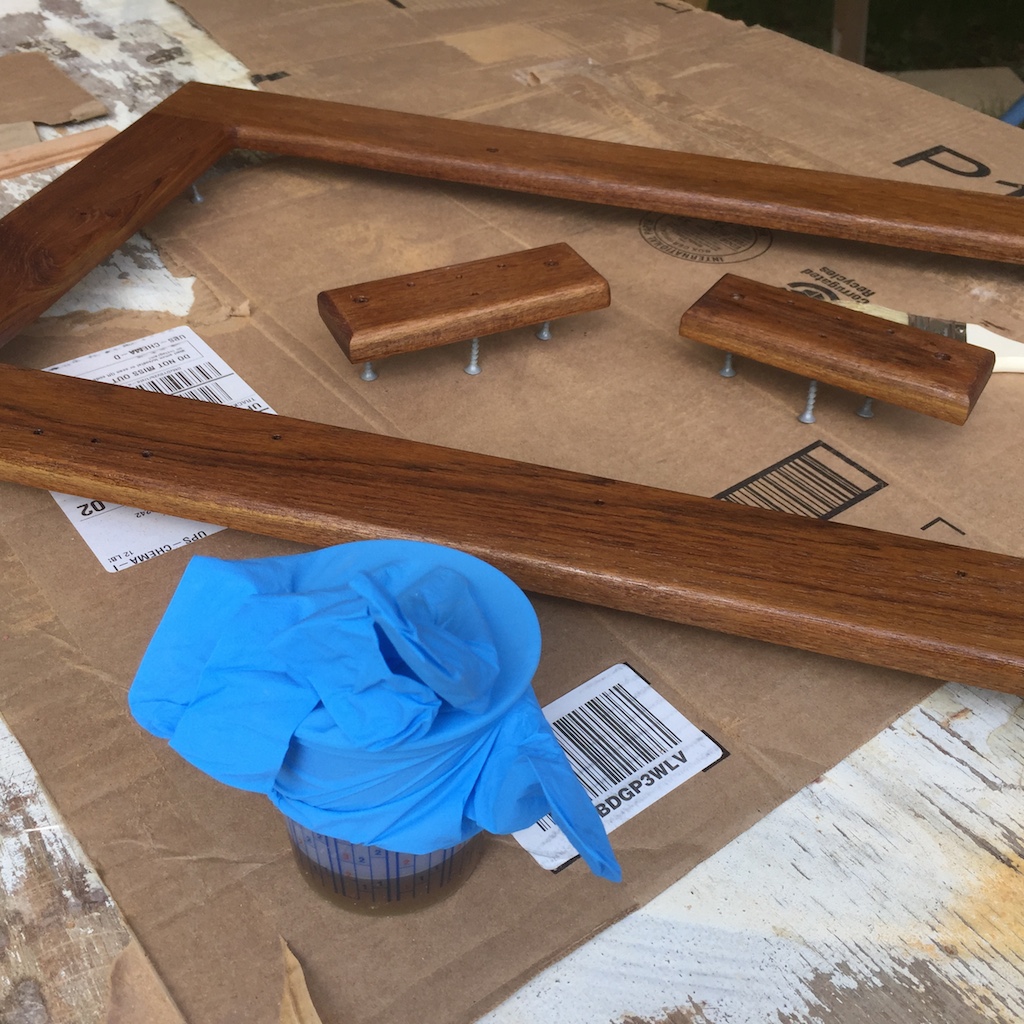
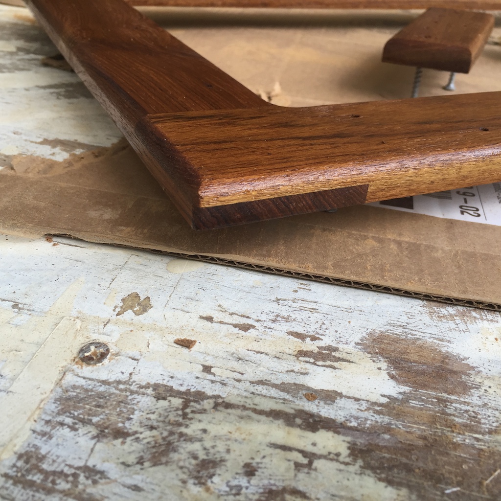
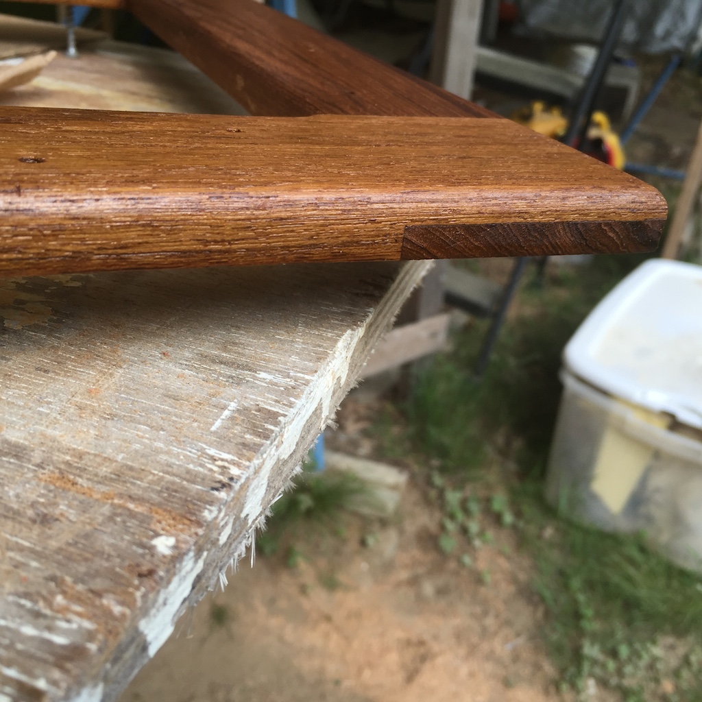
I used 1/2-inch thick teak for the molding that will run around the perimeter of the lid. The four pieces were joined using half-lap joints, glued up with epoxy. The dado set (a set of wide, stackable blades for the table saw) makes easy work of cutting away half of the thickness. Careful measuring, slow cutting, and using the rip fence for a “stop” make pretty nice joints.
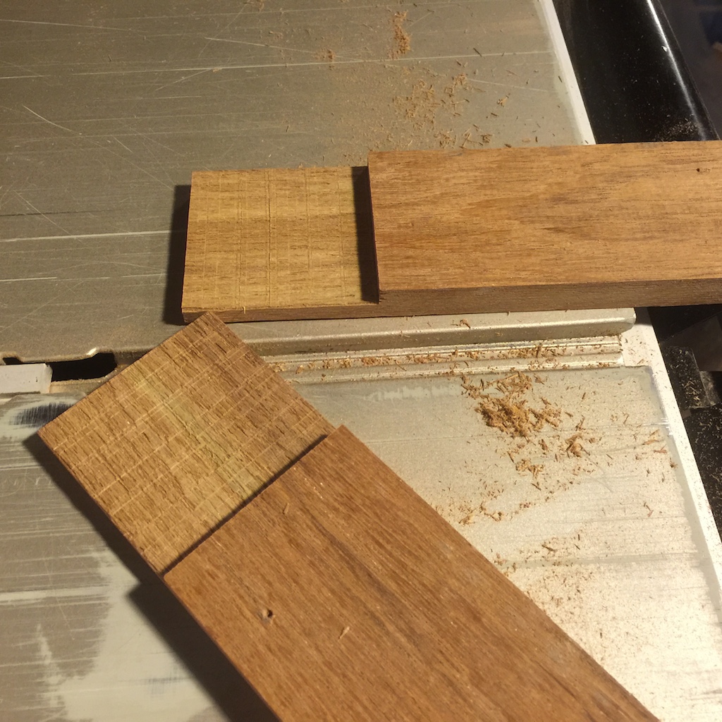
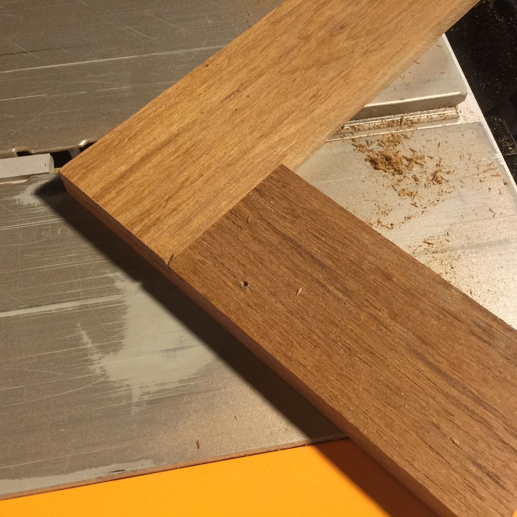
The next two photos show a trial joint using scrap.
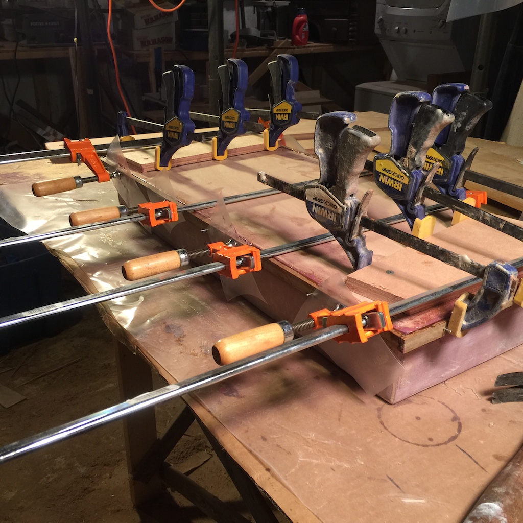
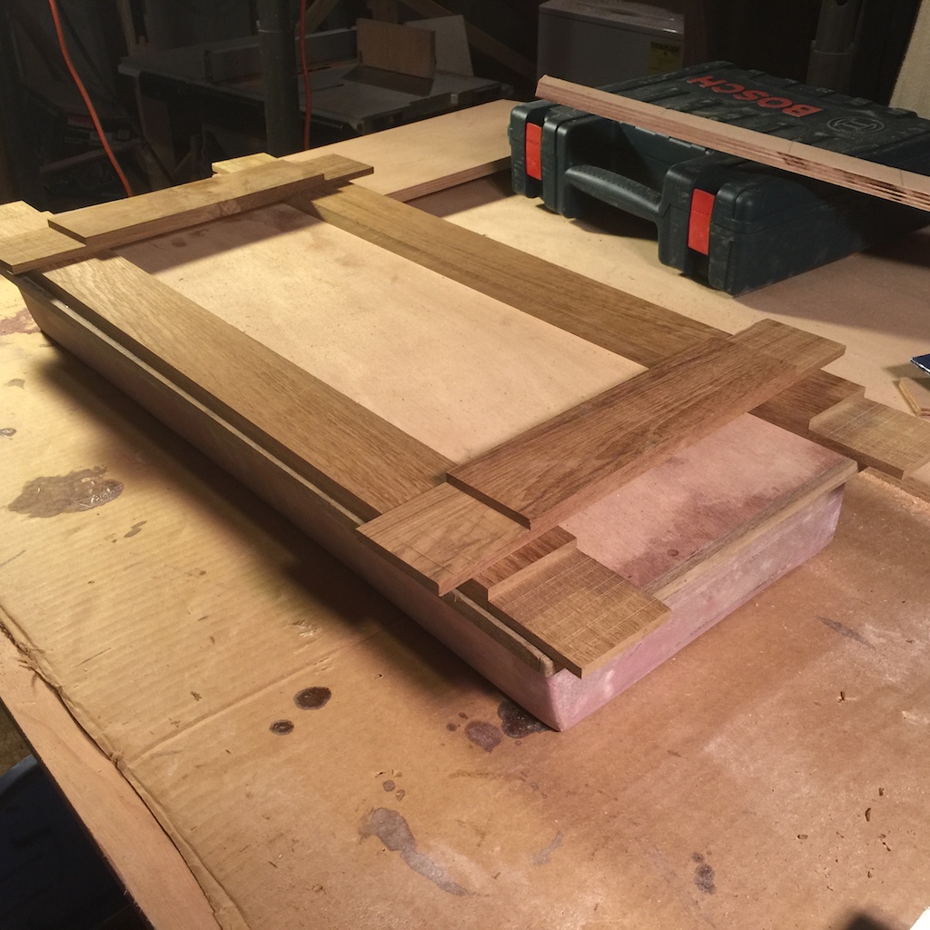
The molding was assembled, test fitted dry, then glued up (“glue up” always means epoxy unless otherwise specified) and clamped. Note that I have not yet glued/screwed the molding to the lid.
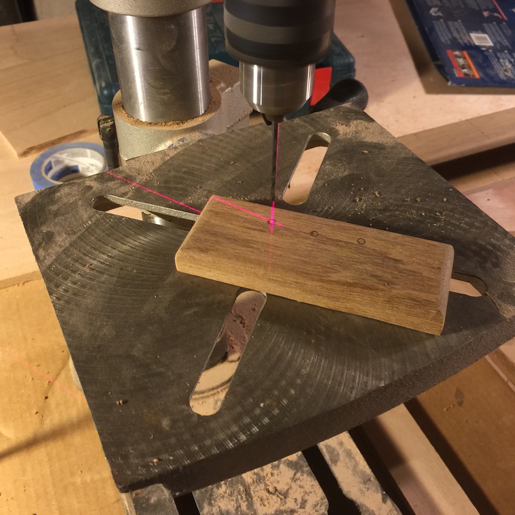
After the epoxy dried, I found that the rectangular molding wasn’t quite square, so I made some final adjustments using the table saw and router. Next, I made the pieces that will go under the off-lid side of each of the two hinges. The drill press was then used to make small pilot holes for temporary screws in both the hinge pieces and the molding.
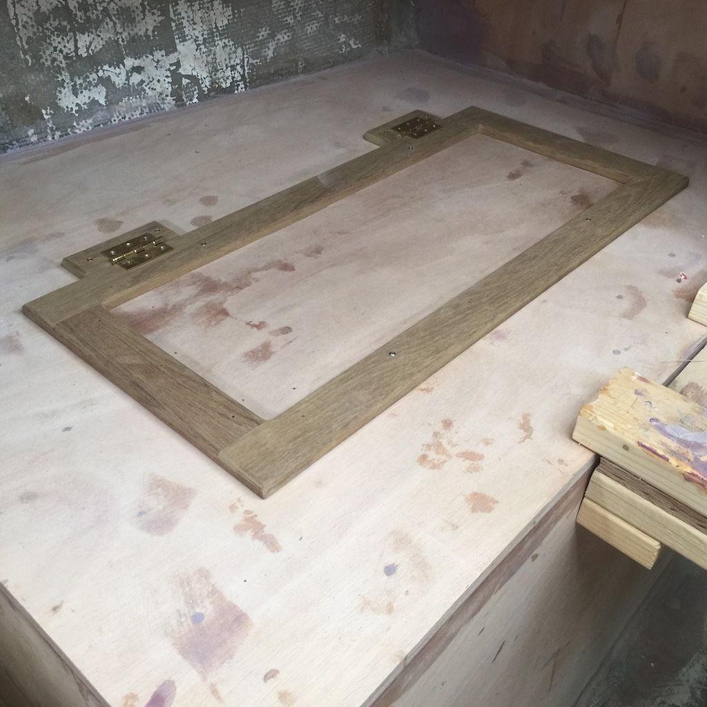
The next two photos show a test fit, using the hinges, but with temporary screws that are smaller than the screws I will use in the final installation.
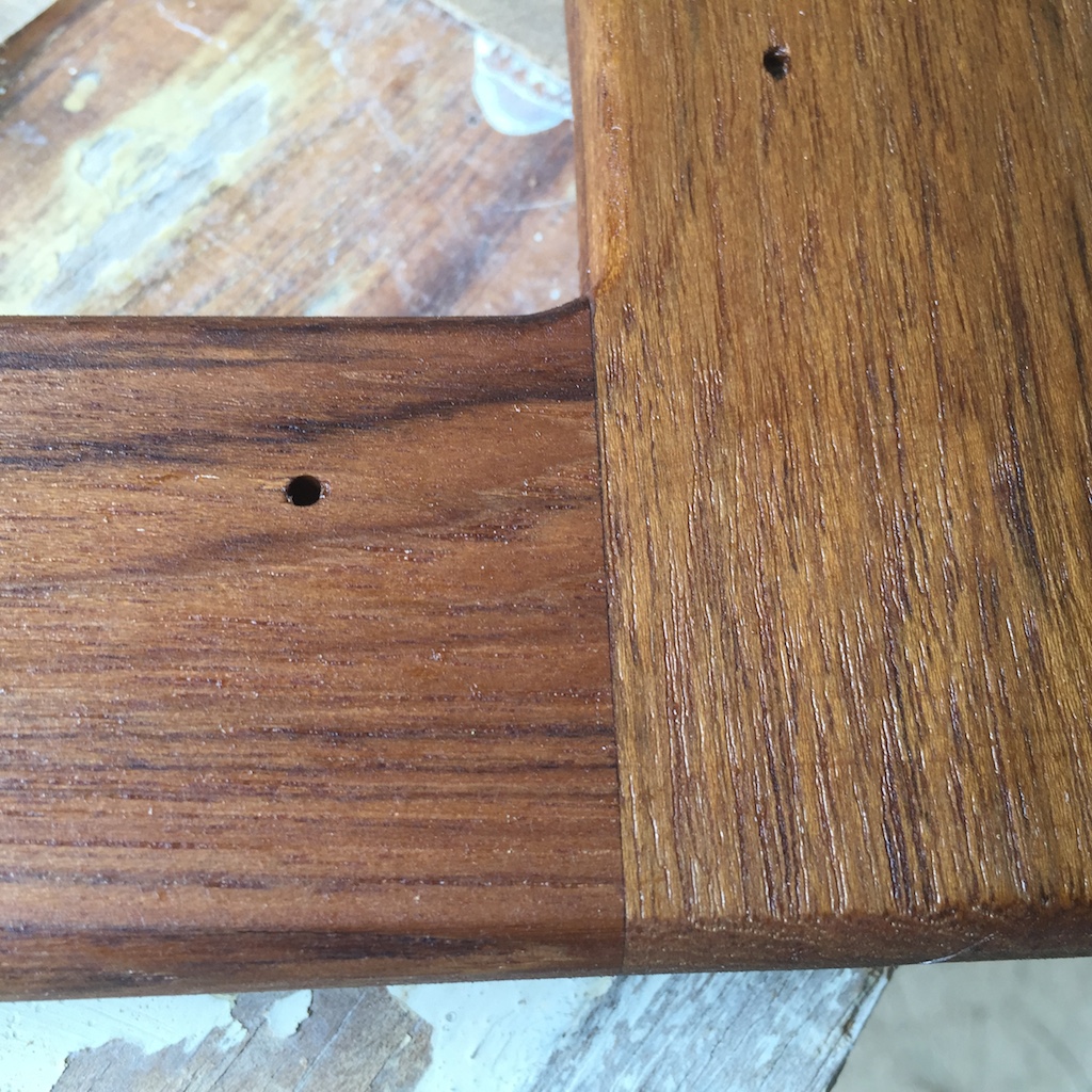
Next, I disassembled everything and applied two coats of thinned varnish to the molding. The following four photos show the results, where you can see close-ups of the lap joints.
SHELVES
I try to have more than one project going at once as a means to work efficiently. With that in mind, I began construction of the settees by installing the primary shelves on the port and starboard sides.
The following photo is from 2007, and shows the starboard-side shelving units that I partially restored, and have now long been completely removed.
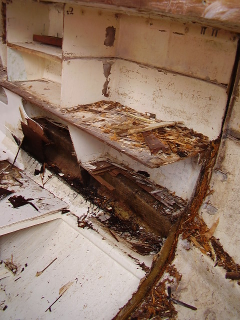
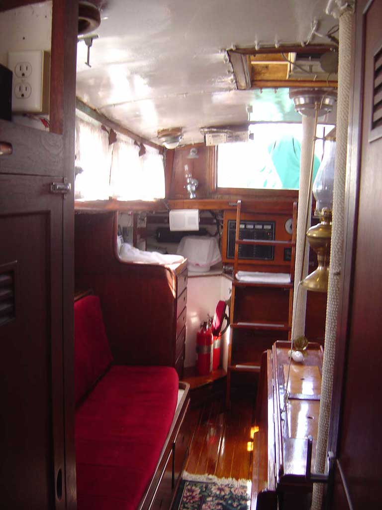
Besides their poor condition, there was another problem with the original shelves. The settee backrests begin where the shelves terminate on the inboard edge. The shelves extended pretty far inboard, robbing the settee seats of width. The following (very old) photo shows starboard-side settee. These original seats were ideal for sitting upright and eating, but not so great for lounging and relaxing. More modern boats often have more “couch like” accommodations.
This problem was even worse in the Hinckley Bermuda 40, in which pilot berths sat outboard of the settee seats, resulting in an even more cramped configuration, as shown in the following photo:
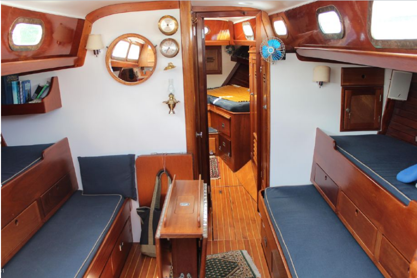
To appreciate how narrow these seats are, note that the backrests are solid wood and imagine what a 4-inch foam pad on those backrests would do. At the time, however, these cabins were considered spacious, but times have changed.
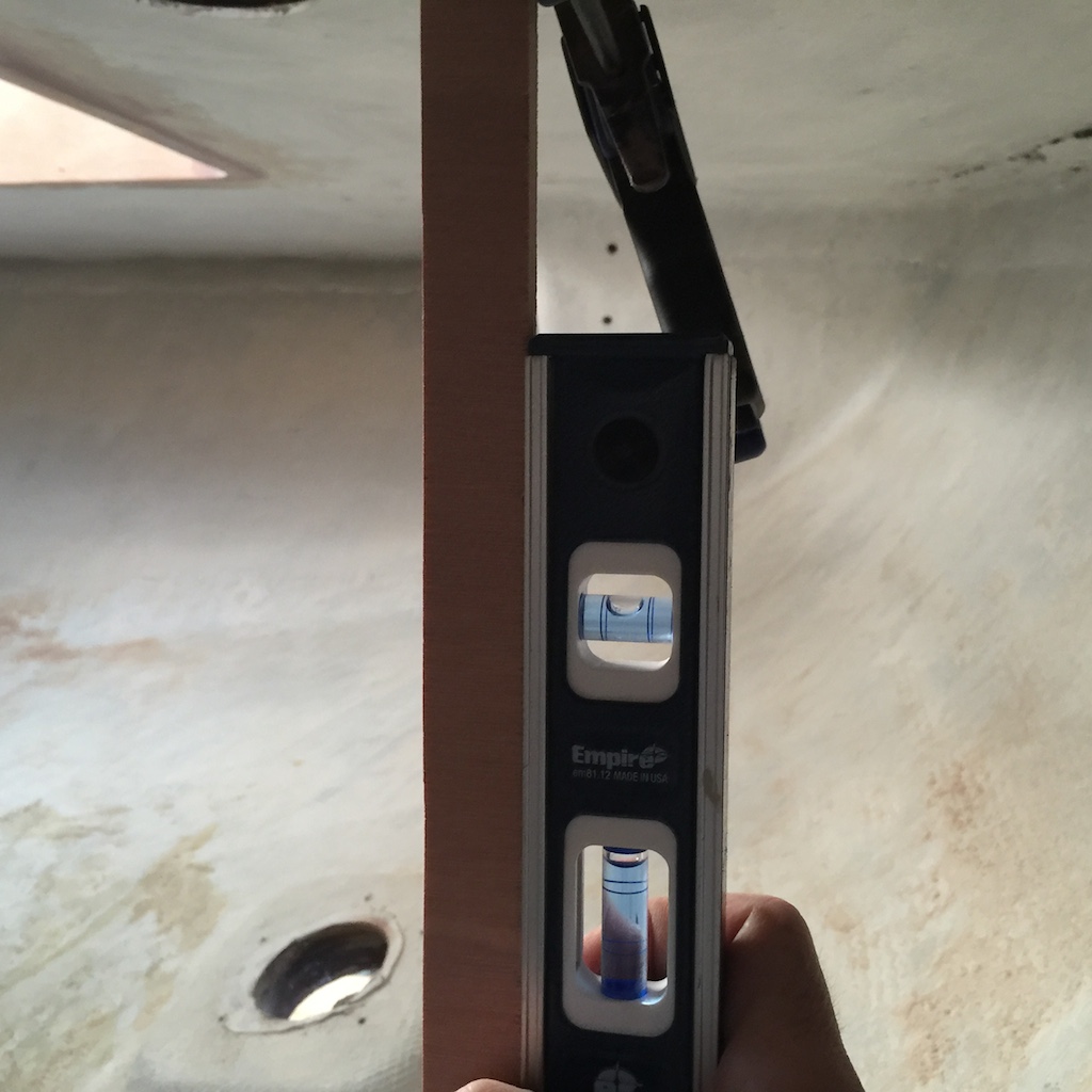
To solve this problem on Thalassa, my plan is to simply make the shelves about 5-6 inches narrower. (The ideal backrest angle is between 15 and 25 degrees, which I think is larger than the angle of the original backrests. I might be able to measure the original angle if I can find some marks on original bulkheads.) I expect that the seats will be at least 5 inches wider than the original, which is a significant increase.
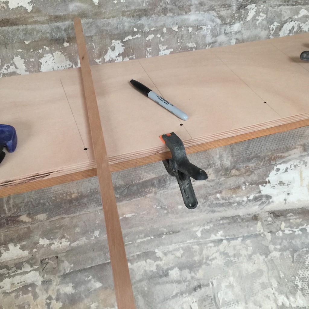
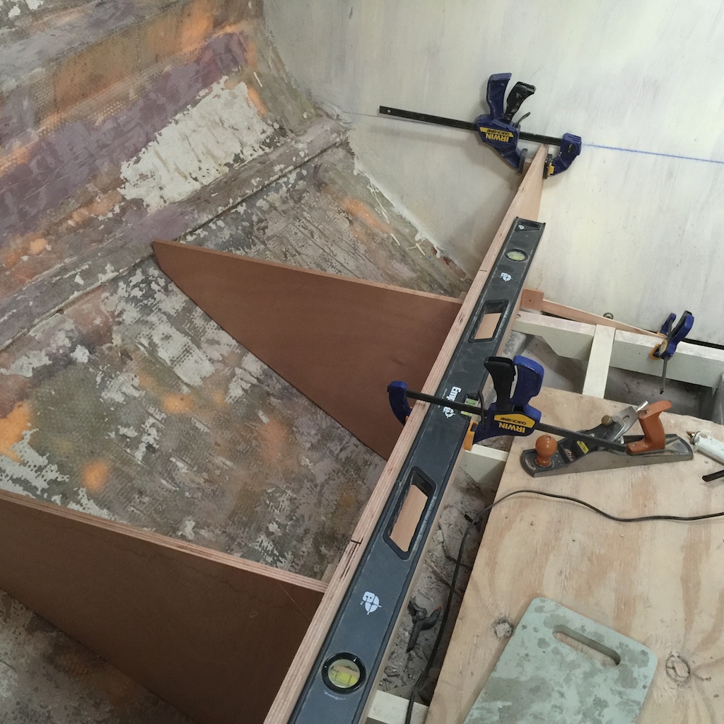
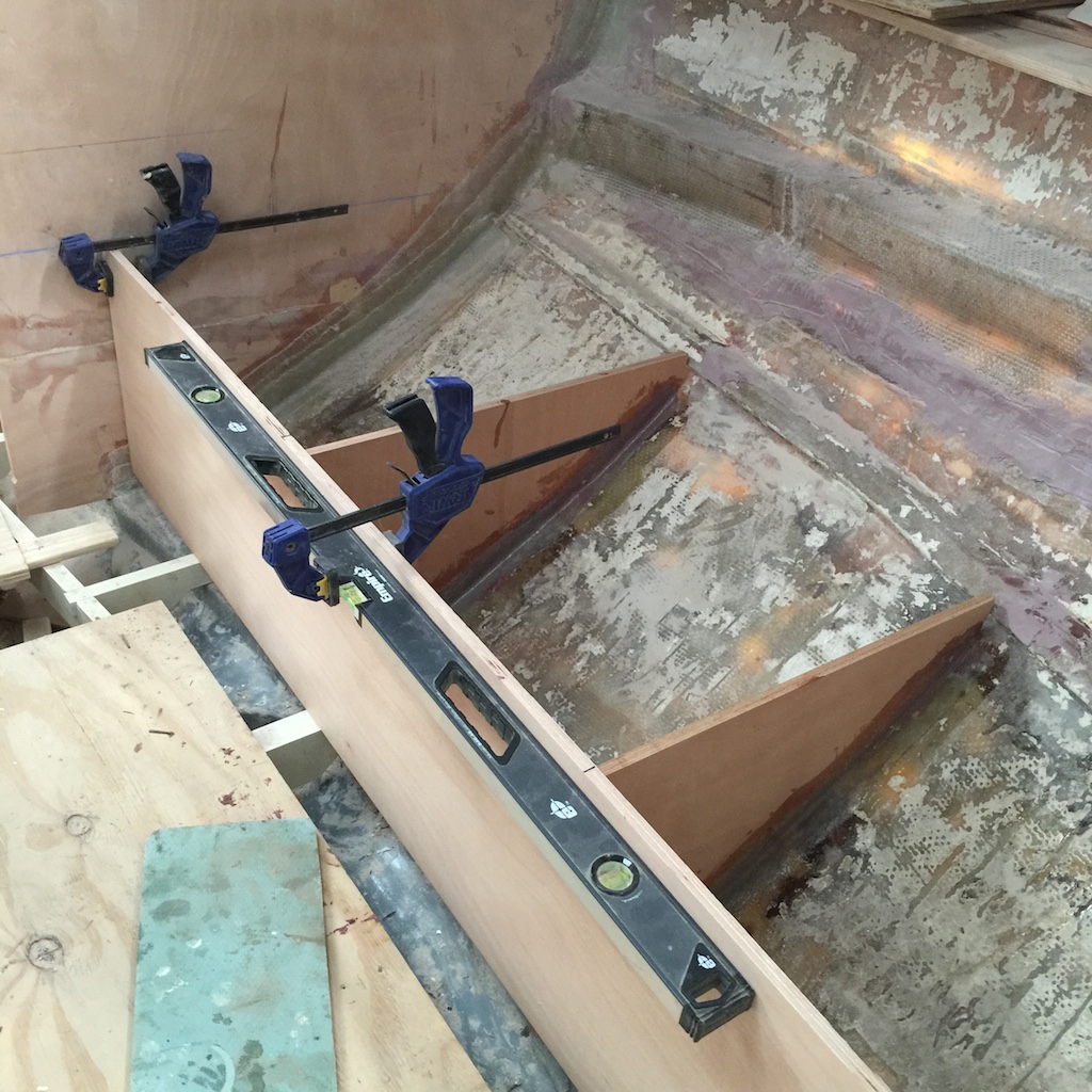
In the next photo I have run temporary horizontal battens at the shelf height to support the 5/8-inch plywood that will be shaped to the curve of the hull.
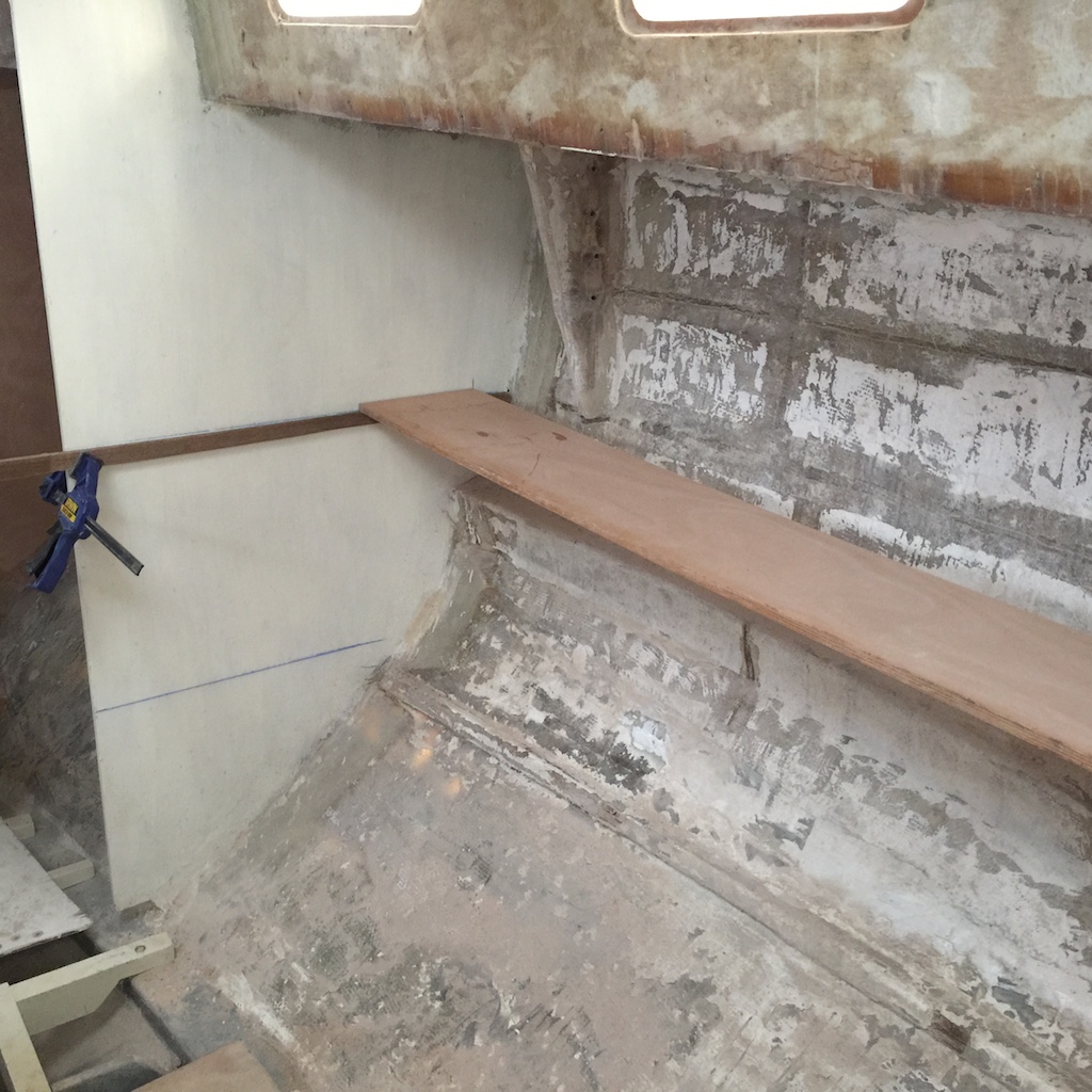
I positioned the board so that the outboard edge was exactly where I wanted the inboard of the shelf to be. Then, with a pointed stick and a marker, I was able to quickly mark the width of the shelf on the board. (After cutting, the shelve is “flipped over” so that the cut edge is outboard.)
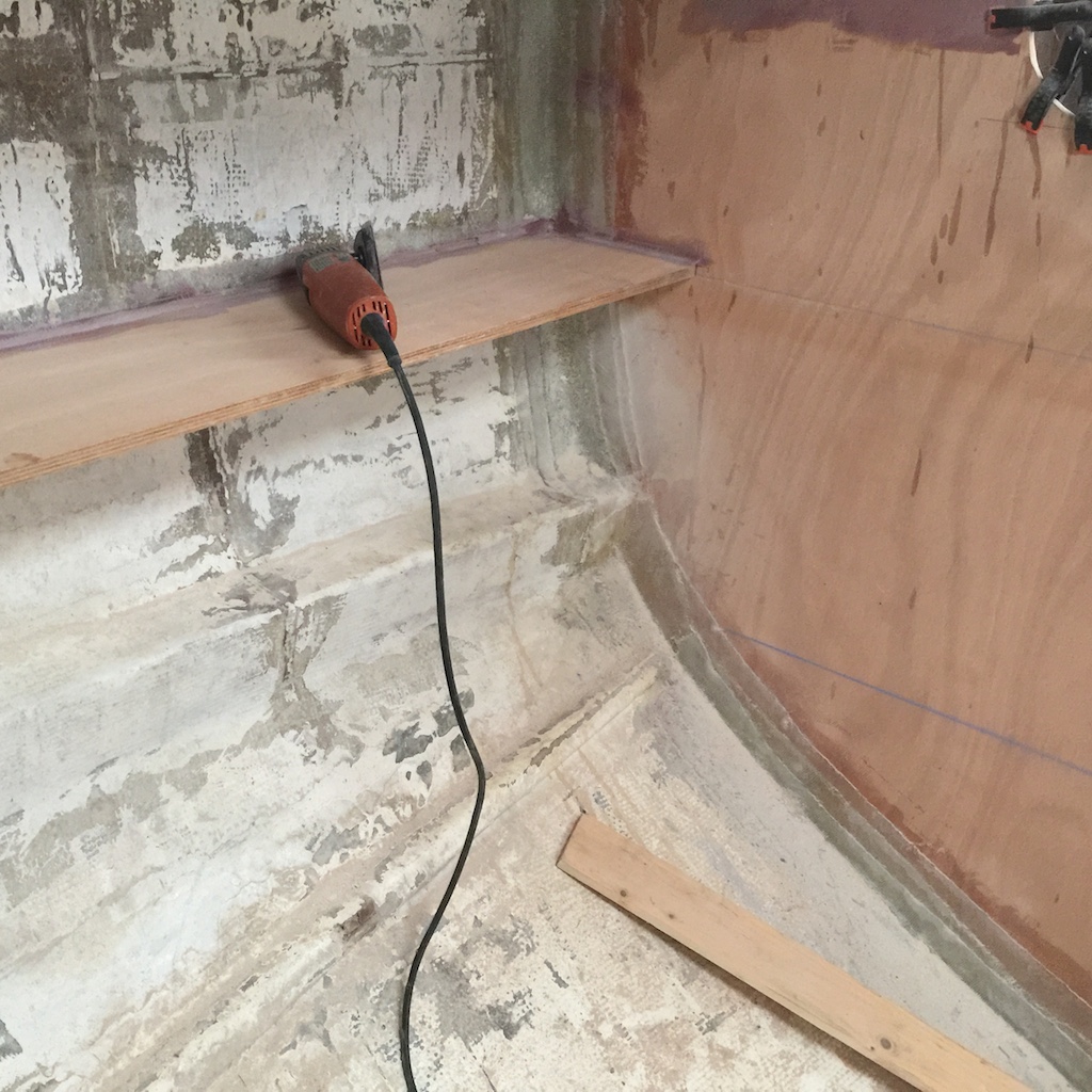
The dry fit included some glue blocks to remove the slight bow in the board due to the board’s weight.
As usual, a fillet of thickened epoxy was run along the edges, both above and below the shelf.
Next I made patterns for the shelf dividers. More on the shelf dividers later.
SEATS
The seat fronts will be 5/8-inch plywood (Okume unless otherwise specified).
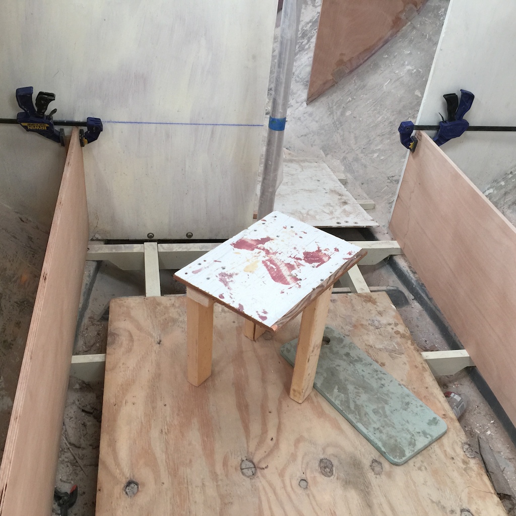
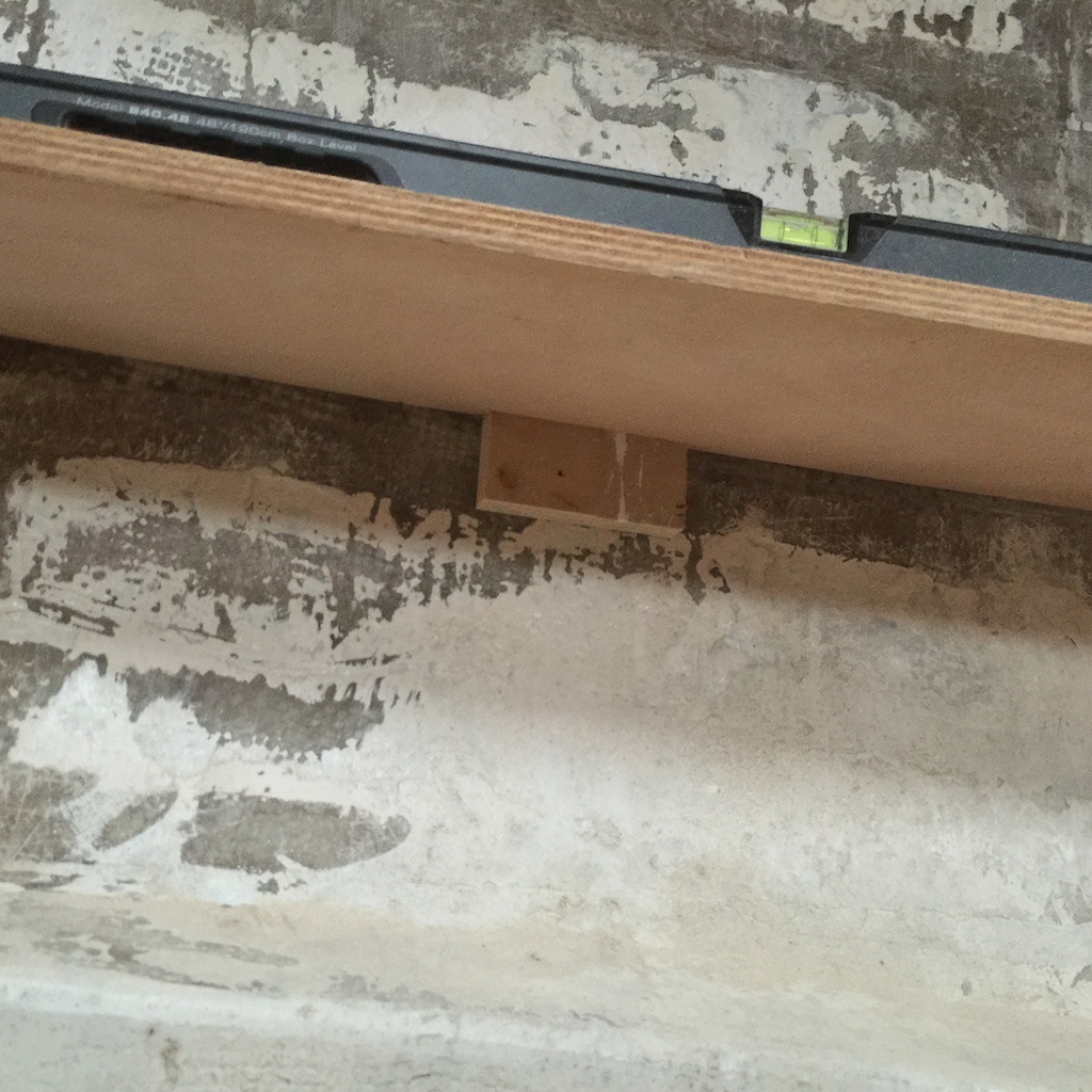
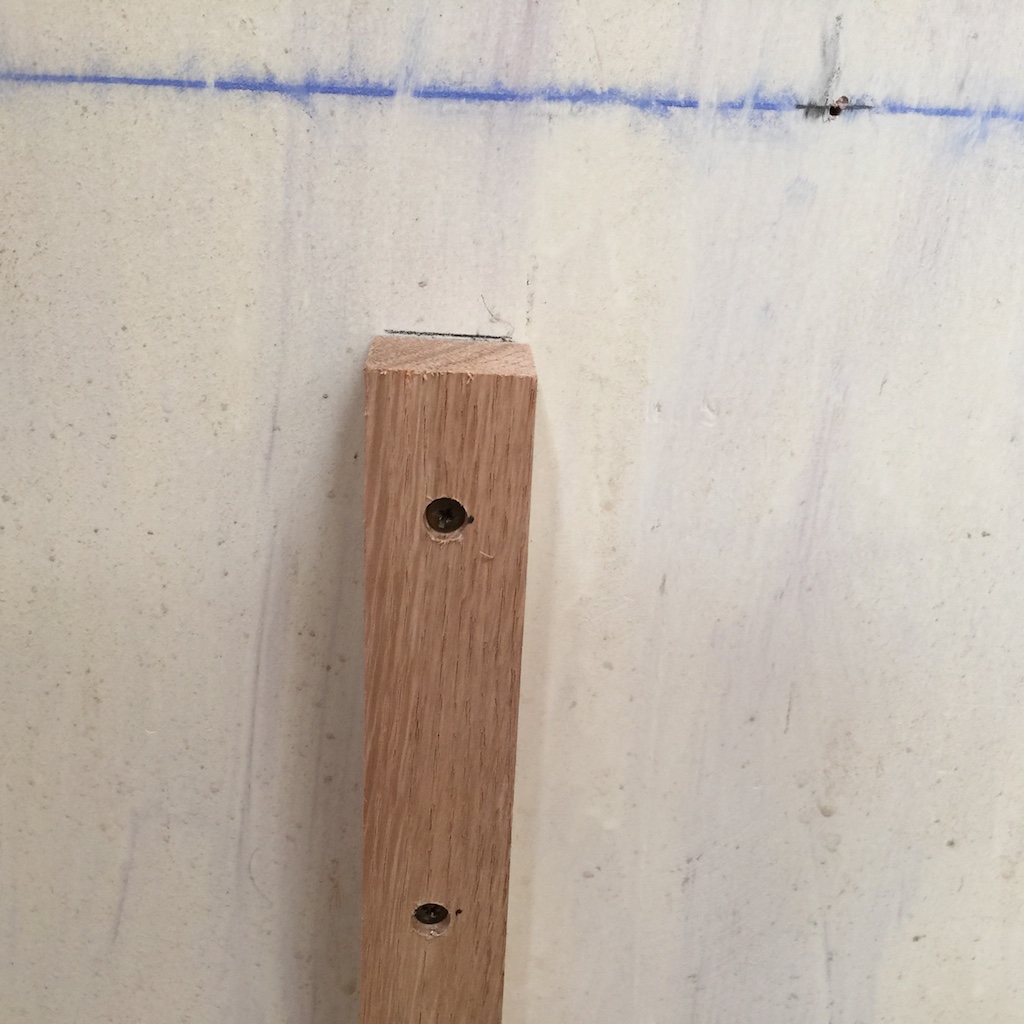
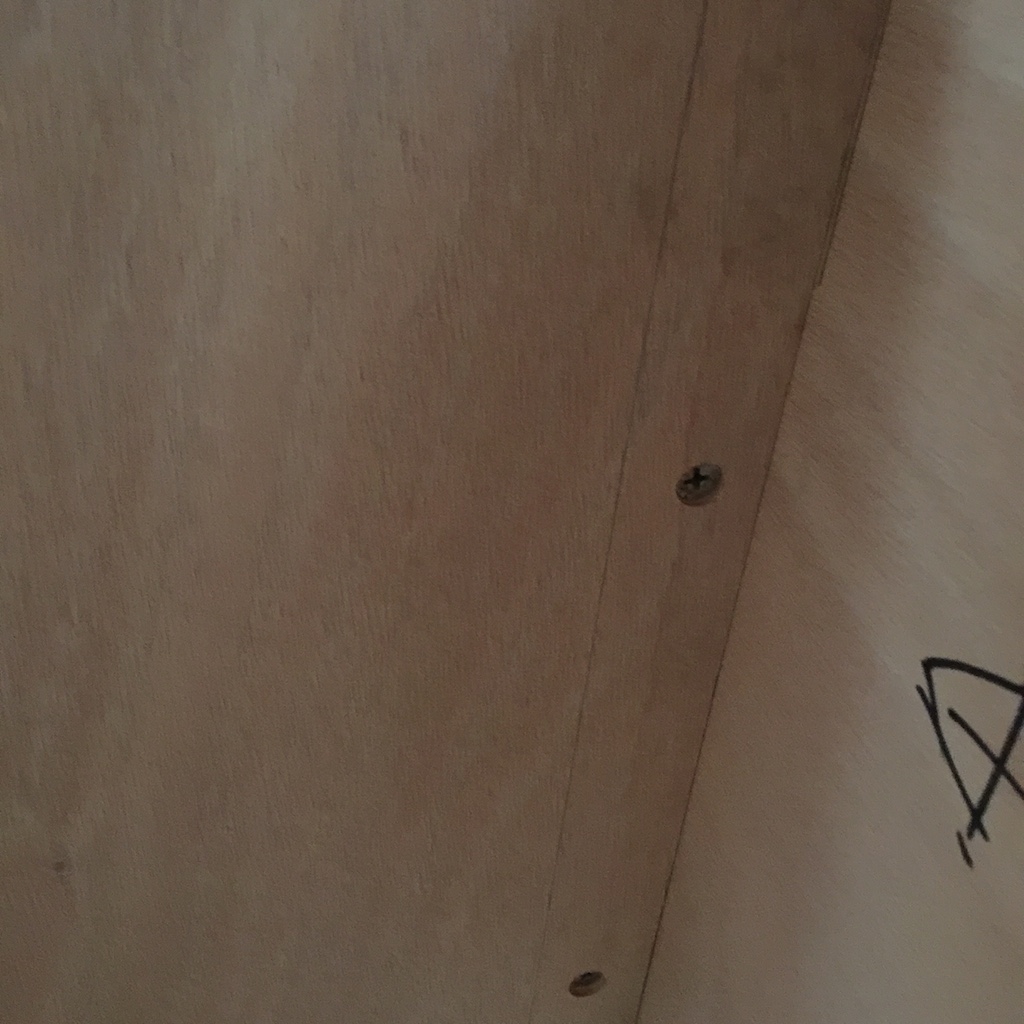
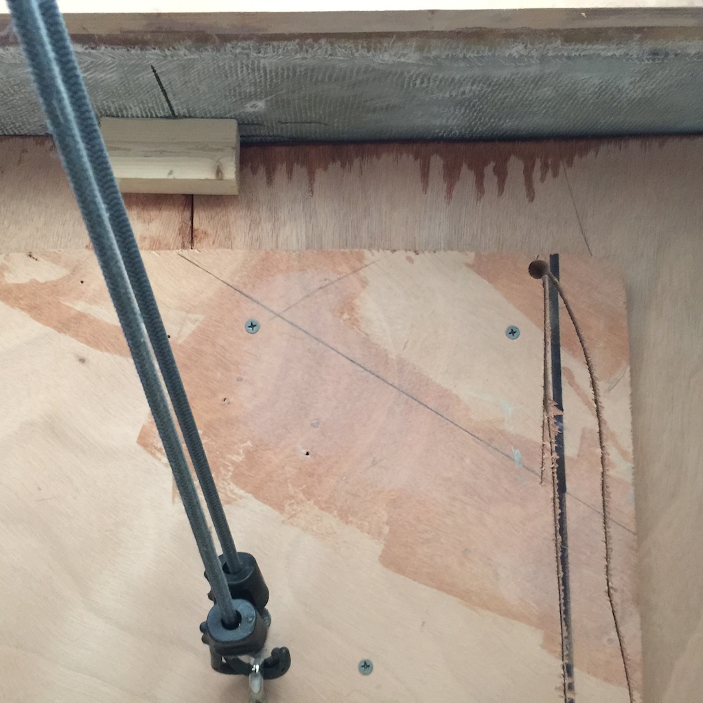
These board are 17 inches wide and I made a series of careful measurements to make them parallel and the same distance from the centerline. They are attached to the bulkheads with strips of wood called “cleats”. The cleats I used here are 1.25-inch square white oak in 14-inch lengths. The screw holes are countersunk and the following photo shows one of the cleats attached to a bulkhead.
I clamped the board temporarily to the cleats so that I could make patterns for the storage locker dividers. There will be two on each side, making three storage compartments under each settee bench. The original layout was five drawers and a too-small holding tank. Drawers can be serious space wasters when they close into a curved hull, which was my primary rationale for going with top-loading lockers.
The next photo shows the two locker dividers on the port side.
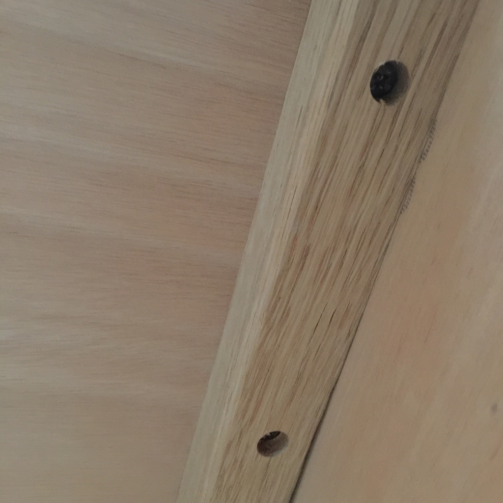
These dividers are attached to the seat fronts using white-oak cleats, and the following photo shows some of the details.
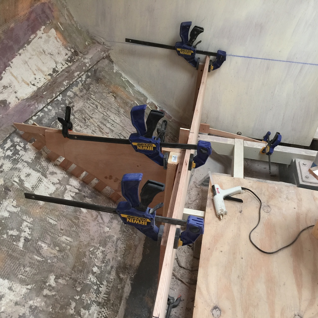
I bonded all four dividers to the hull using an epoxy fillet and one layer of fiberglass tape. When the resin cures, I will remove the fronts and continue by tabbing in the shelves.
AFT-COMPARTMENT BULKHEAD
I made the template for the aft-compartment bulkhead in the usual way, except that the working conditions under the cockpit and in the aft compartment are unusually cramped.
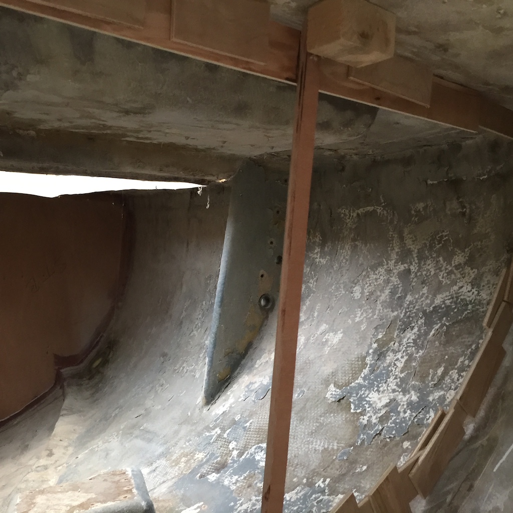
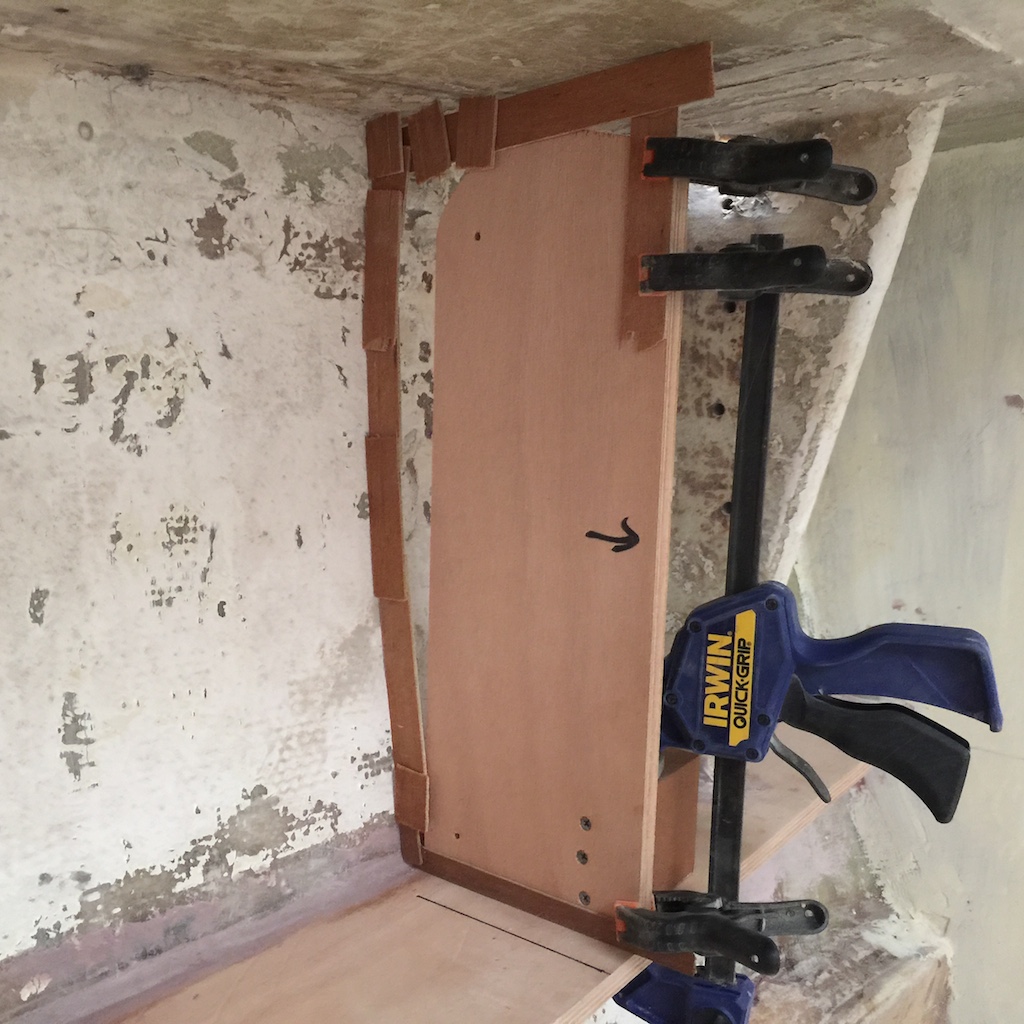
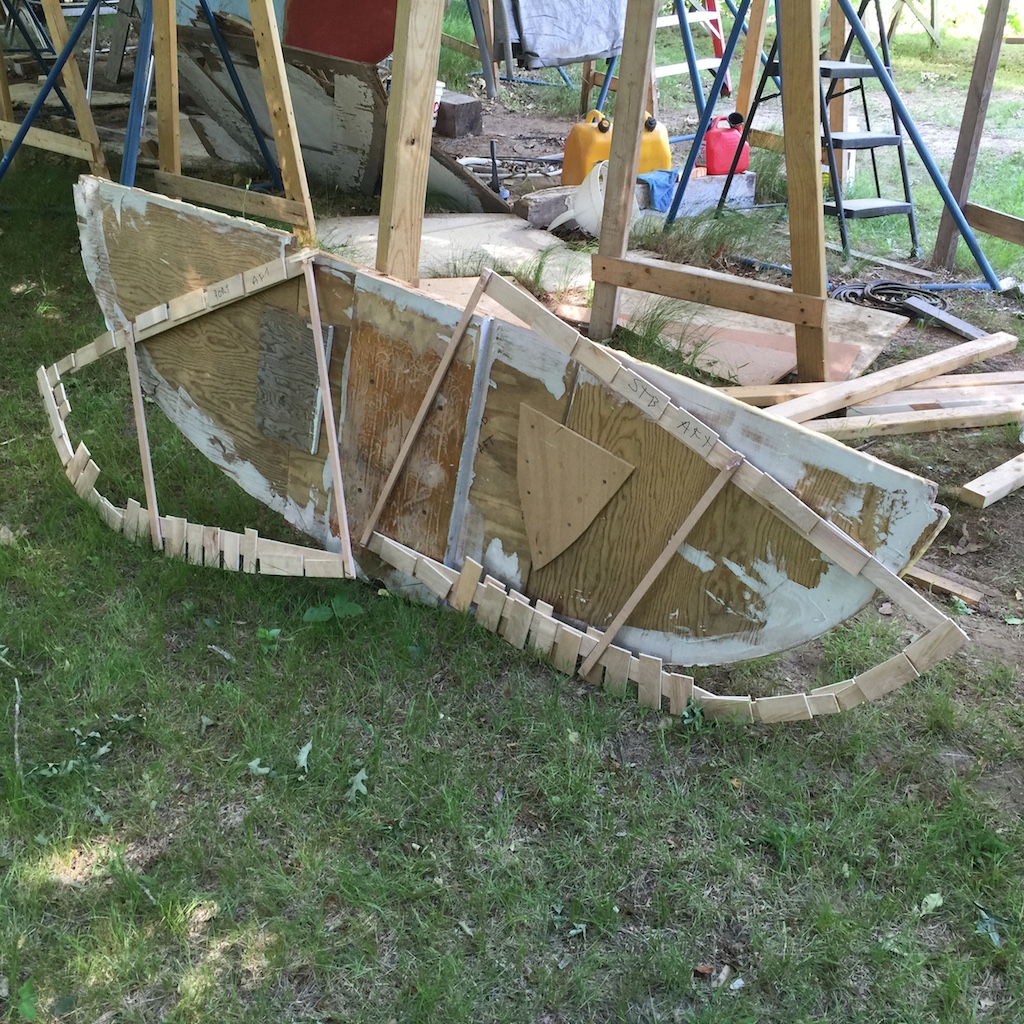
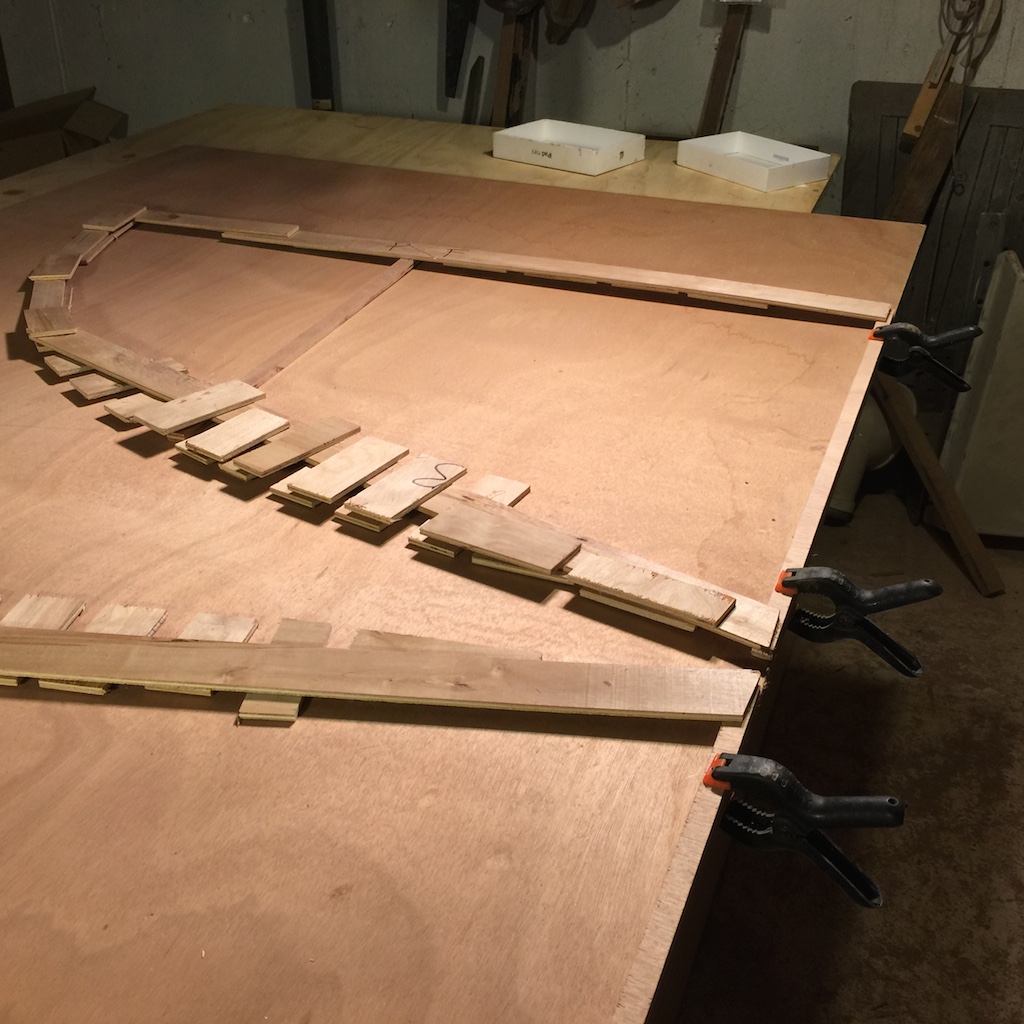
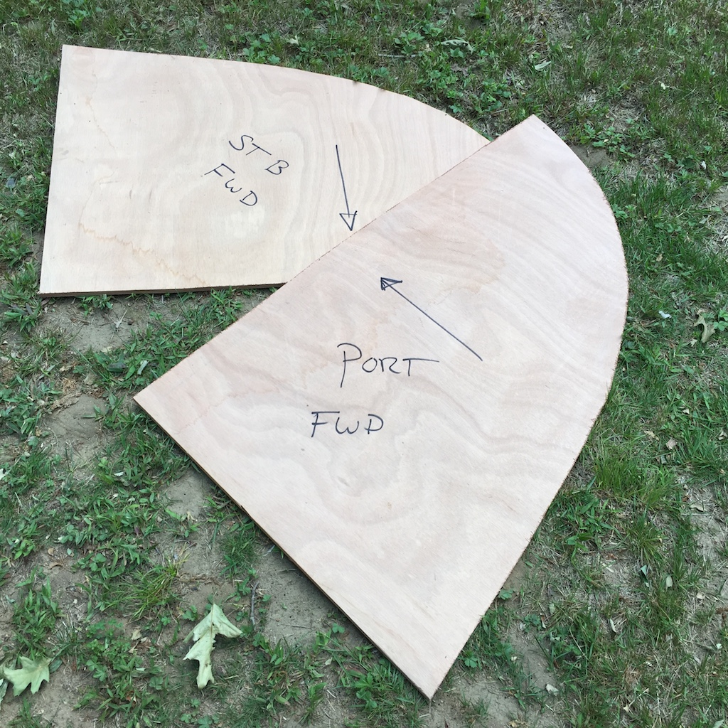
I made two patterns that meet at the centerline of the boat. Here you can see the completed patterns leaning on the old four-piece bulkhead and compression post.
These bulkheads are made from 1/2-inch plywood, which is about the same as the original, but I will be making and installing a compression post that will support the mizzen mast, so the area will be much stronger than the original.
The bulkheads were dry fitted and required no adjustments. I joined them at the center with some scrap plywood and used bungee cord to pull them against the glue blocks while I added an epoxy fillet along the forward edge.
After the forward-edge fillet dried, I added a fillet on the aft side, then bonded to the hull with two layers of biaxial cloth. There’s still quite a lot to do here, but the next step is to make pattens for the compression post.