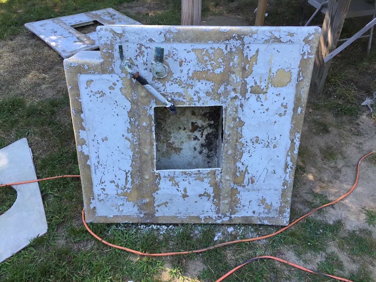
8/21/16: Holding Tank
The holding-tank project continues. I used a 5-gallon bucket and a hose to fill the holding-tank compartment.
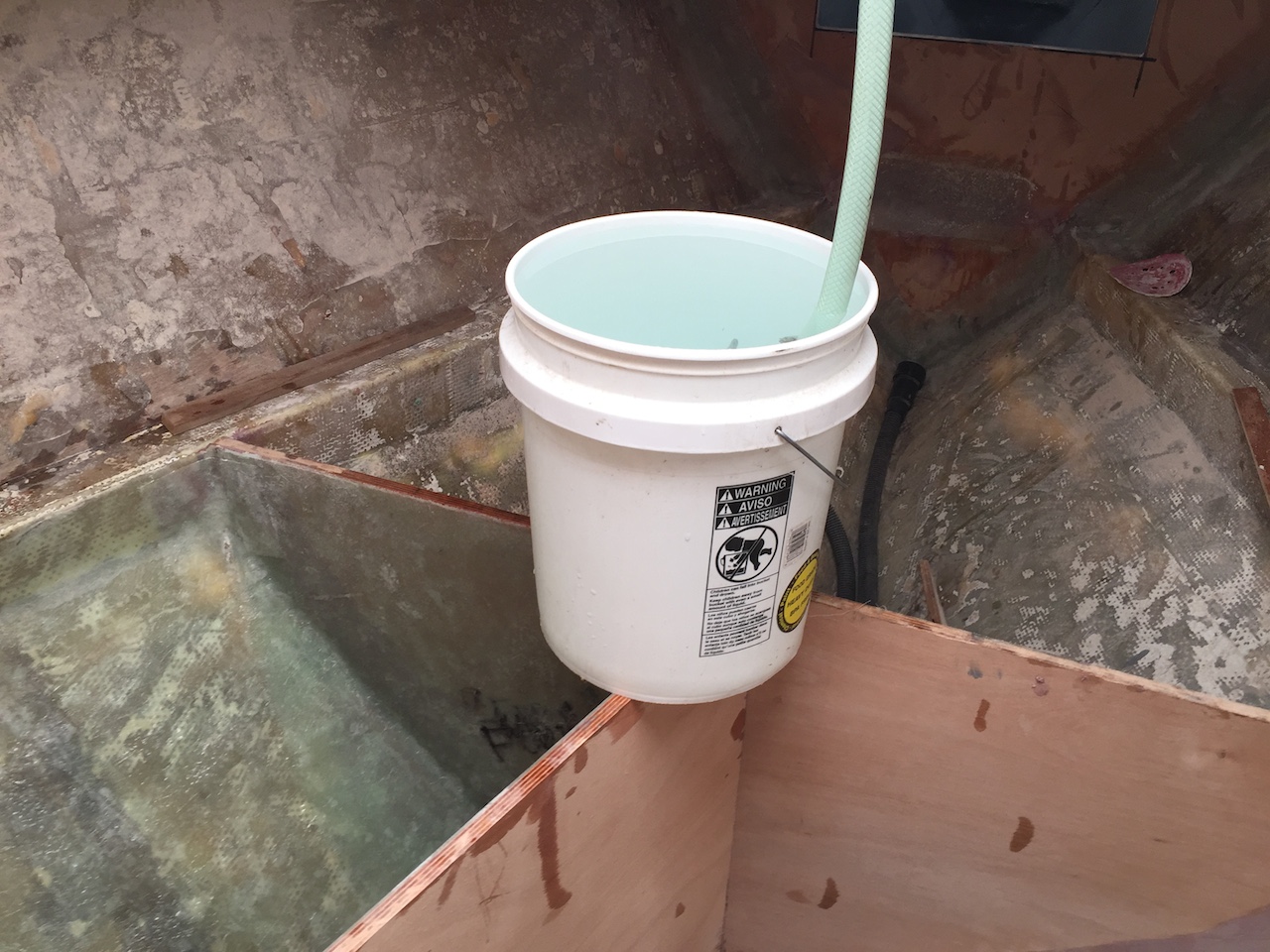
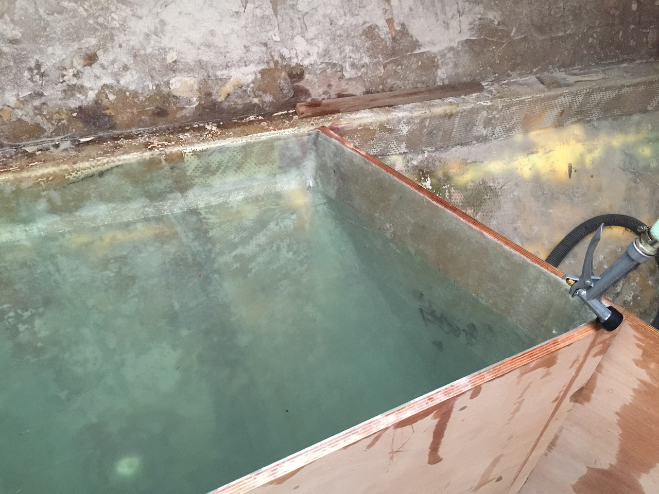
Eleven full buckets brought the water up to the level you see below, which I estimated to be at about the level of the bottom of the holding-tank top. Thus, the capacity of this holding tank will be about 50 gallons, which is quite generous by cruising-sailboat standards.
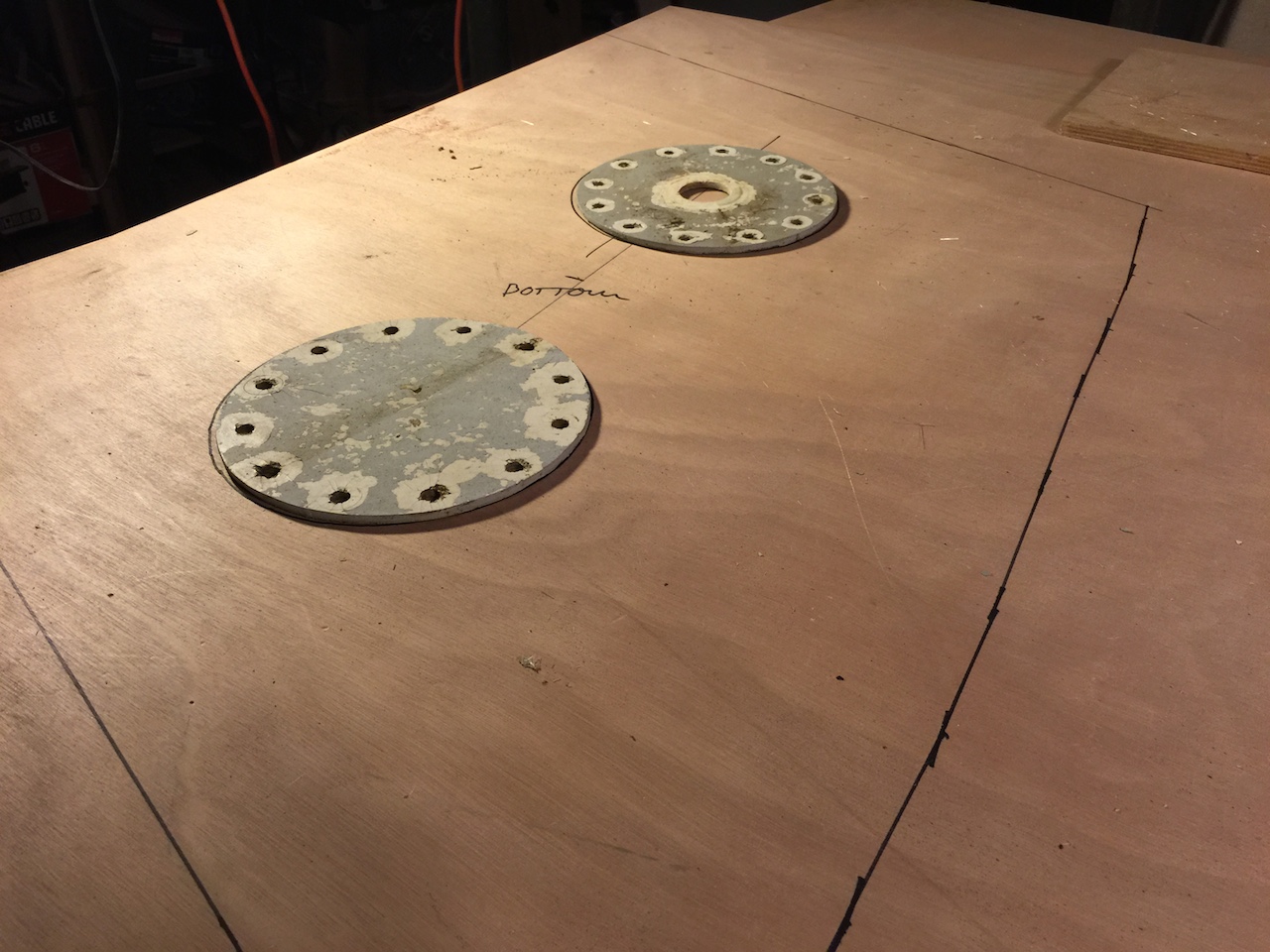
Next, I made a pattern for the top.
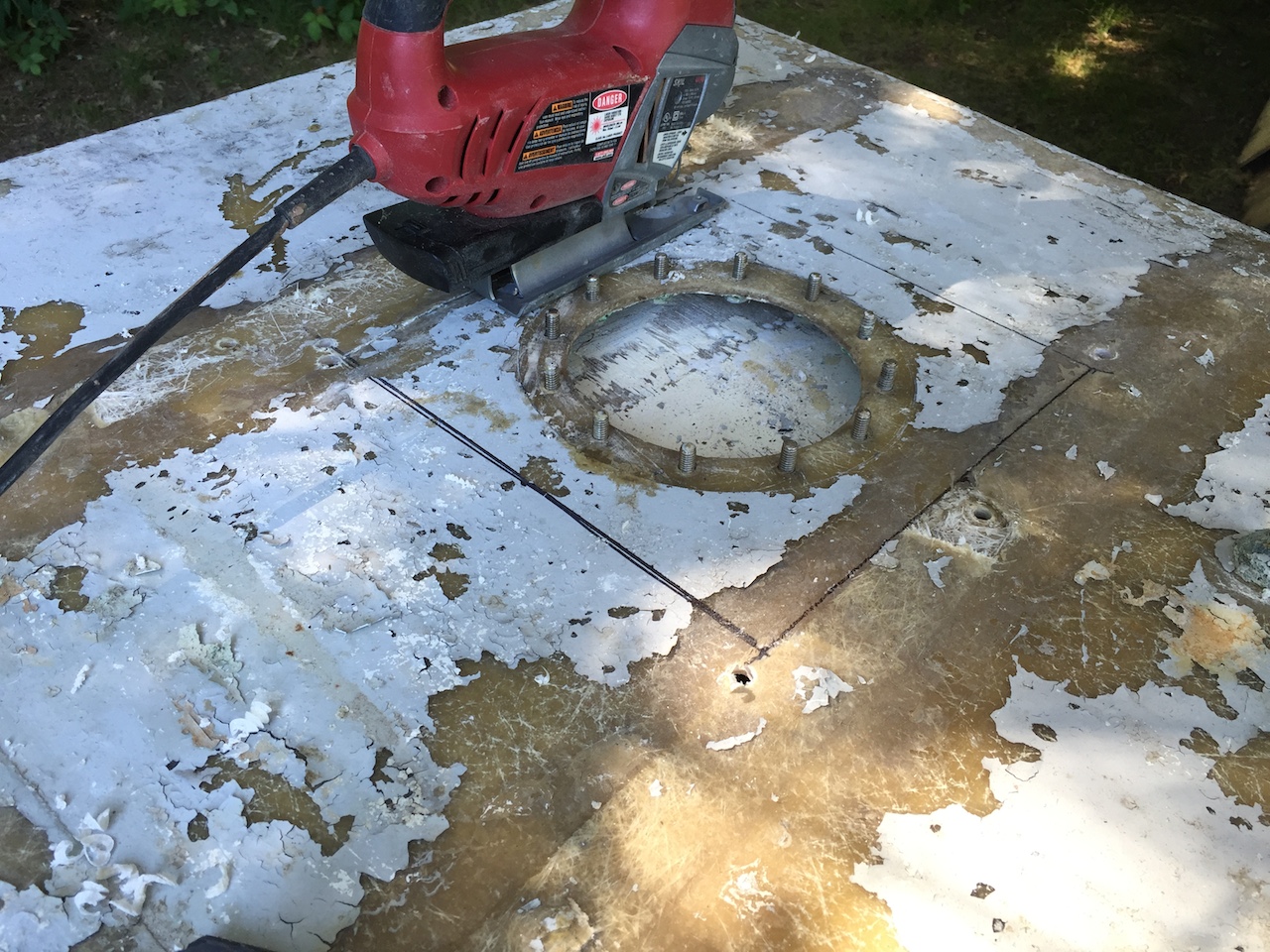
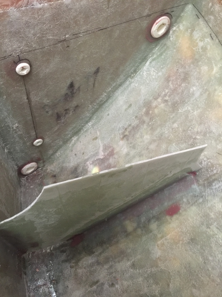
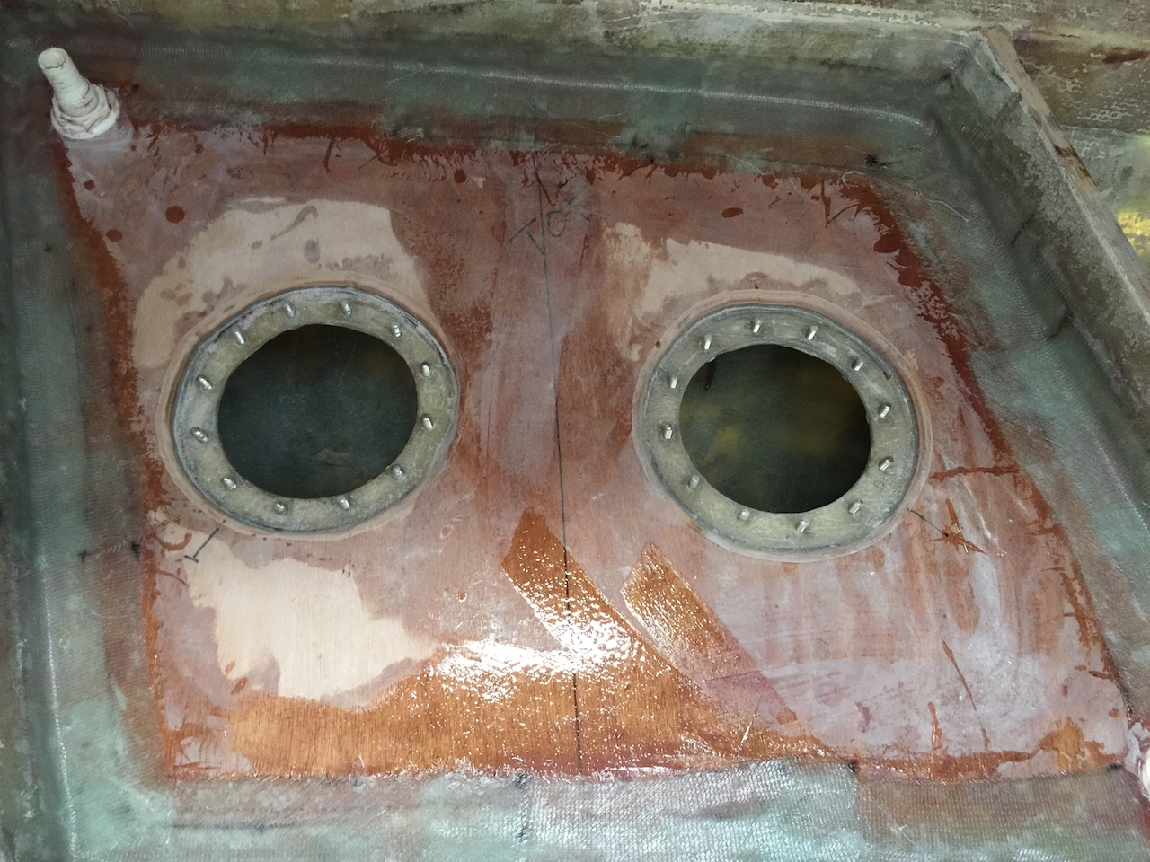
Next, I cut the inspection ports out of the old water tanks. These will be the inspection ports for the holding tank.
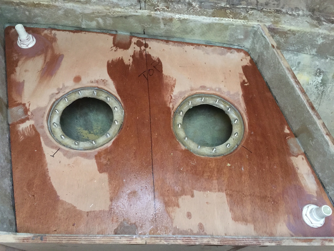
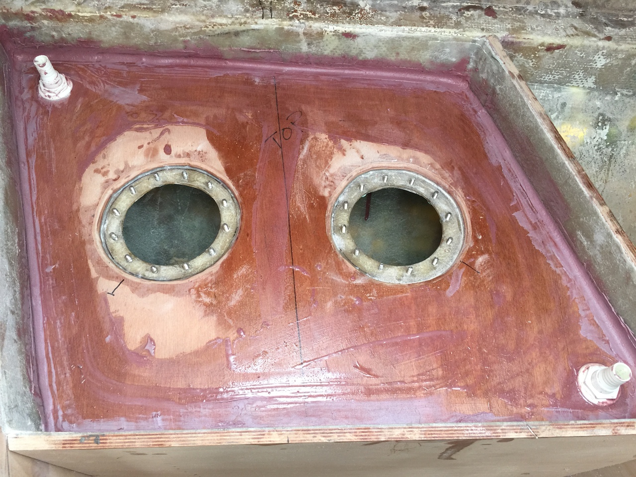
The pattern was traced onto 1/2-inch plywood, then the covers for the old inspection ports were used to trace out holes for the inspection ports.
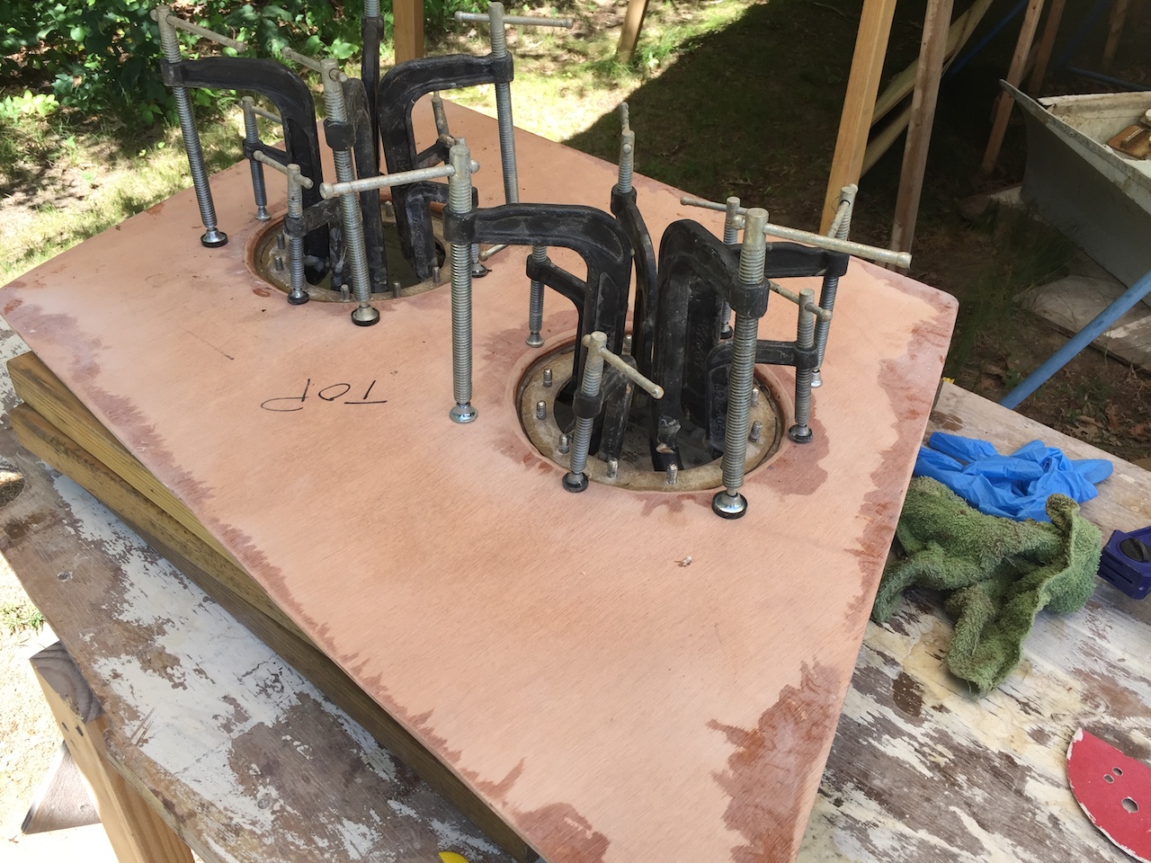
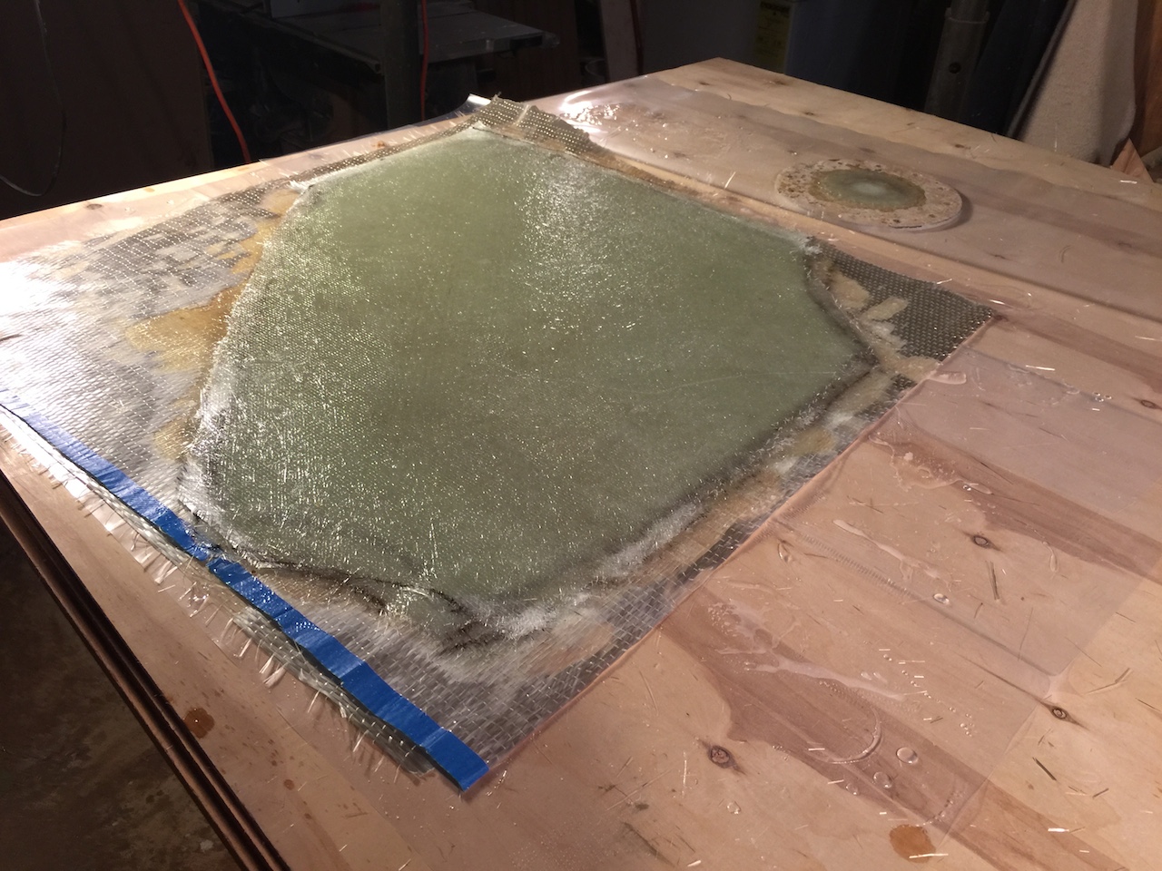
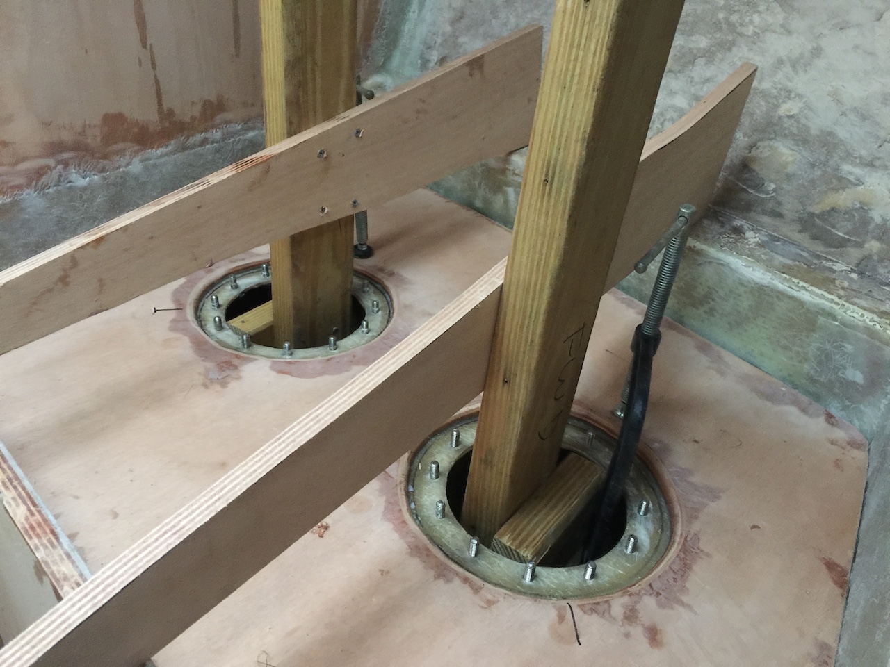
The bottom of the top received three layers of fiberglass (not shown), then the inspection port cutouts were bonded to the top with thickened epoxy. The clamp-up is shown in the following photo:
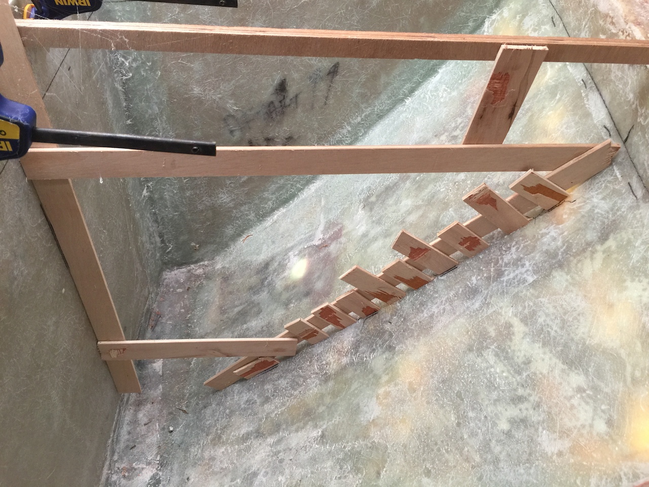
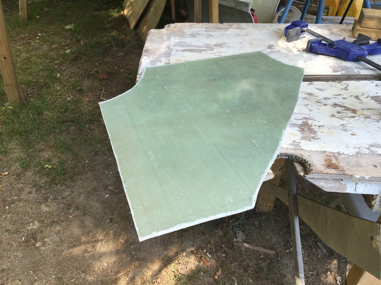
Next I made a pattern for the baffle, which I used to make a template for the baffle.
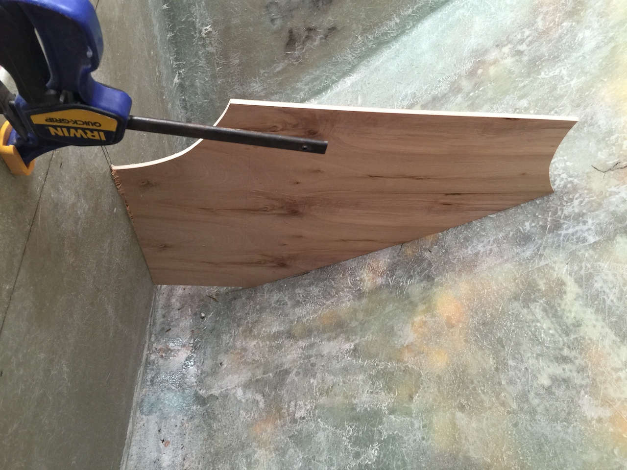
I made the baffle by laminating six layers of fiberglass (some mat, some biax, some unidirectional).
The next photo shows the baffle cut to its final dimensions. (Incidentally, all this cutting of fiberglass was done with a jigsaw. Glass quickly destroys sharp steel edges and I went through perhaps 10 blades in all this work.)
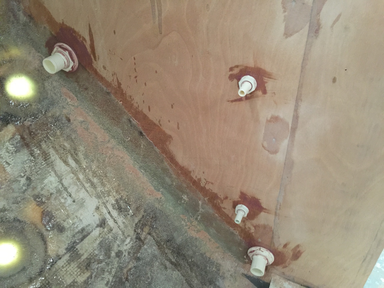
The plumbing requires six fittings: Two for pump in and pump out (the larger fittings below). Two for a level gauge (the smaller fittings below). Two for vents (not shown). The “in” fitting was placed high and close to the hull. Placing it close to the hull prevents a long drop for whatever enters the tank and should minimize splashing noises. The “out” fitting is, of course, as low as possible. The gauge fittings are one above the other. The gauge will simply be a clear tube that leads from the upper to lower fitting. The level of fluid in the clear hose is the level of fluid in the tank. More on the gauge later.
Here the baffle is glassed in on two of its three sides and we can see the interior ends of the fittings.
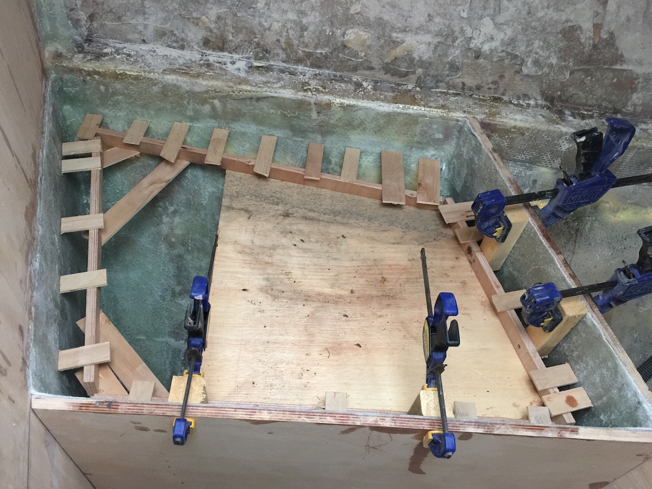
The next photo shows the way in which I kept the top in position so that it could be tacked into place.
Here the top is tacked into place with four small fiberglas glass tabs. Next, I tabbed the underside edge of the tank using small fiberglass strips.
With the tank edge sealed, I filled the gap around the edge with lightly thickened epoxy and, when that dried, then a fillet of thickened epoxy
Finally, I sanded the fillet and the top and applied two layers of glass tabbing.
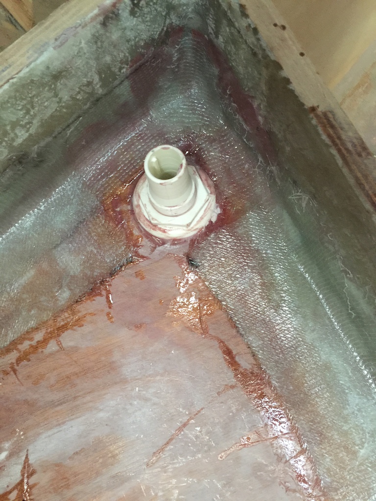
Note the tank vent fittings in the previous photos, which are installed in the top. These are 1-inch fittings, which is very generous. The primary purpose of a holding tank vent is to allow gaseous contents to escape when waste is pumped into the tank, and also to allow air to enter the tank when the tank is being pumped out. Less venting is generally sufficient for that purpose, but I am going with two generous vents two reasons:
(1) Two vents will allow cross ventilation, which greatly reduces tank odors by allowing aerobic bacteria to do most of the work in breaking down waste. The by-product of aerobic bacteria’s work is odorless carbon dioxide. Without the oxygen provided by cross ventilation, anaerobic bacteria does much of the work, and the by-product in that case is a variety of odor-ful gases, like sulfur dioxide.
(2) Note that one of the vent fittings is inboard, which the other is outboard. When the tank is partially full, and the boat is heeling, then one vent will be under the level of the tank contents, but the other will definitely not be. Thus, if someone pumps waste into the toilet while sailing, there will always be good venting.