5/22/17: Forward Cabin
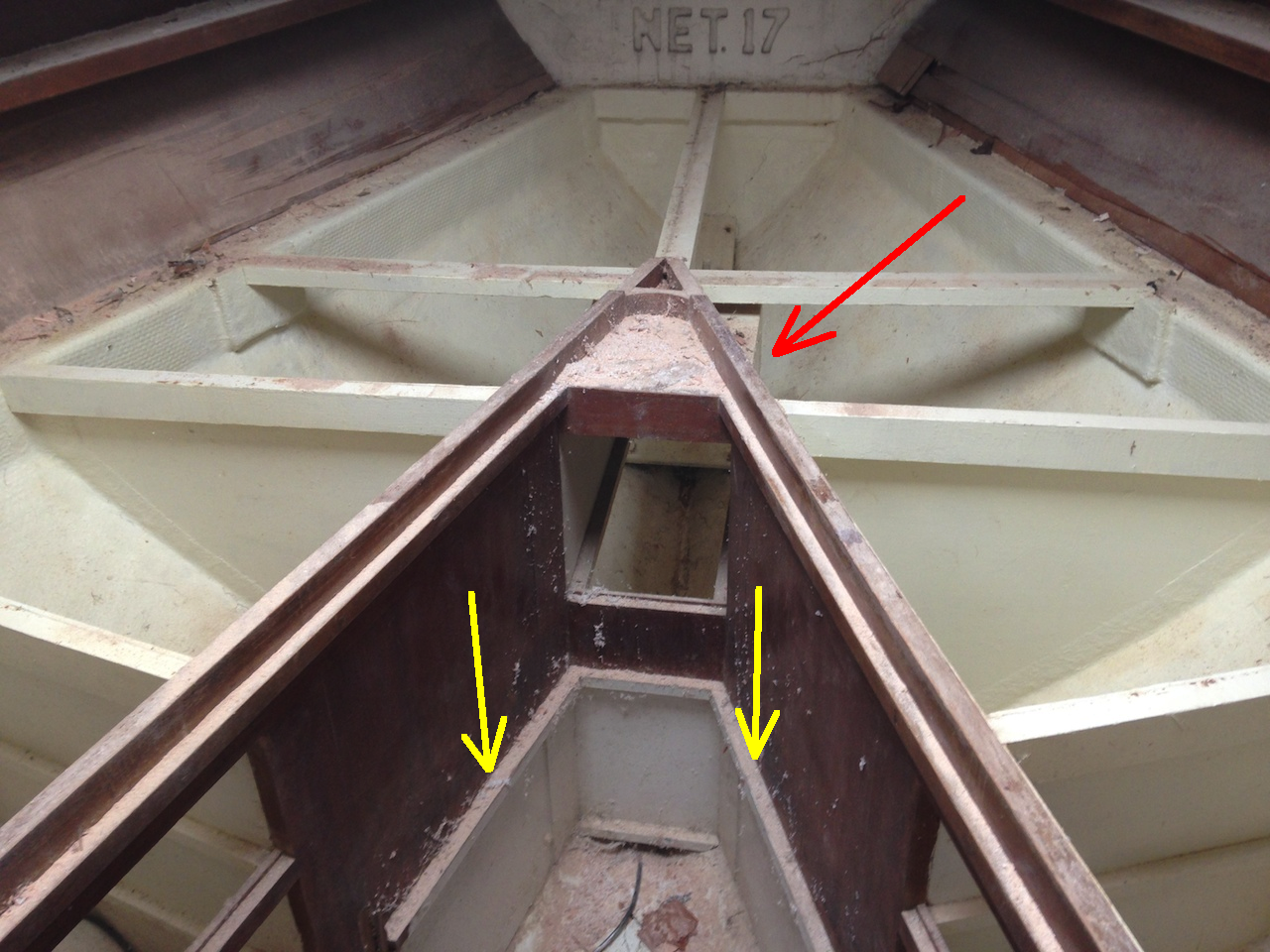
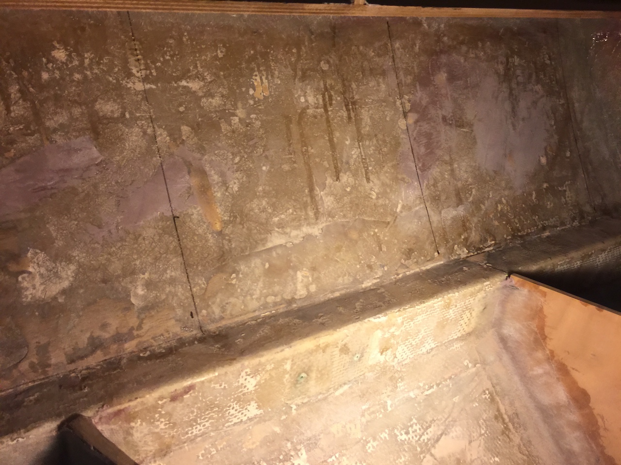
In the forward cabin, the holding tank, bulkheads, and structural pieces of the storage shelves have all been completed, but not finished. Recall that the forward cabin was redesigned to be asymmetric, with a wider bunk on the port than the starboard. Recall also that the original forward cabin, pictured below, had several small drawers that were real space wasters. The yellow arrows show where the drawer there stole space from the floor, while the red arrow shows where a small drawer stole storage space from under the bunks.
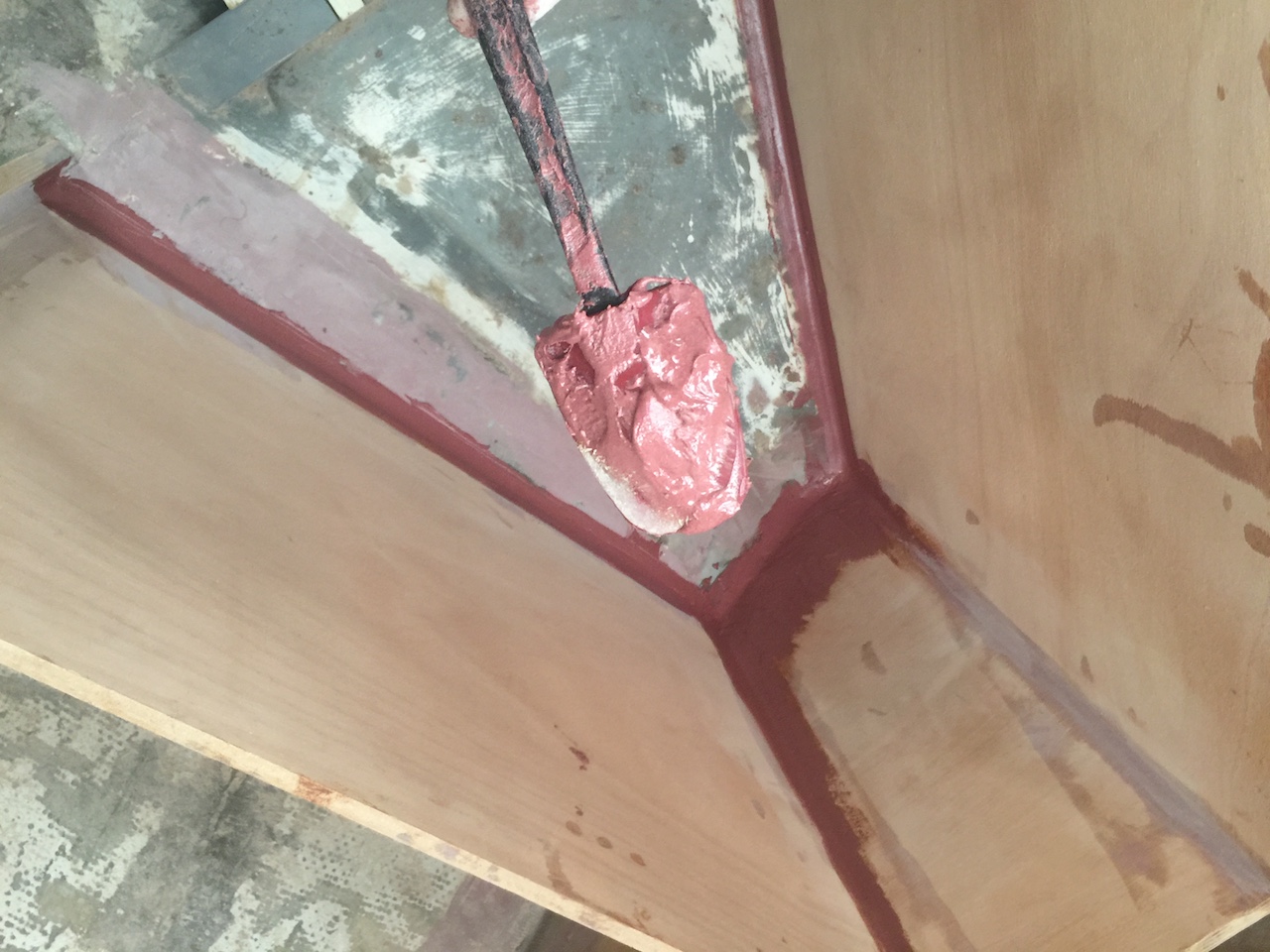
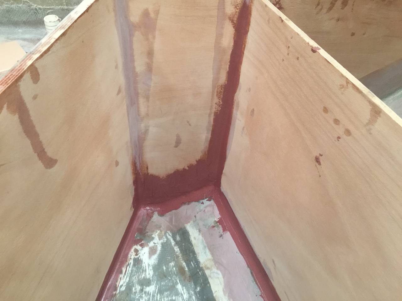
Work resumed by using thickened epoxy to make generous fillets to dress the intersection of various surfaces.
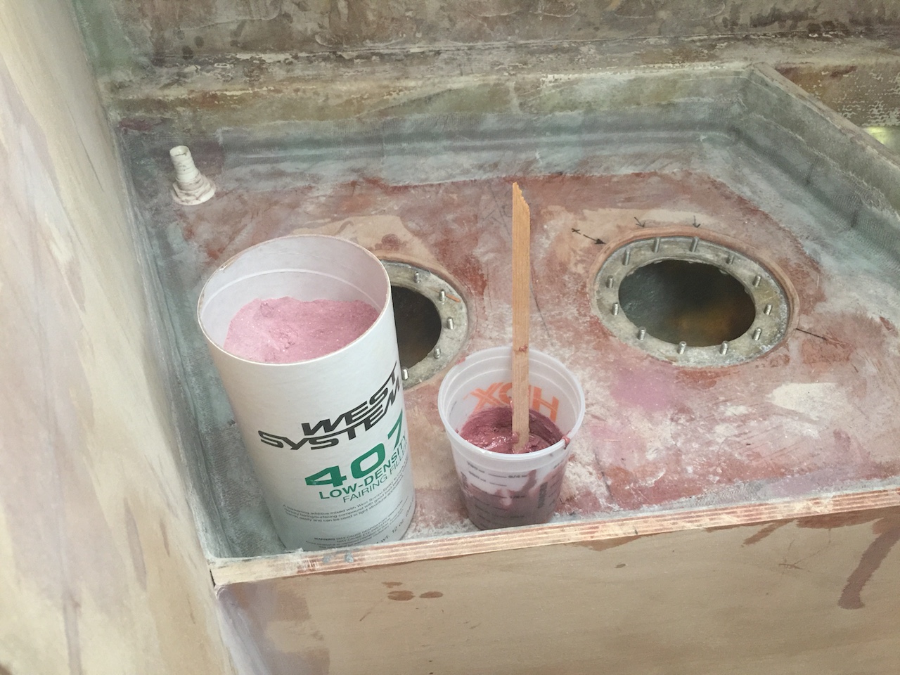
A cheap food spatula was an ideal tool for making large-radius fillets
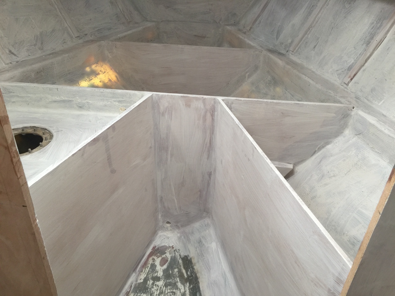
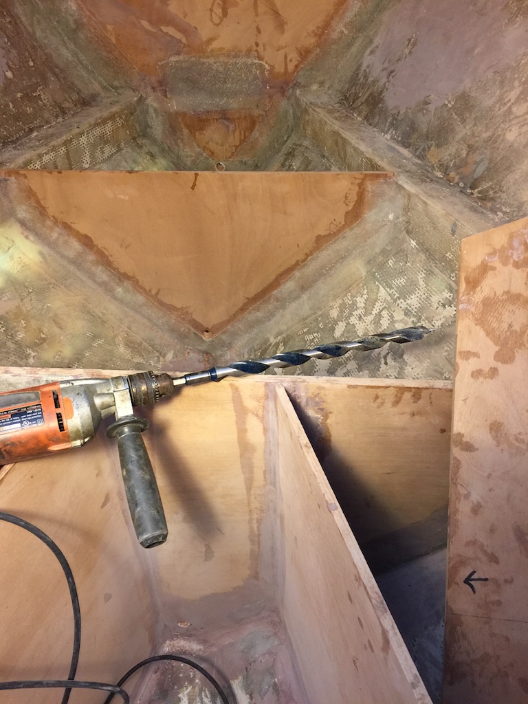
In the image below we are looking forward, with the holding tank on the left and a storage locker on the right.
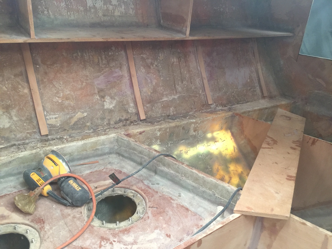
The 1-inch auger bit was employed to make the limber holes that will prevent the accumulation of water where it is not wanted.
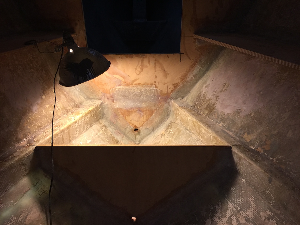
The limber hole we see in the image below will eventually have a plug that can be closed in case of an emergency. I learned from Ben Stavis that the forepeak bulkhead is a so-called “collision bulkhead.” The bottom of the opening is above the water line. In the event of a collision causing a hole in the forepeak area, then, water entering the forepeak area should not be able to flow back into the main cabin.
Next, thought about the hull covering in the forward cabin. Originally a thin, veneer-covered wood was glued to these areas (see photo with the arrows above). My plan is to use 1/4 inch marine plywood, painted white or, perhaps, tongue-and-groove strips In any case, I want this covering to be removable, so I glued up 3/8-inch vertical support strips, five on a side, to which the covering may be screwed. The photo below shows vertical lines marking the eventual position of a few of the strips.
The difficulty, of course, is getting the rigid strips to take the bend of the hull while the epoxy dries. The photo below shows how I applied the pressure using scraps of wood and clamps.
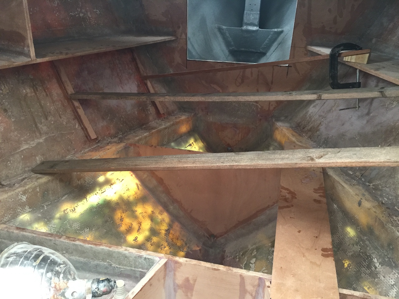
The scene in the photo above might seem relatively serene, but it was, in fact, a moment of relative panic. I had forgotten, as I have forgotten before, that the friction that is present during the “dry fit” can be largely nonexistent during the “wet fit.” Getting the strips to stay put under so much pressure required a lot of adjusting the angle of the clamping and inserting temporary spacers. The picture below shows the improved technique I used on the starboard side.
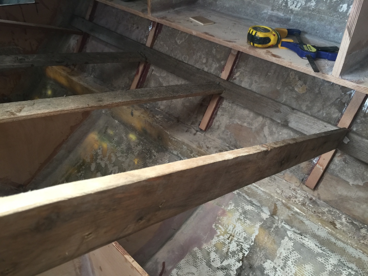
The next photo was taken after the clamping had been removed.
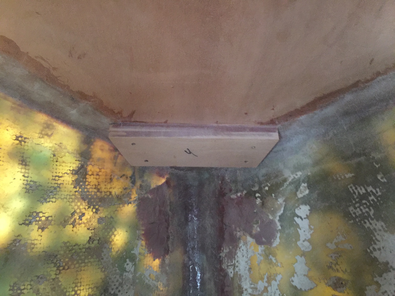
Next, I used some scrap marine plywood to glue up some wide cleats that will support the “floors” in the under-bunk storage lockers. More on this later, but there were no floors here in the original layout.
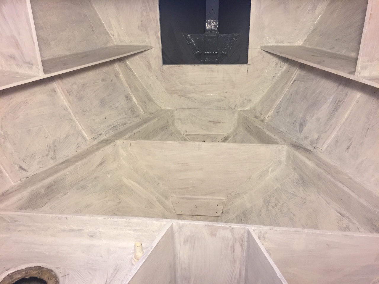
Finally, after cleaning and sanding, I applied a coat of white primer, which will highlight areas that need more attention and serve as a foundation for more primer and, eventually, paint.