9/1/17: Galley and Head Area
The picture below is from 2007 and shows the original head layout, where we can see that the sink cabinet is outboard and the countertop is small in area.
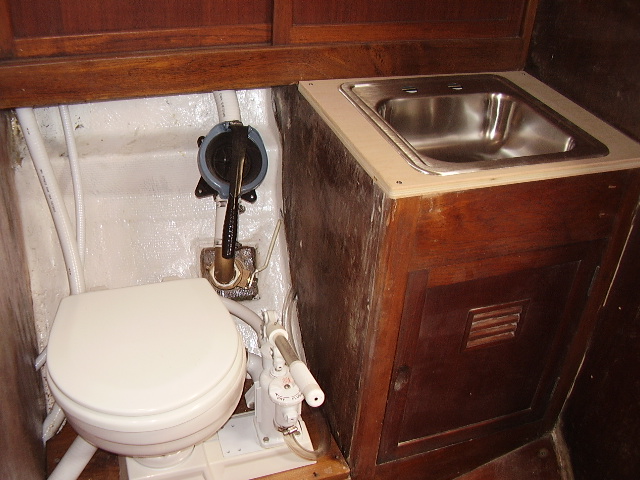
OLYMPUS DIGITAL CAMER
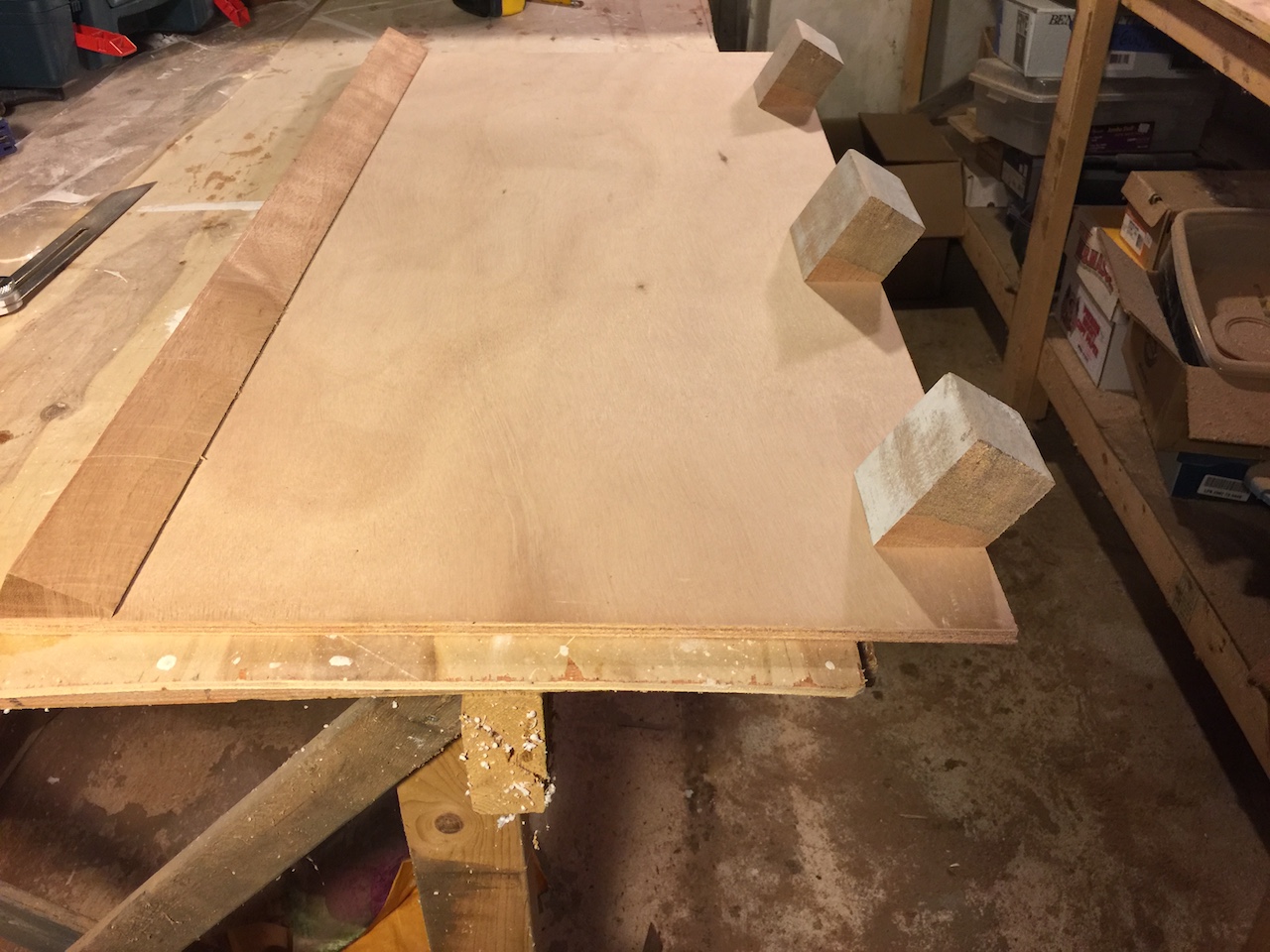
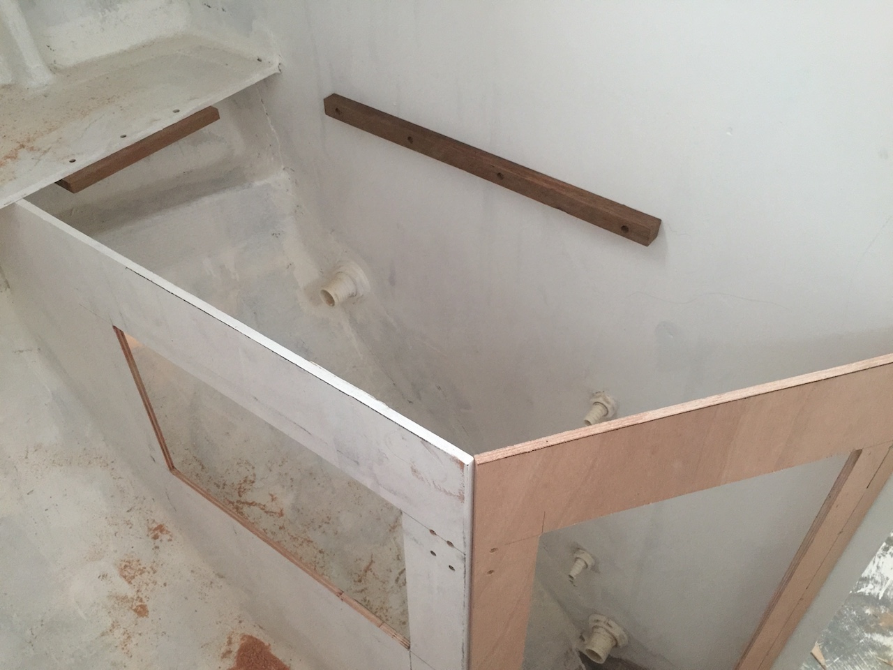
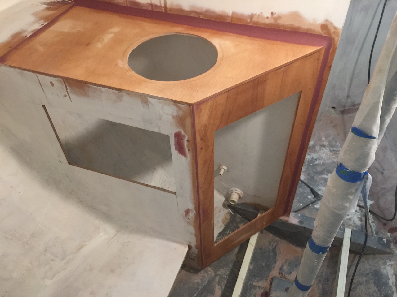
The new design of the head compartment permits an improved layout, where the countertop can extend further inboard. My next task was to finish enclosing the under-sink space, and the following photo shows a rectangle of plywood, onto which I have screwed angled blocks which will be screwed to the adjacent bulkheads.
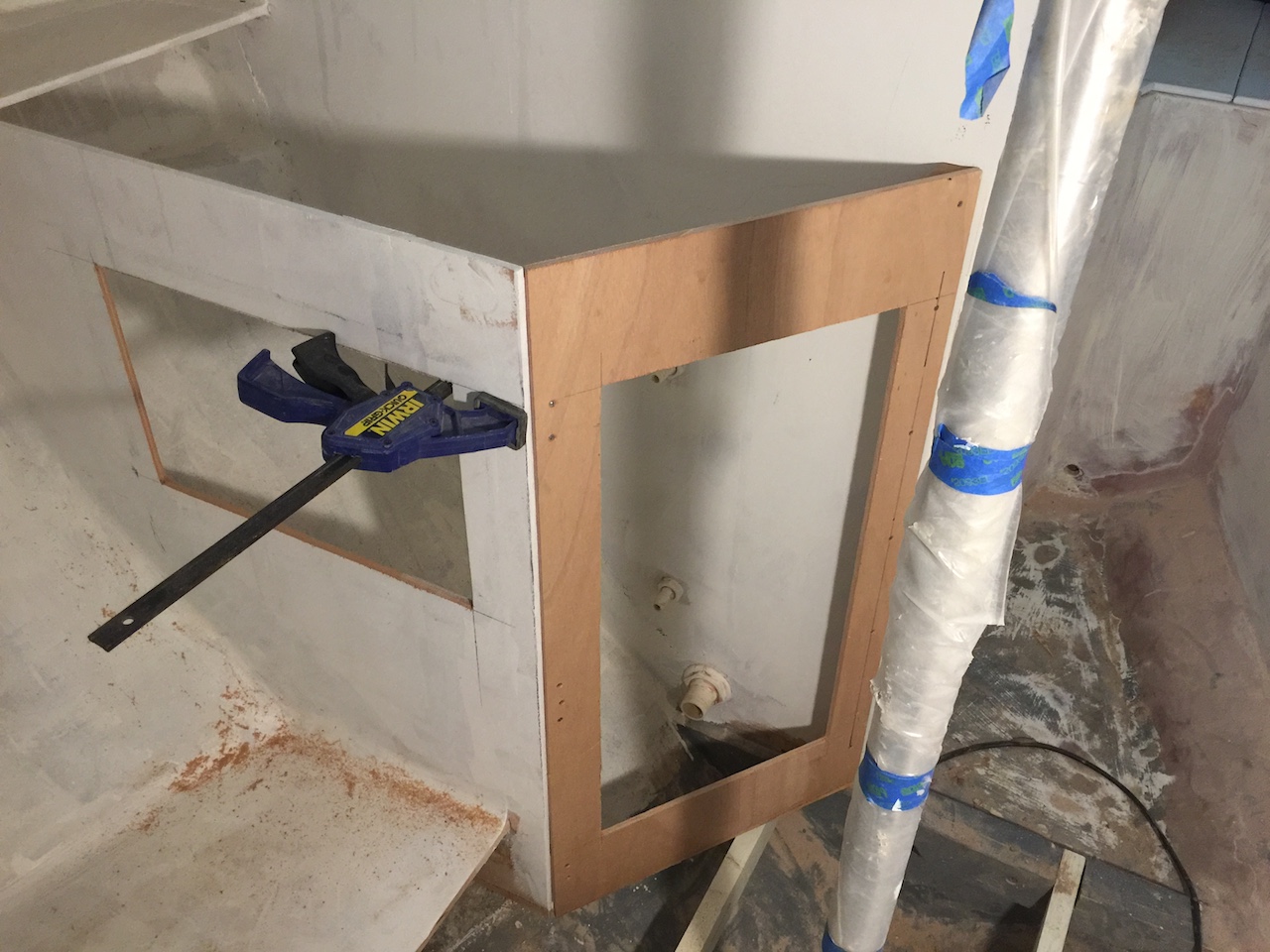
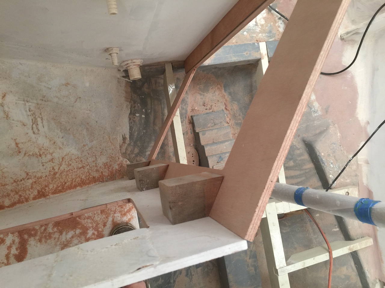
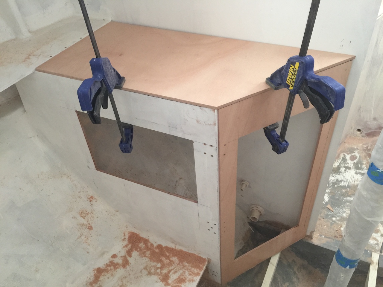
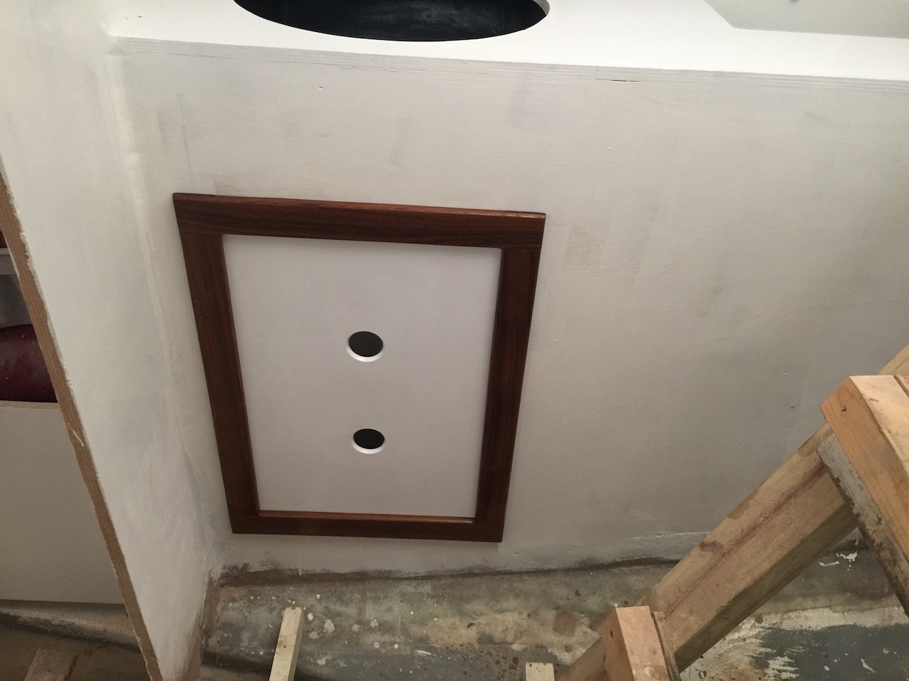
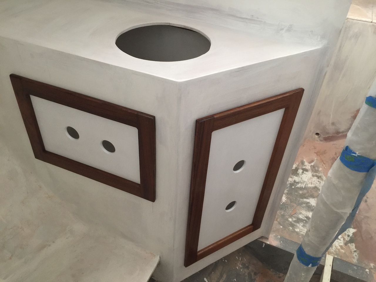
The next three photos show the assembly, where you can see that I’ve cut generous access ports. This under-sink area is not storage space–it will contain a through-hull, plumbing, and possibly a manual pump.
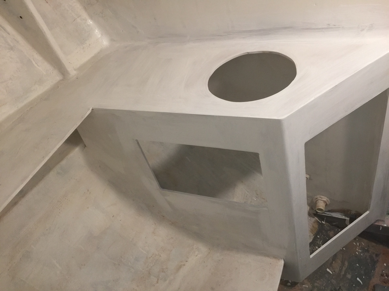
Next, I added two horizontal teak cleats that will support the countertop.
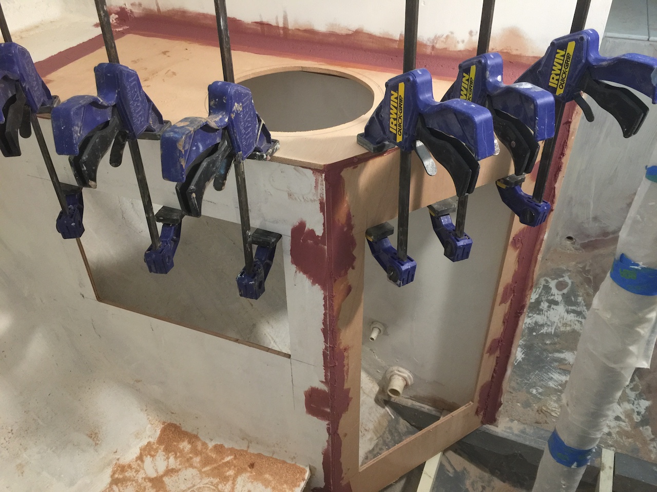
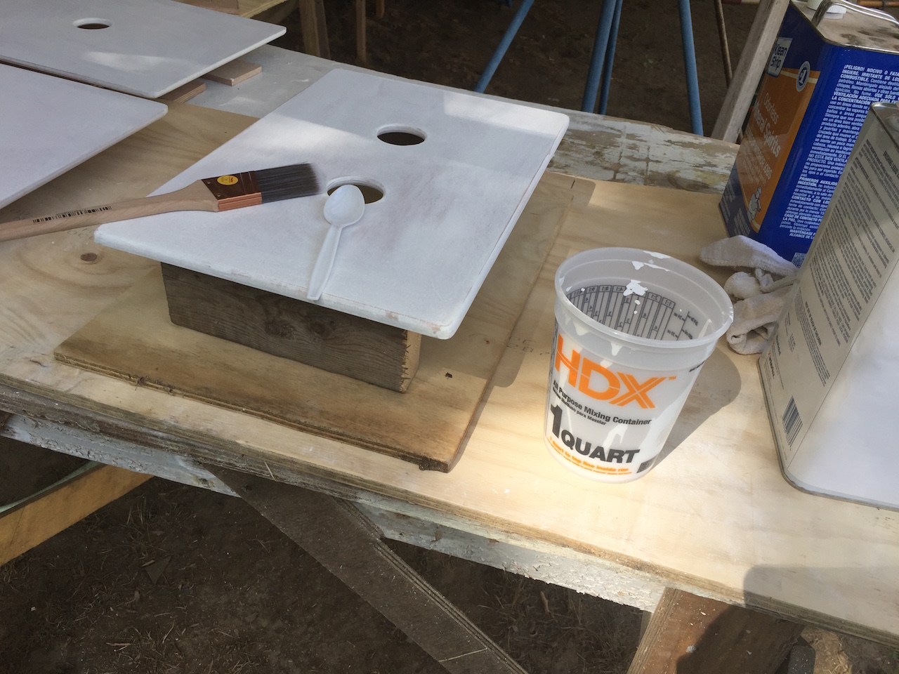
As usual, plenty of thickened epoxy fills the gaps and smoothes the corners. Note that the opening for the sink has been cut into the countertop.
The following photo shows where I’ve filled the countersunk screw heads in the forward-cabin side of the bulkhead.
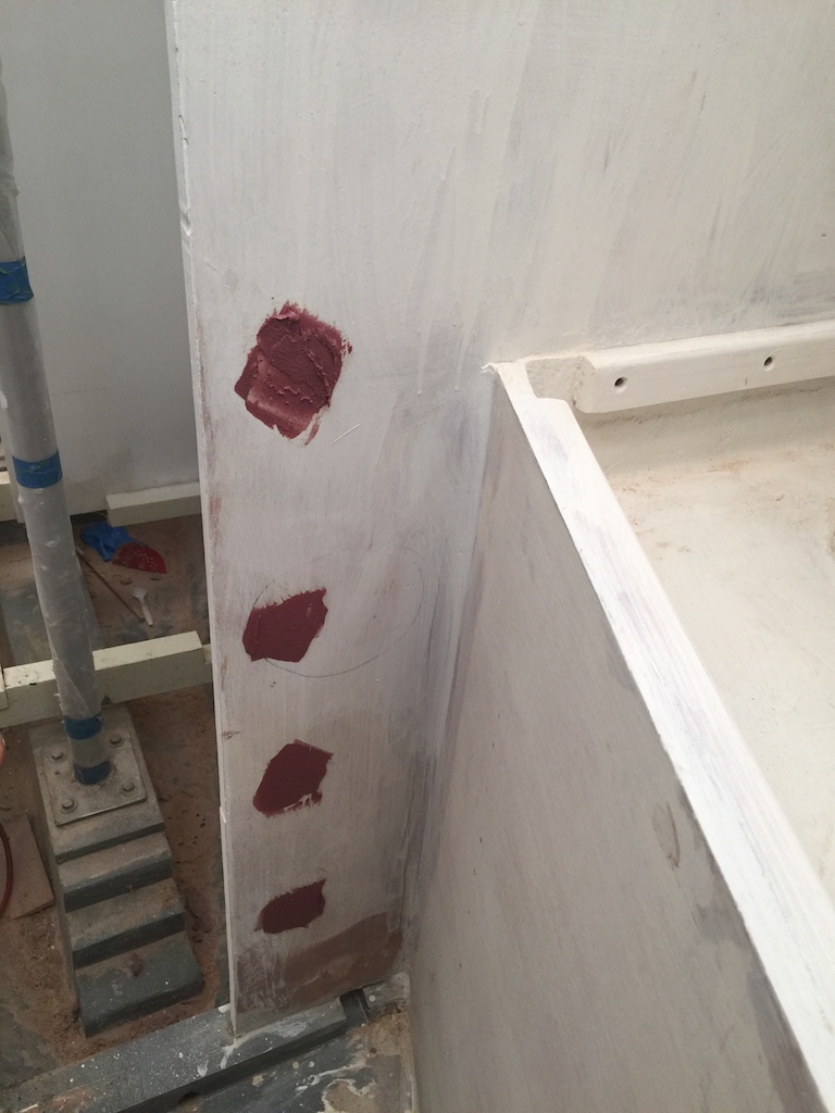
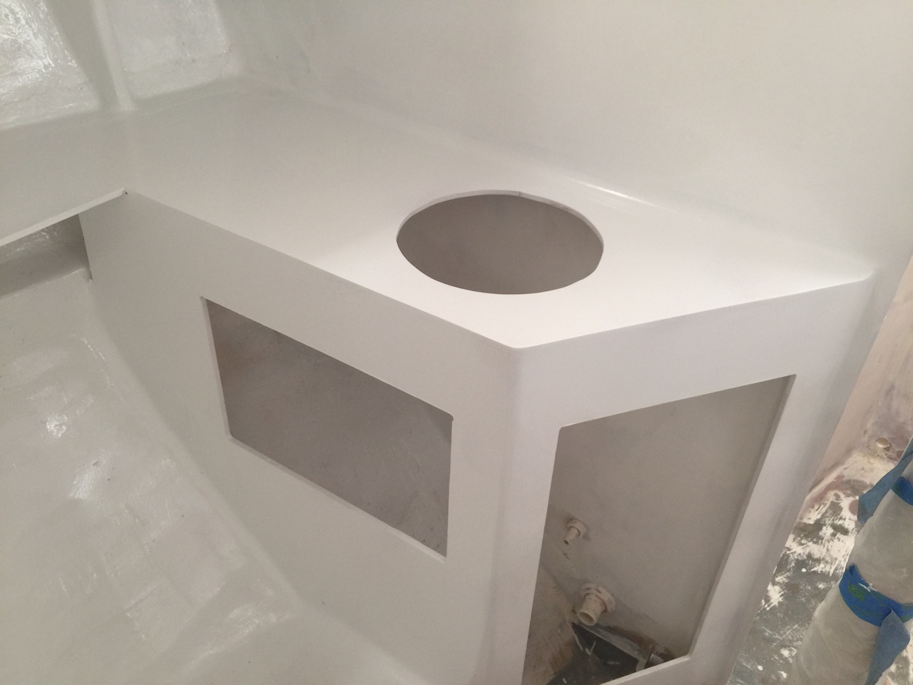
After some sanding, this area was ready for primer and paint.
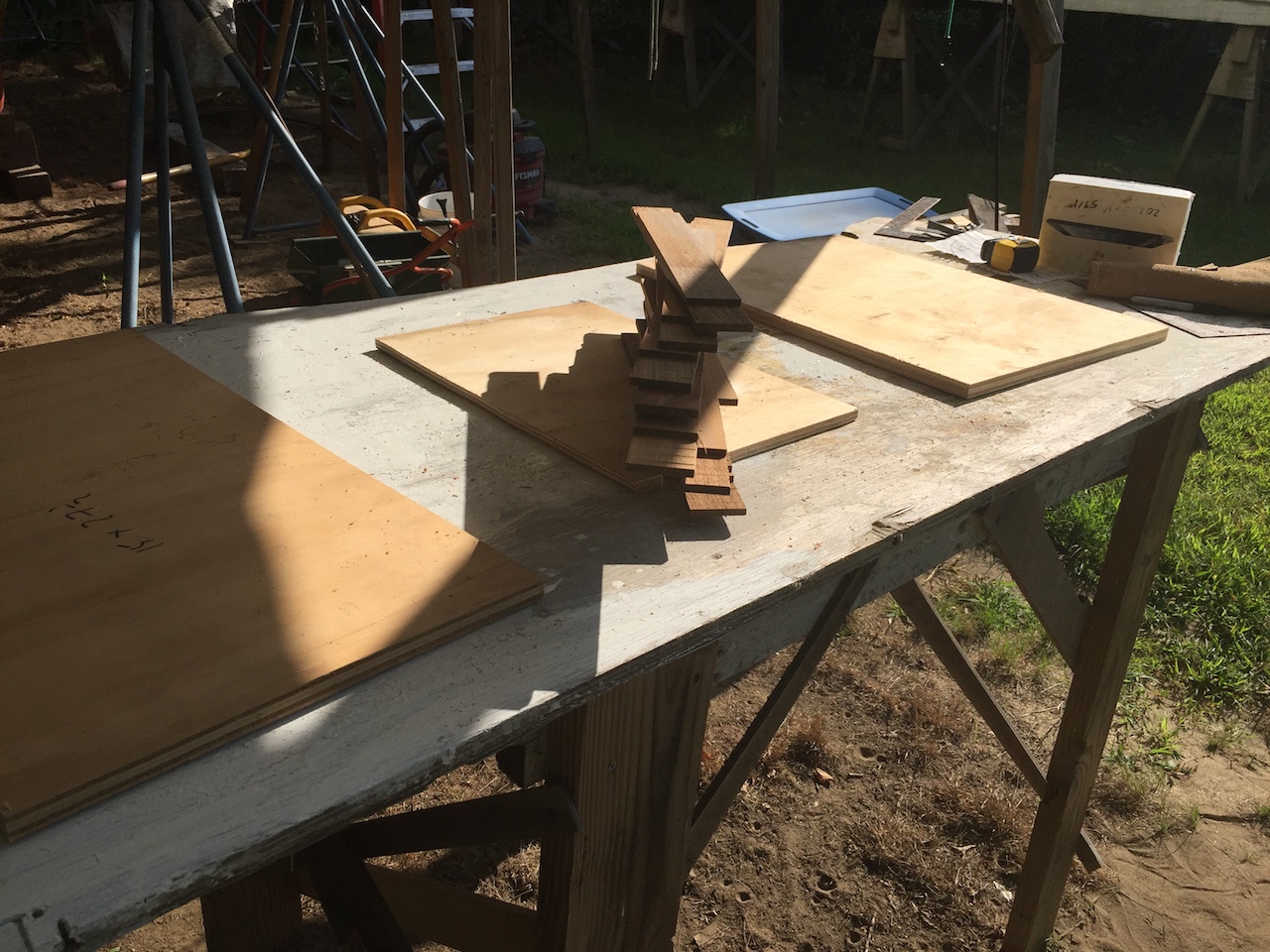
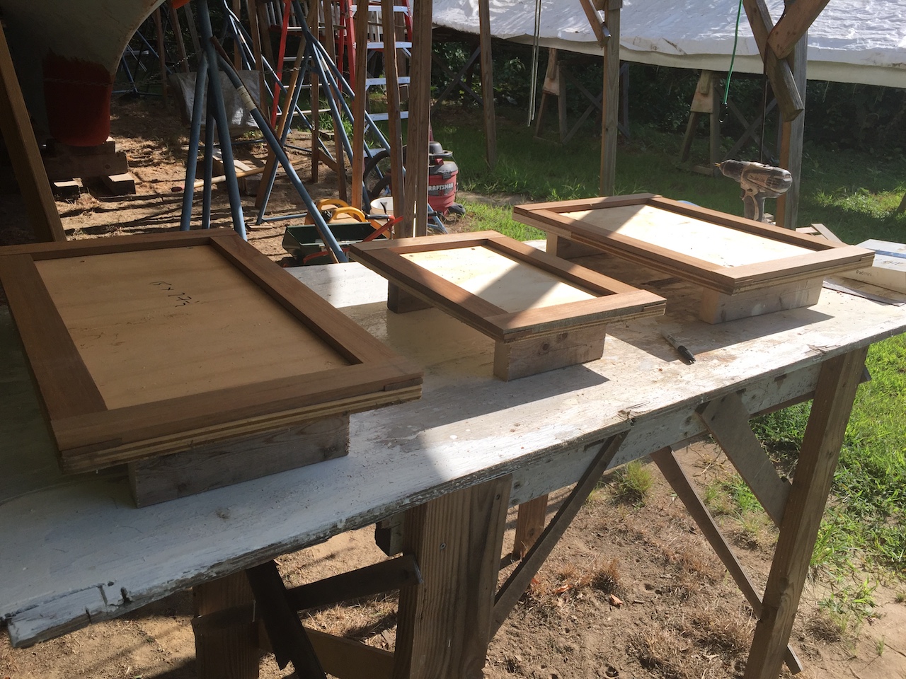
My next task was to make three doors–two for the two rectangular openings you see in the photo above, and another for the rectangular opening beneath the galley sink. I have some teak left over from the cabin-sides project, which I used for the trim. The photo below shows the three plywood panels and some teak laying across them. On the far end of the table is the trim for the ice-box lid, which was built more than a year ago.
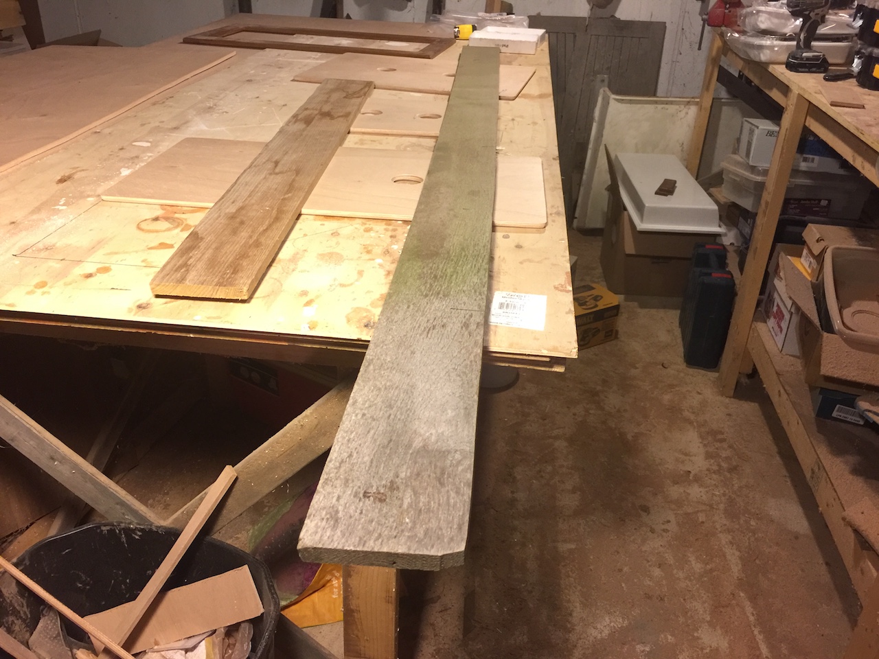
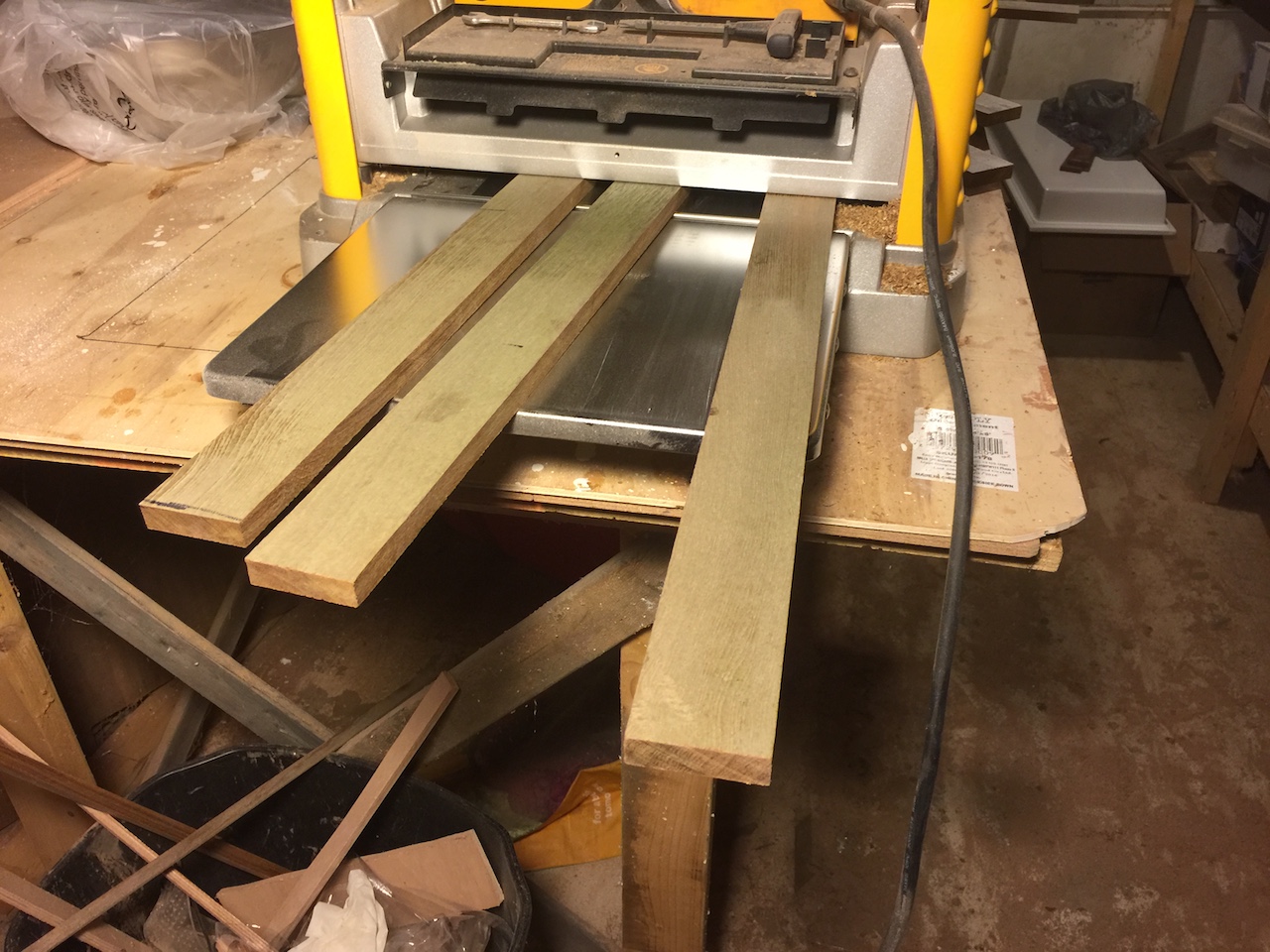
I ripped the board into 2″ widths, then used the planer to clean them up and give them equal thicknesses.
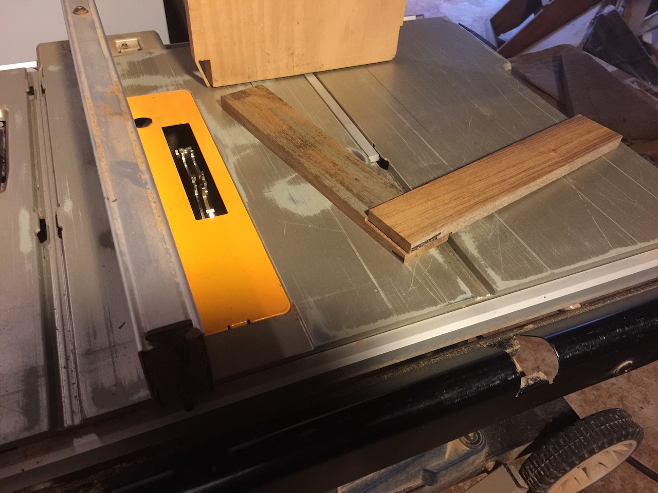
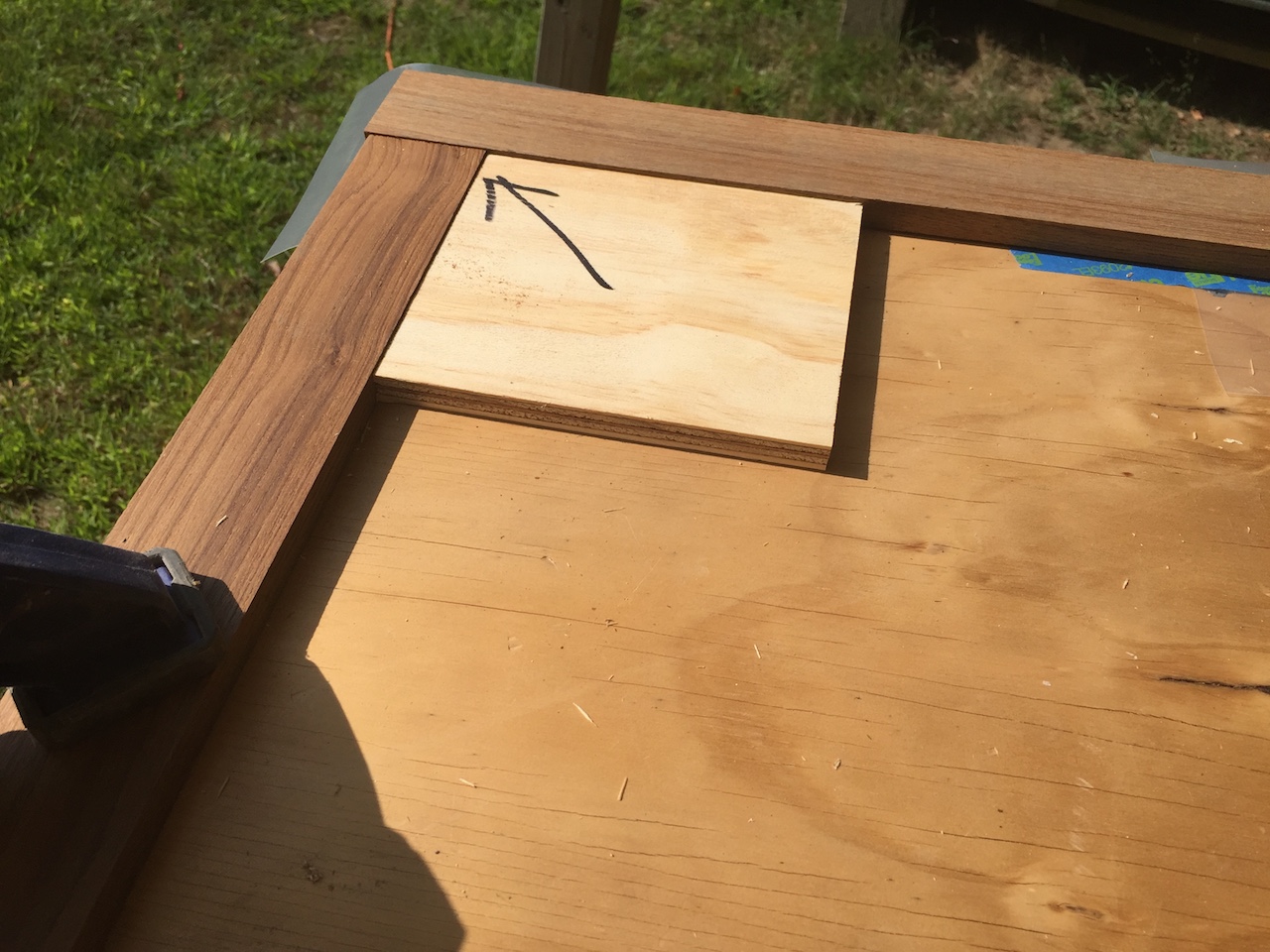
My procedure for making the lap joints was discussed previously in the context of the icebox-lid trim. I use the dado set to remove half of the thickness of the board, near the ends. Using some scrap, I gradually adjusted the table-saw fence location and the blade height to find the optimal setup. In the photo below, based on the test fit of the joint, we can see that the fence is too close to the blades and the blades are too low.
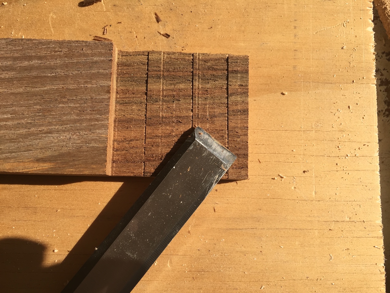
The dado set is a set of stackable saw blades, each with a wide kerf. Together they act as one very wide saw blade. It’s a great tool, but there’s still a little cleanup after making the cuts.
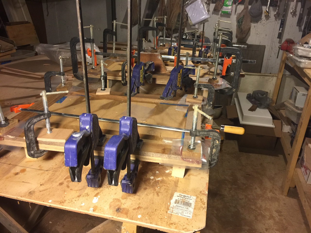
Gluing up the joints (with epoxy) requires plenty of clamping and careful squaring up of the pieces. I began this process by cutting some scrap plywood into pieces whose outside dimensions roughly match those of the rectangles of trim.
I began by clamping a long-side piece to the board, with the joint facing up. Next, I fit and squared up a shorter piece, with the joint facing down. I continued this all the way around until I was able to remove the two shorter pieces with confidence that the firmly clamped longer pieces were basically parallel and in the correct position to receive the shorter pieces.
The final clamp-up was done in the workshop.
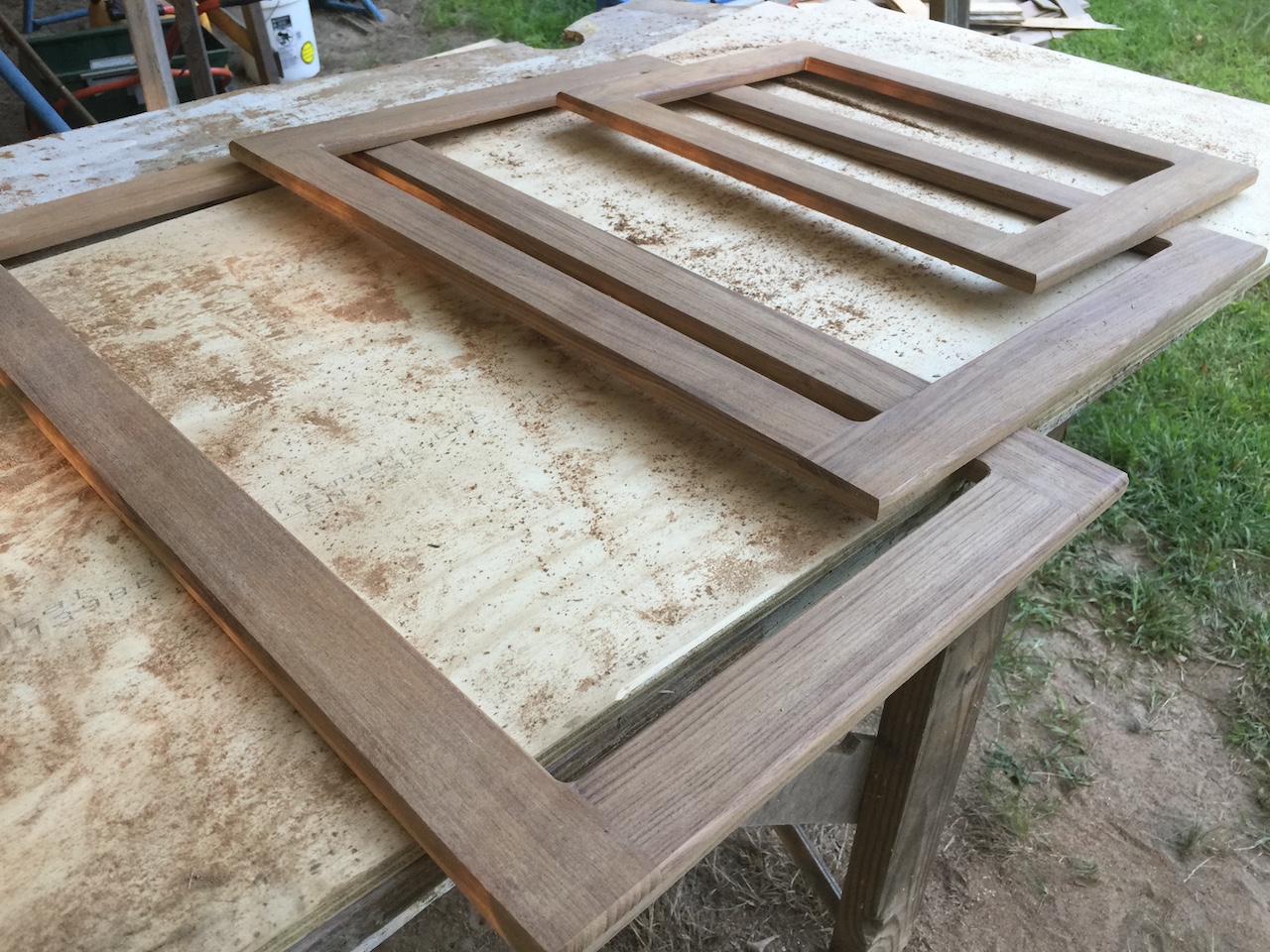
The following photo shows one of the pieces after removing the clamps.

After about an hour of sanding and few minutes using the trim router the pieces were ready for fine sanding, then a first coat of varnish.
I primed/painted the plywood pieces as I was varnishing the trim. To save time, I like to paint both sides of a piece at once (if possible) instead of having to wait for one side to dry before painting the other. For the plywood pieces, I rested one painted side on three upturned screws. (Basically, I drill drywall screws through small pieces of scrap plywood. The plywood keeps the screw pointed upward and I can place a painted side on these screws with the contact area being only three tiny screw points. The small imperfections caused by the screw heads contacting wet paint can be touched up later, but I kept these on the inside-side of the doors, where they will never be noticed.)
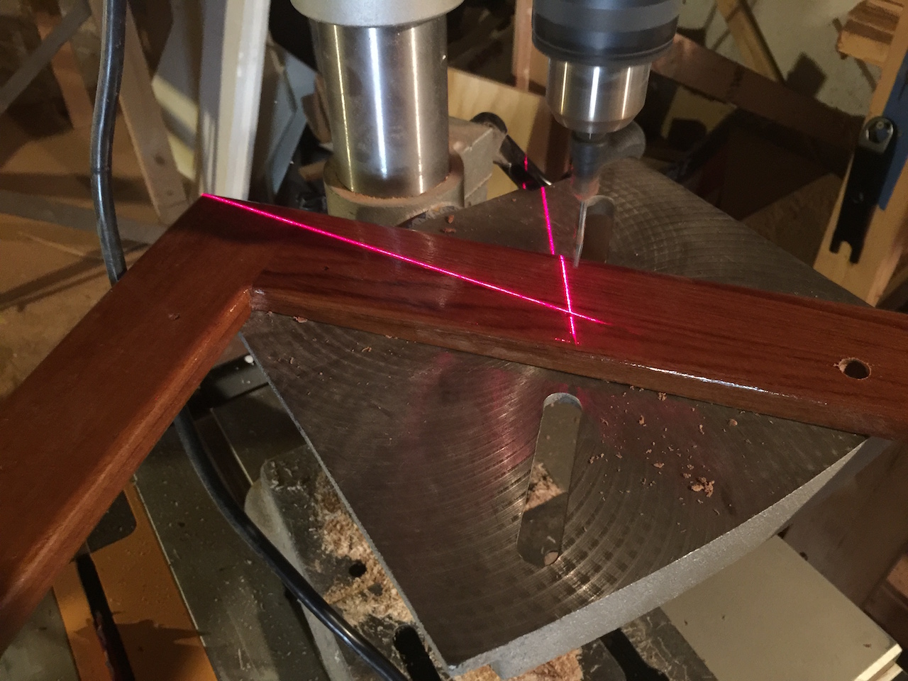
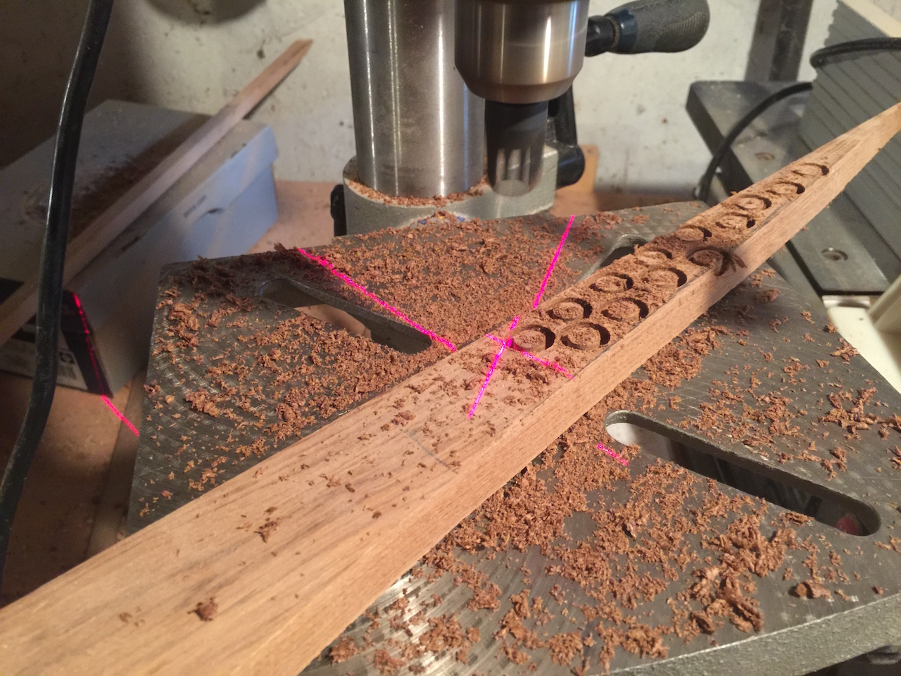
I use a similar technique for speeding up the varnishing of the trim. In this case, I drill three shallow holes on the backside of the trip and near the inside edge, so the holes will will be covered by the plywood panel eventually. I screw drywall screws into these holes, and you can see how this works in the photo below.
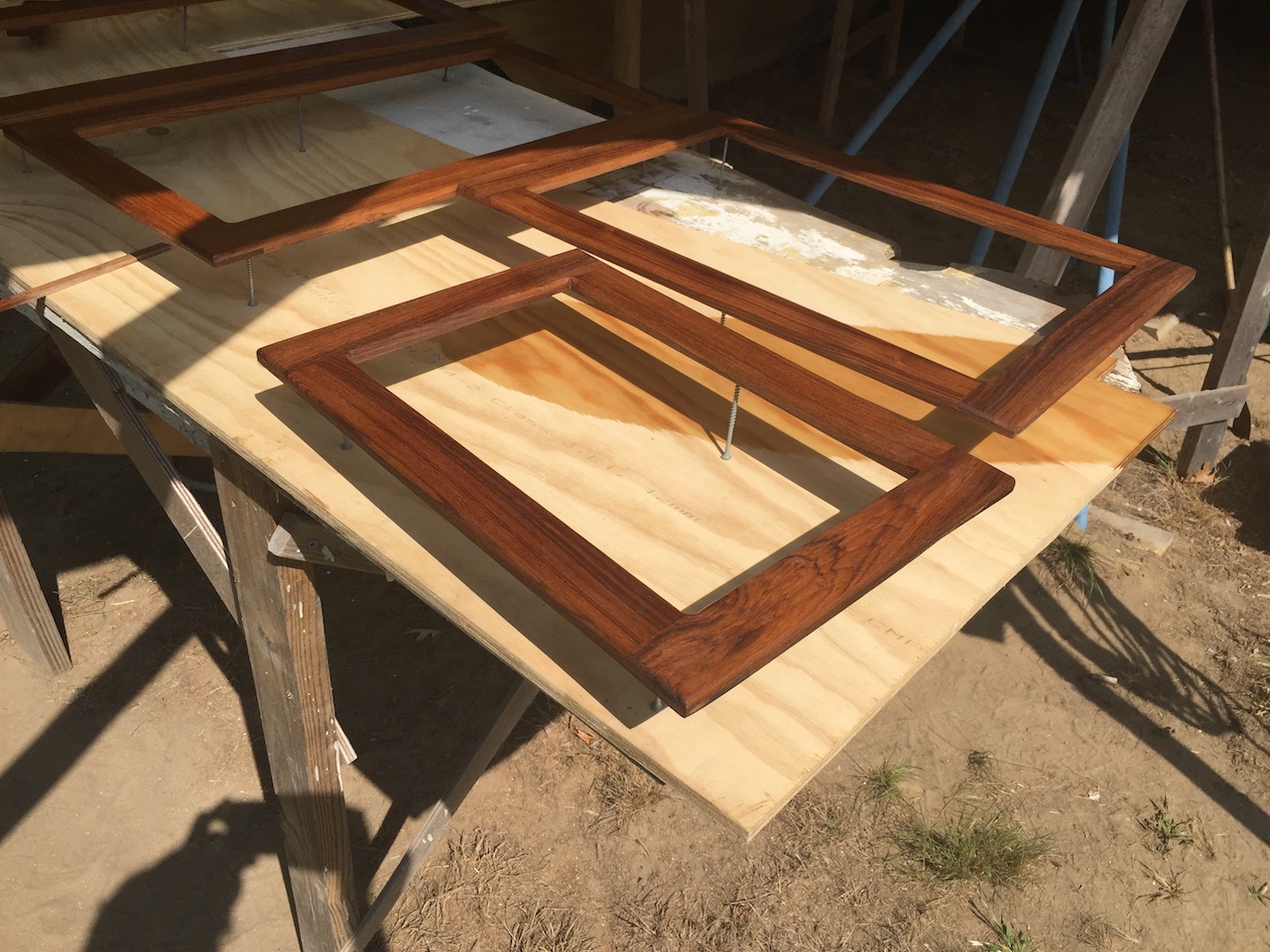
After three coats of varnish, I used small stainless screws to attach the trim to the panels.
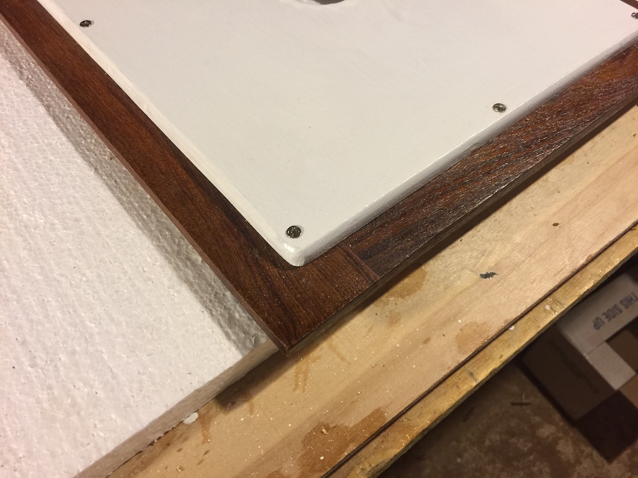
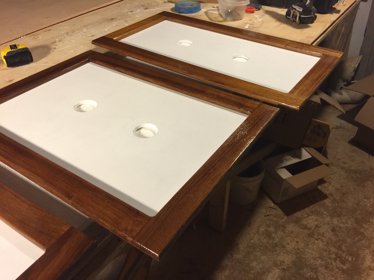
In the following two photos the doors are are only balanced in place. The small door in the head compartment will not be hinged because the toilet would interfere with its swing. Instead of hinges, I will probably use magnetic catches to hold it in place. The other doors will be hinged and have positive latches to keep them closed. For now, though, these doors have been moved off the boat until later.
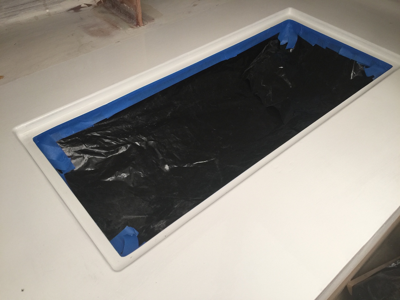
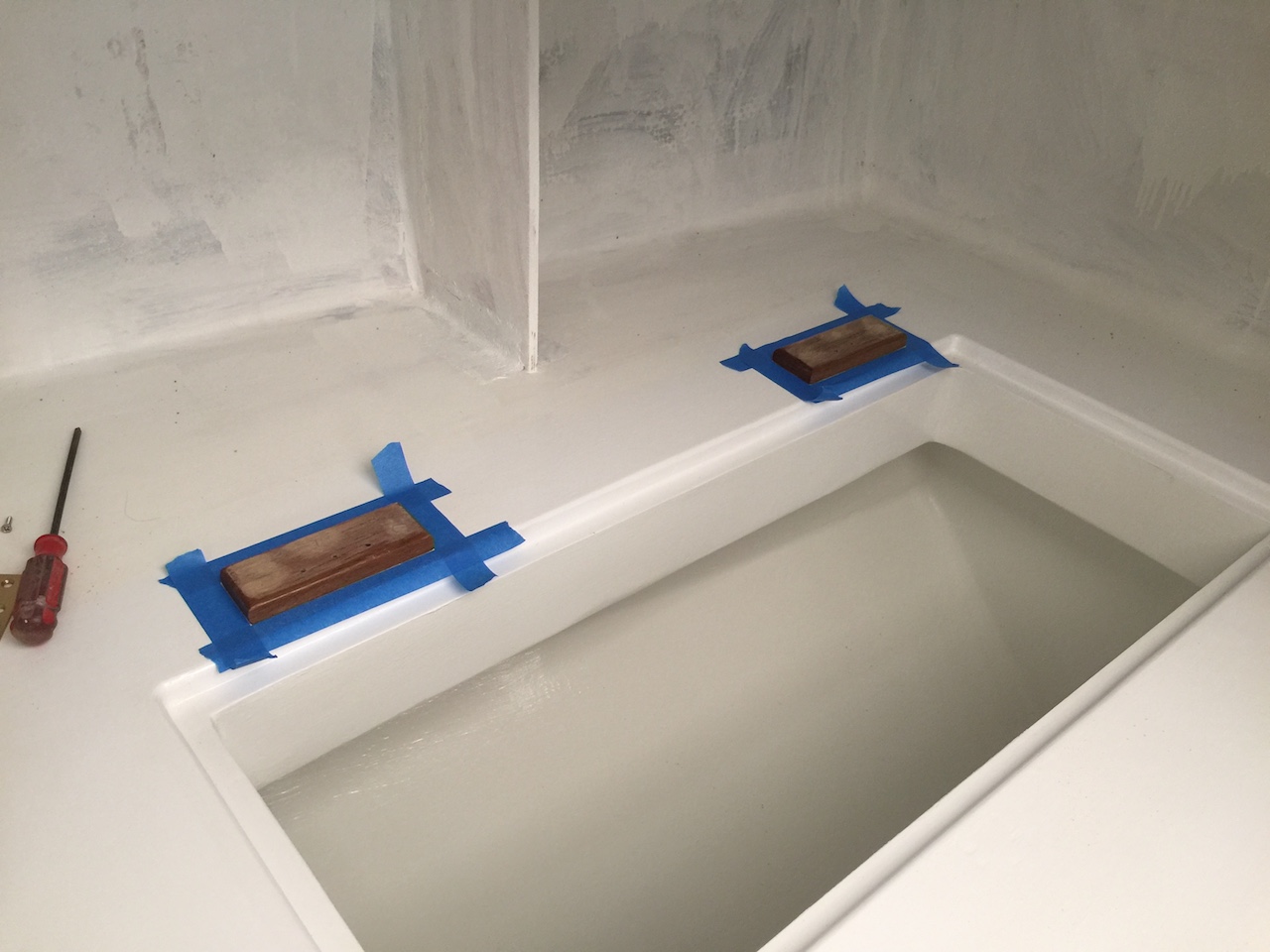
Meanwhile, back in the galley, I decided that I would restrict the two-part finish only to the inside of the icebox. In the photo below I have masked off the inside of the icebox and have applied the one-part finish to the surrounding area.
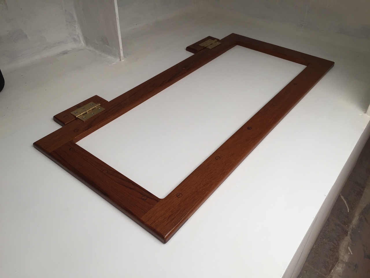
Next, I assembled and installed the ice-box lid. I began by drilling countersunk holes in the trim and hinge pads, then screwing the trim to the lid, and the hinge pads to the countertop.
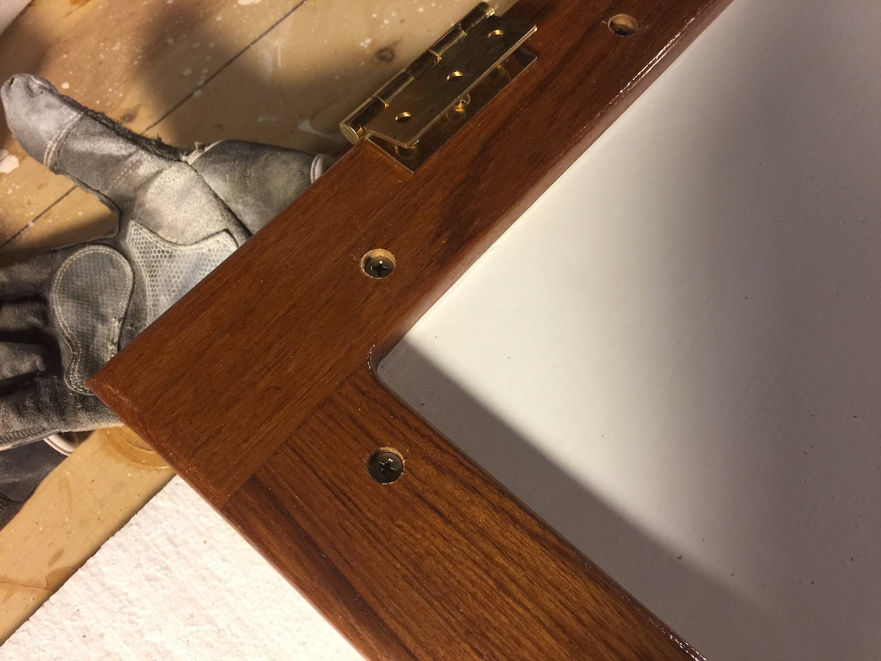
Next, I made the plugs from scrap teak.
After plugging the holes and varnishing, I performed the final installation.
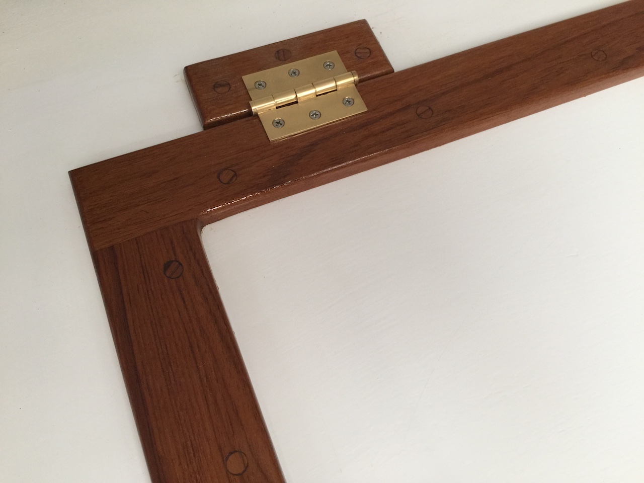
There are still a few issues that I need to address here.
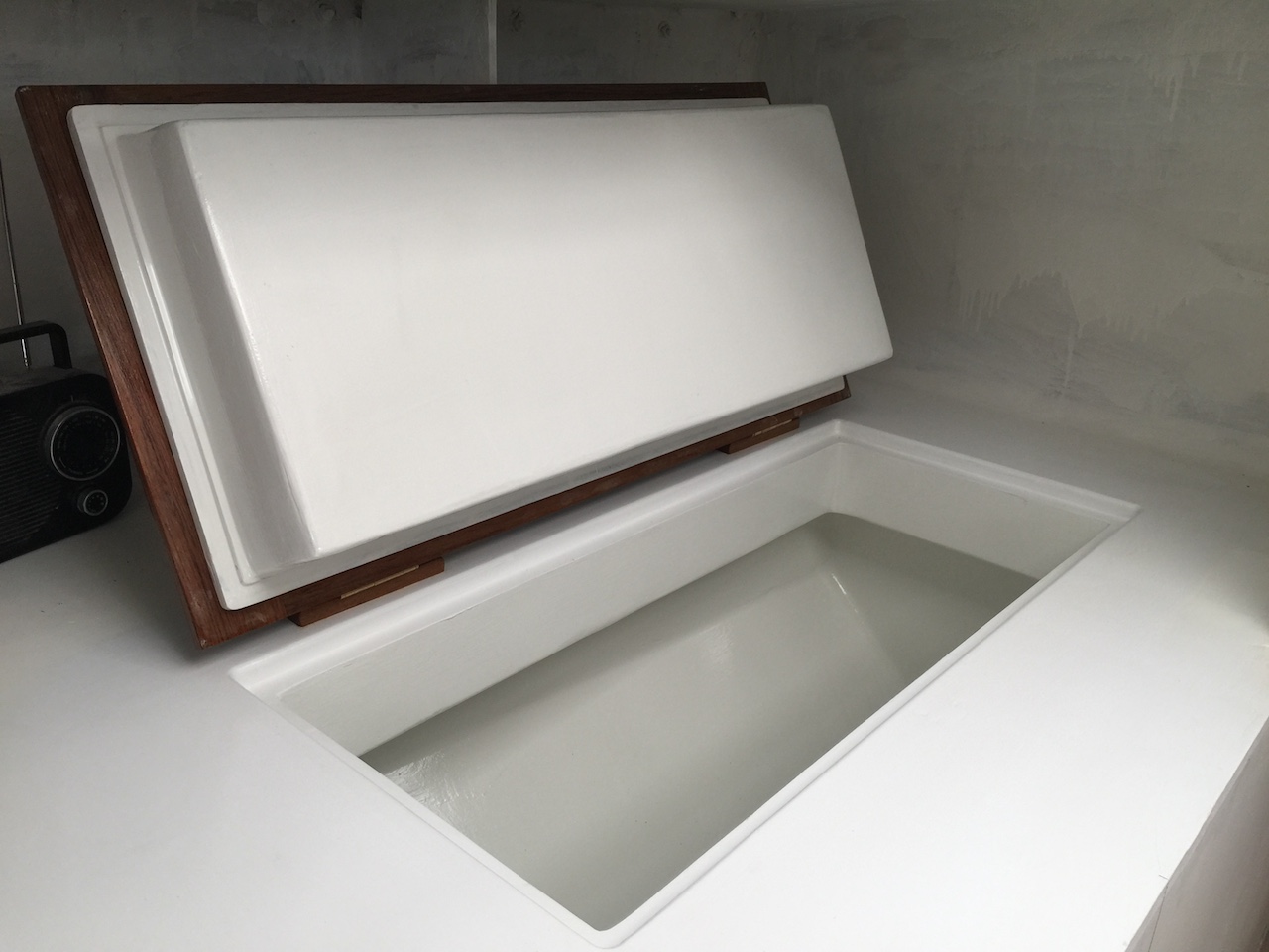
(1) I will probably install a thin gasket in the L-shaped grove in the countertop. Not only will this improve the insulation, but it will provide cushioning if the lid is dropped shut, thus protecting the teak trim from the sudden impact.
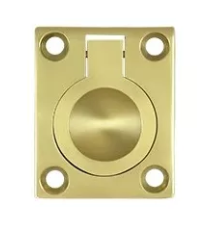
(2) A lid needs a handle. The traditional choice would be a flush ring-pull like the Deltana product shown in the image below.
The next steps involve the cabin sole, the water tanks, and the engine compartment enclosure.