10/24/17: Cabin Sole
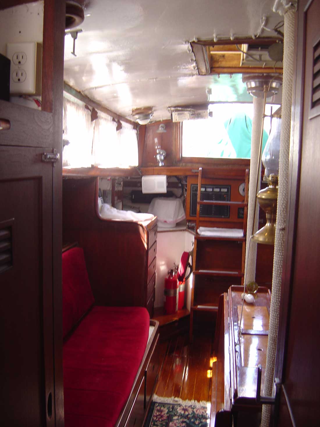
The original cabin sole consisted of about 25 teak boards (approximately 3/4″x8″ by various lengths, inlaid with strips of holly) all of which were screwed into floor beams, except a small panel over the bilge. You can see a glimpse of the original sole in the image below.
While a teak-and-holly sole is traditional, durable, and strong, its varnished surface can be slippery, so I’ve decided to go with a 3/4-inch plywood sole that I will paint and make non-skid. Besides, most of the original sole has been repurposed (dorade boxes, coasters, cleats, trim, etc.), and the original planks would have had to be modified to fit the changed floor plan.
To begin, I bored a 2-inch hole in some scrap wood and tested the fit around one of the three compression posts.
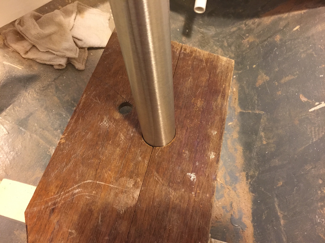
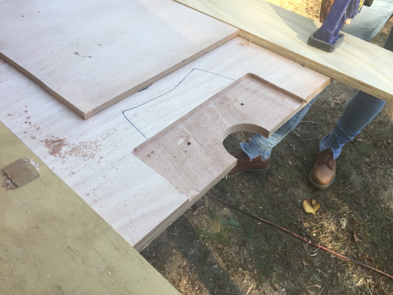
It was a good fit, but eventually I went with a 2 3/8-inch hole. Below is the beginnings of the template I used for the sole in the head area. My plan was two panels with a fore-and-aft seam that captures the compression post.
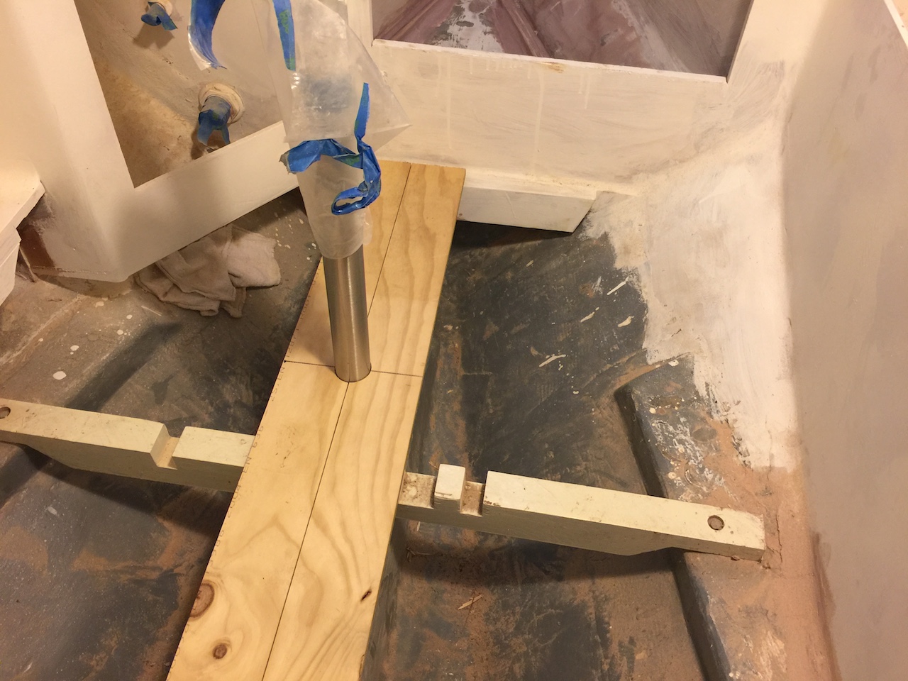
With the hot-glue gun and thin strips of 1/8-inch plywood, I finished the template in the usual way.
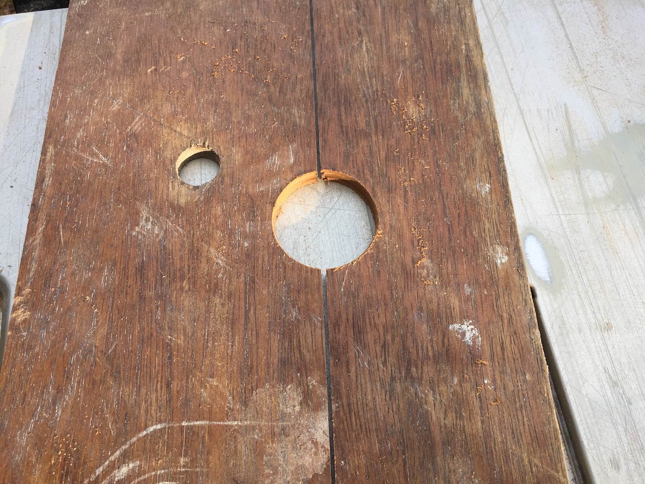
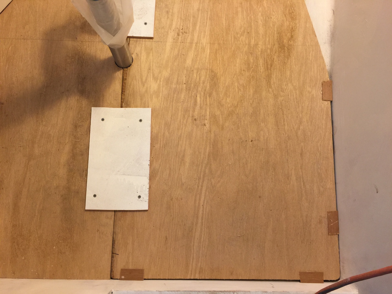
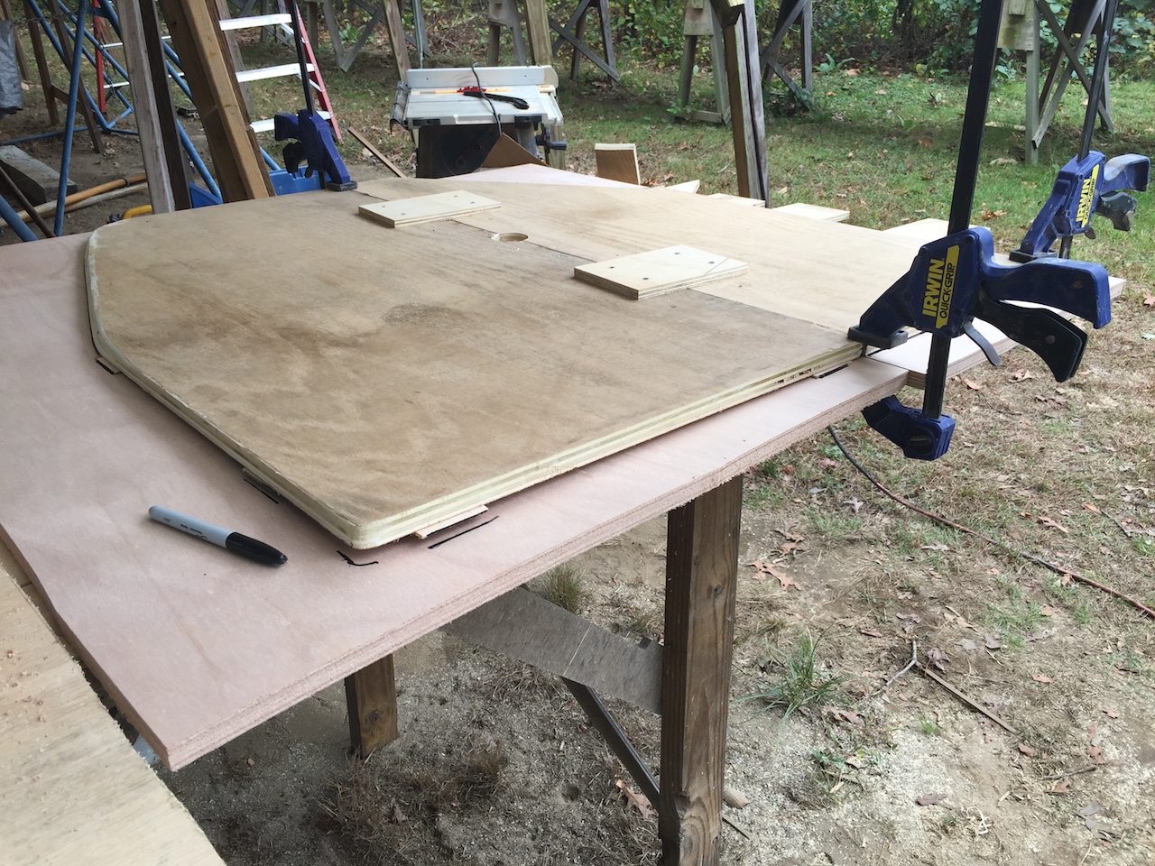
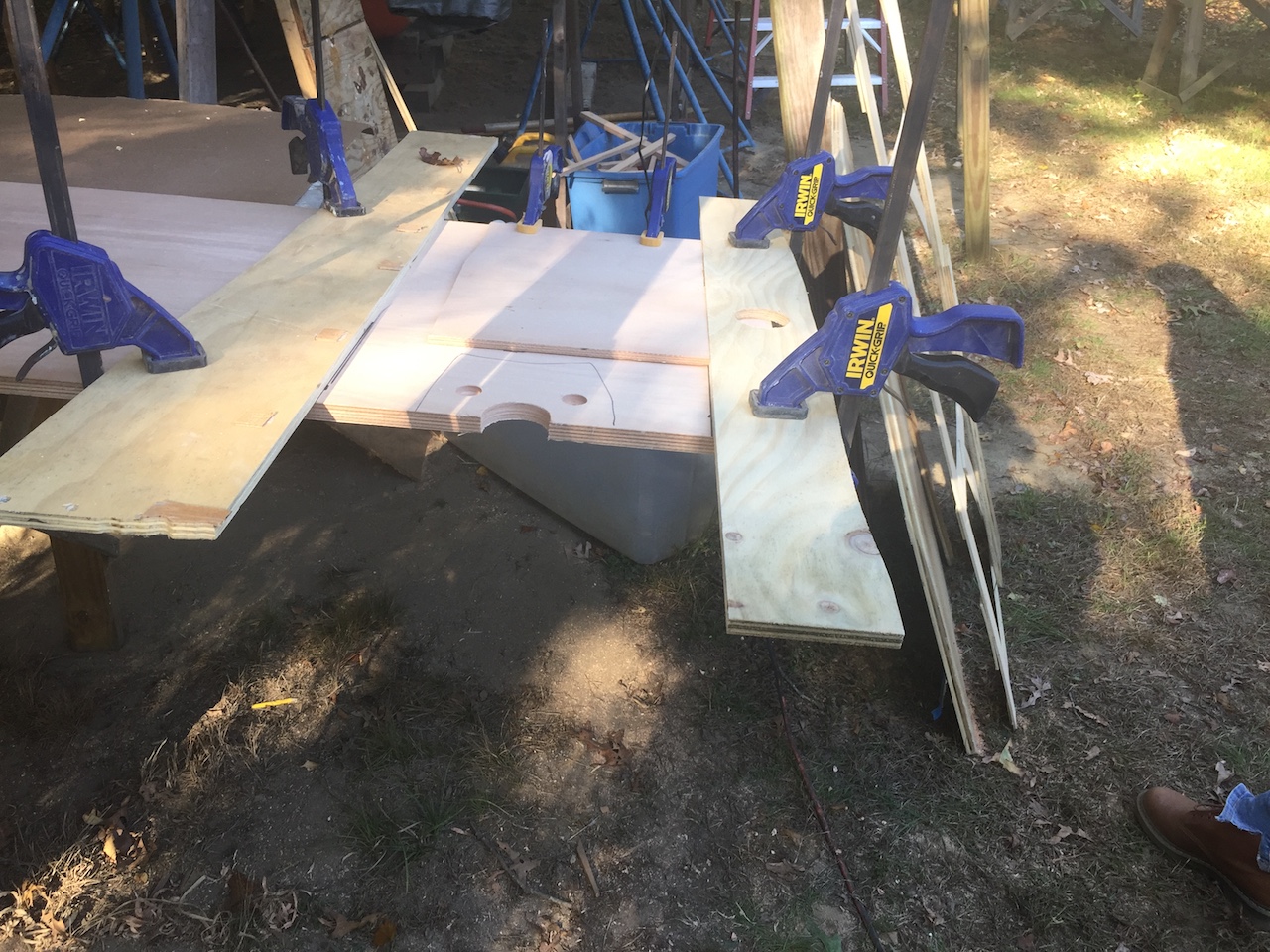
I decided to do a full test on some cheaper 3/4-inch plywood. Here is the template resting on the plywood. The trick here is to cut the plywood in two pieces, then flip them so that the two factory-cut make the centerline seam. With the seam held together tightly (by whatever means available) I then joined the two sides of the template, and then aligned the seam in the template with the seam in the panels. Next, I traced the outside edge of the template then drilled the hole with a hole saw. (Most of this work is not shown in the photos here.)
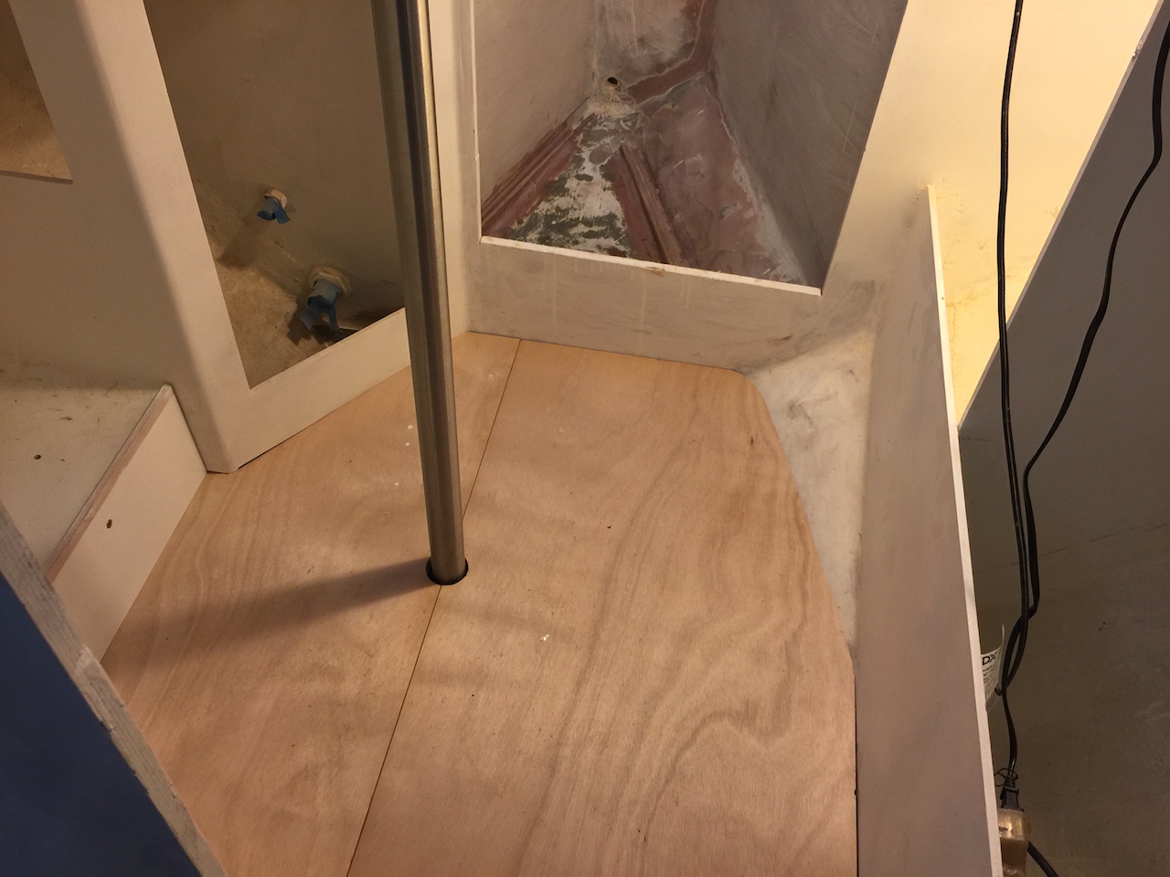
Here are the test panels in place.
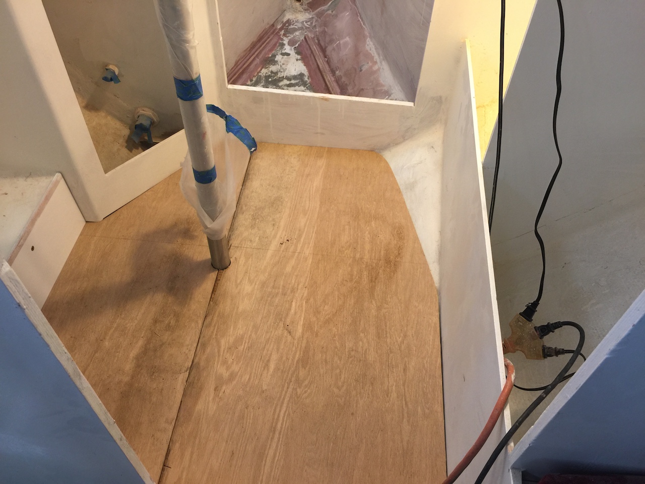
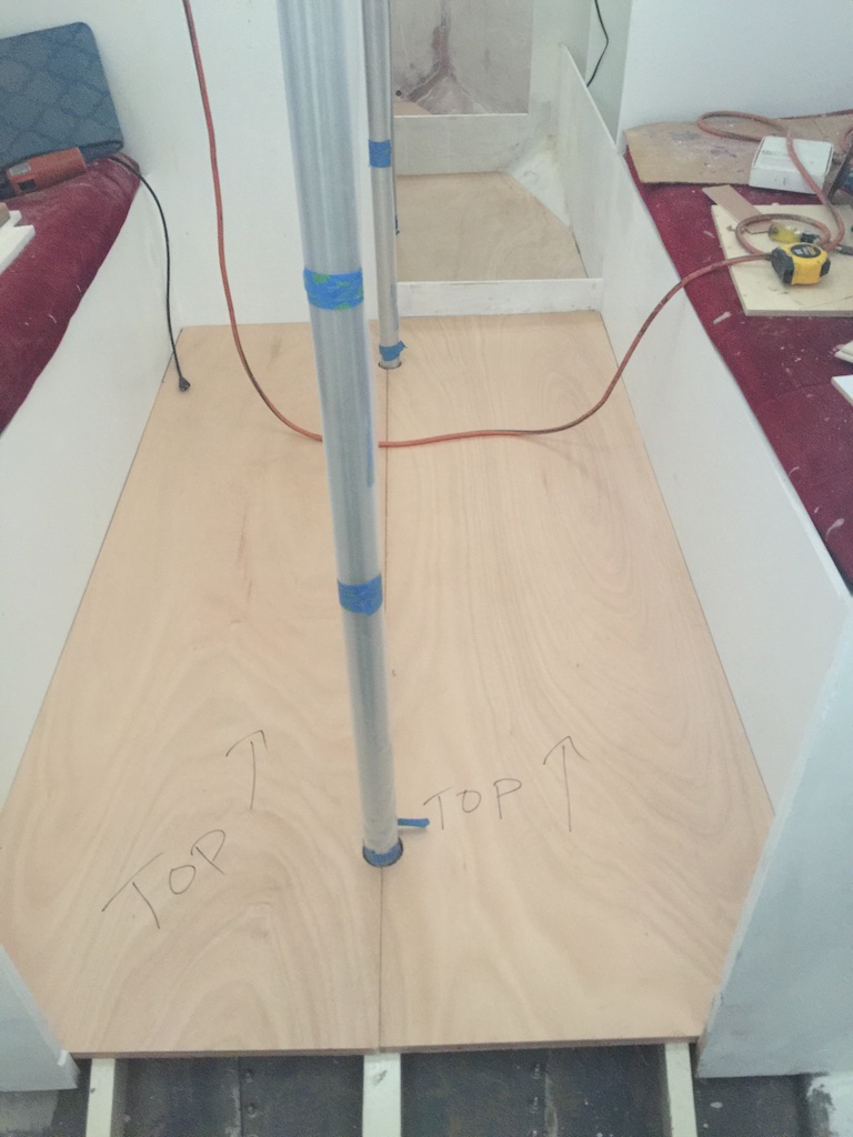
It was a pretty good fit, but I made some minor adjustments and then used these panels as a template for the final panels.
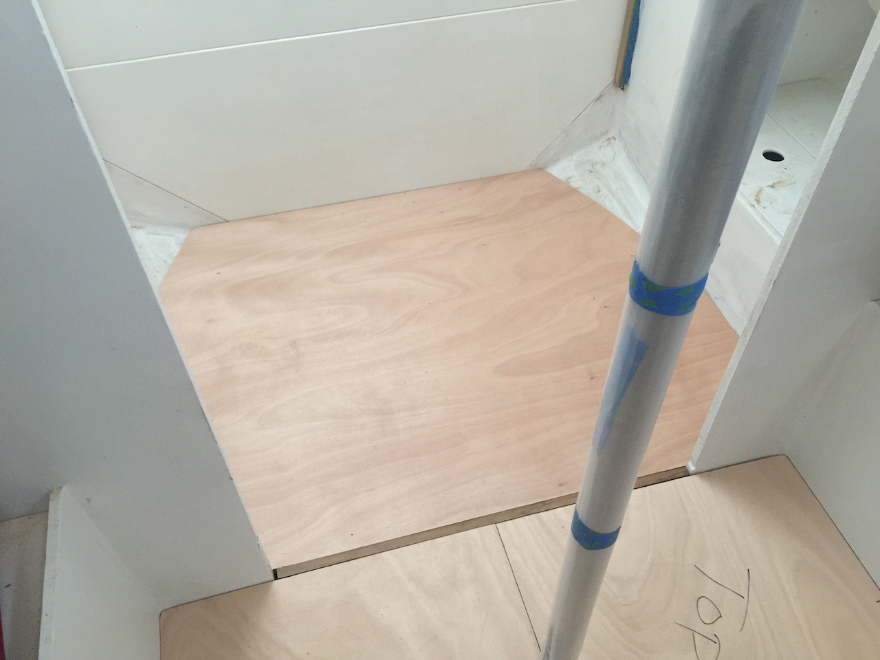
The photo below shows the final fit. The tricky part here was the starboard panel with its curved, beveled edge where the hull slopes upward into the head compartment. Knowing where to trim is difficult when you can’t see where the bottom of the panel is touching the beams and hull.
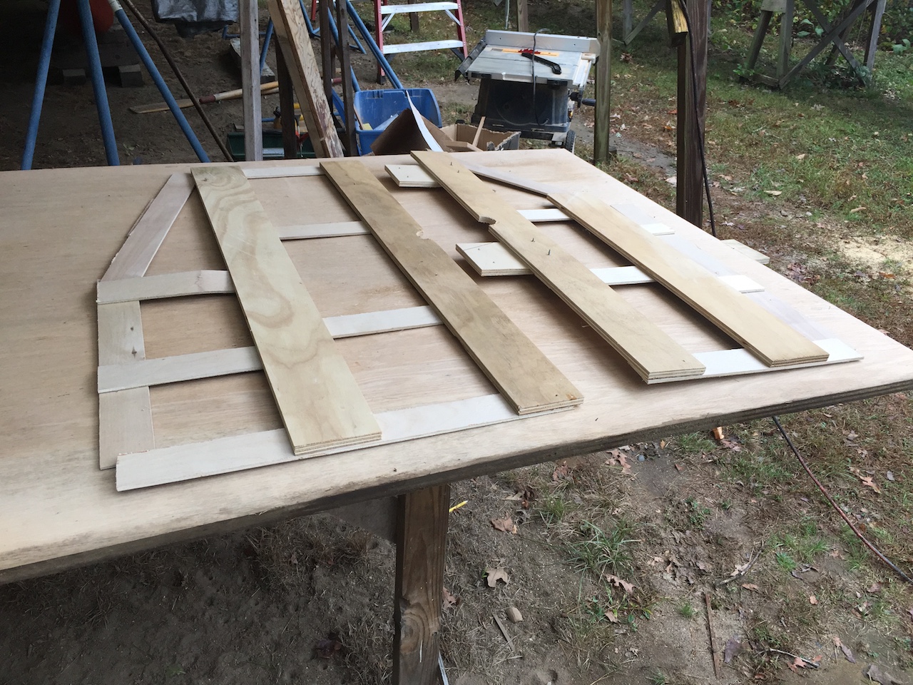
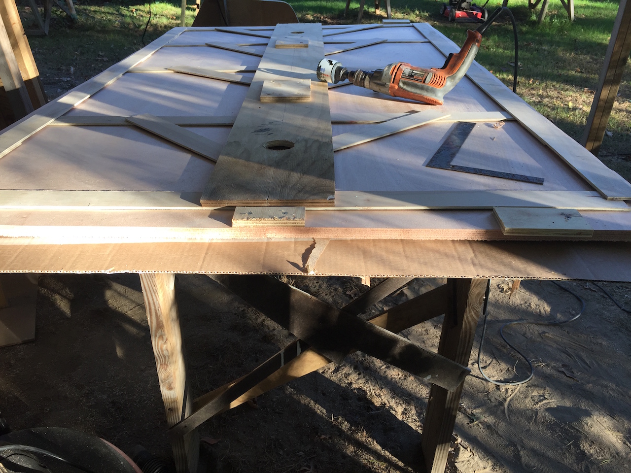
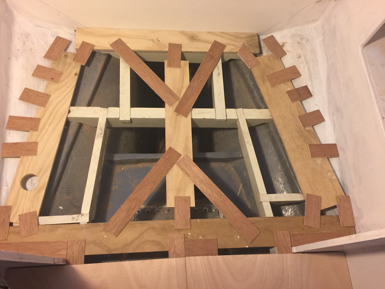
Moving aft, the photo below shows the symmetrical template for the two panels in the main cabin. This template, while much larger than the one above, was much easier due to the simple shape and not having to deal with the curvature of the hull.

This template is smaller than a 4×8 sheet of plywood, so I was able to get both panels out of a single sheet, with some useful scrap left over.
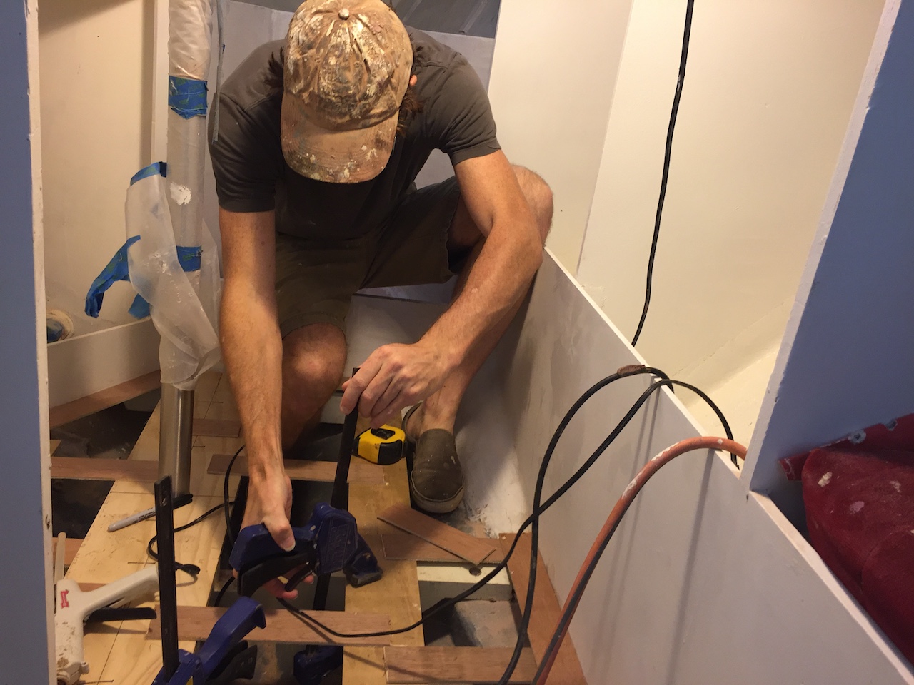
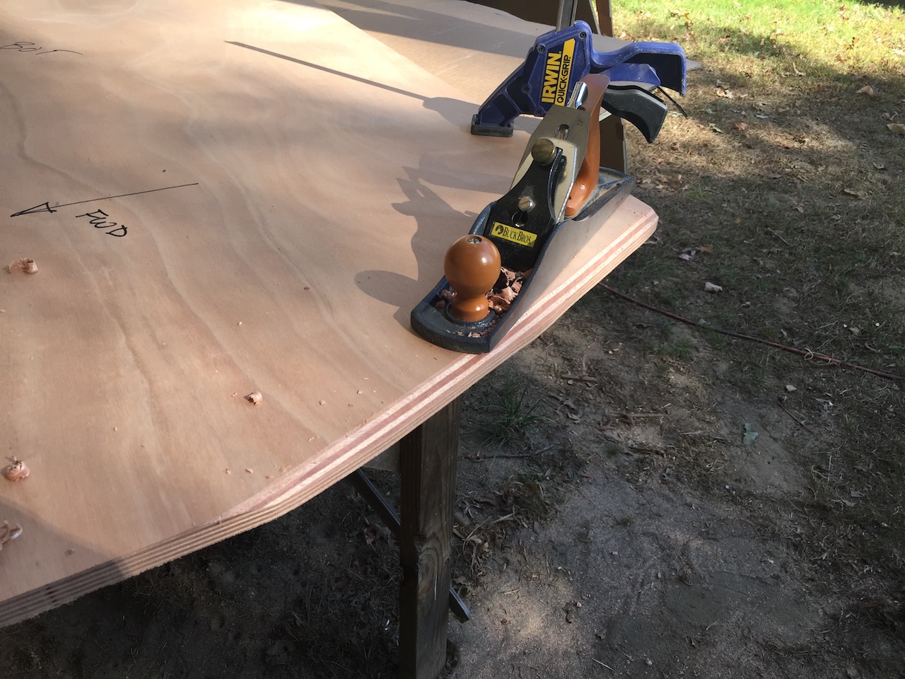
The jigsaw was used to cut close to the traced lines defining the outside perimeters of the panels, then the router and straight edge cleaned up the roughness.
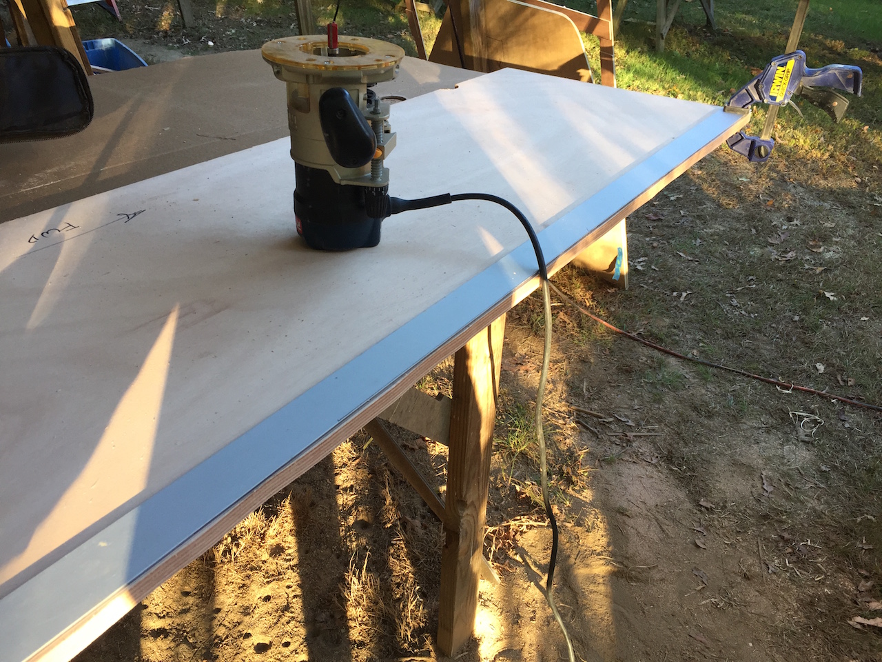
The bottom plates of the compression posts, and their bolts, in the main cabin, protrude slightly above the floor beams, so used the router to recess around the holes for the posts.
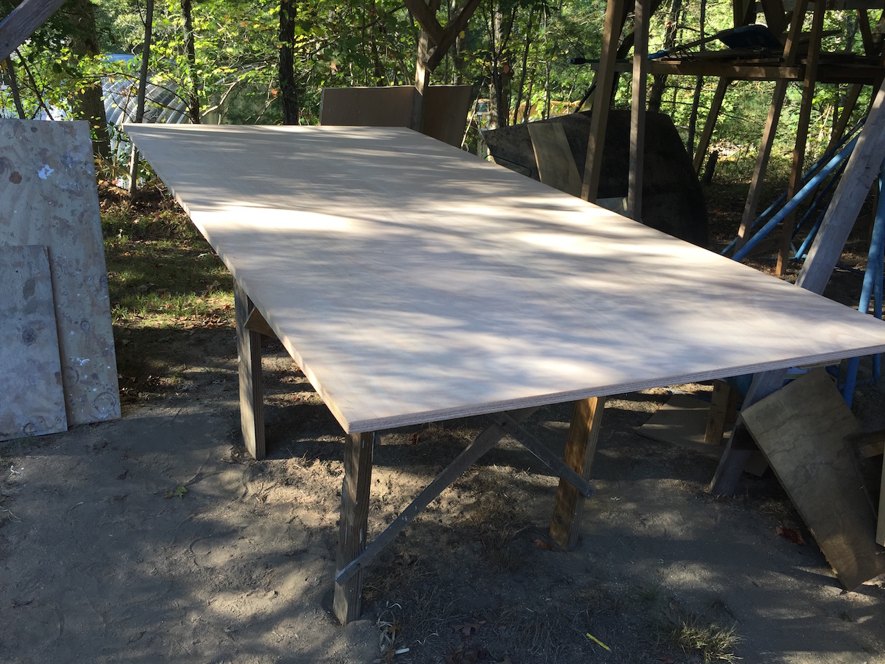
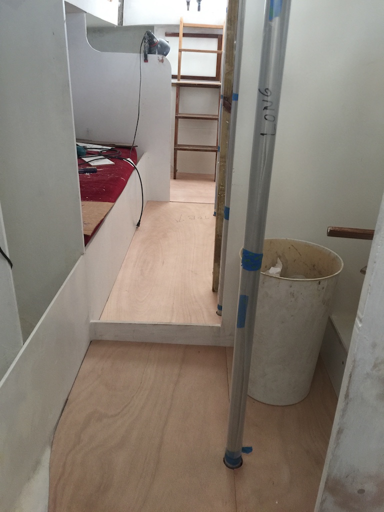
Here are the two large panels in place.
The photo below is the template for the panel for the galley sole.
I cut out the panel, then beveled the edges that meet the hull.
The narrow teak strip that fills the gap between the salon panels and the galley panel was repurposed from the original sole.
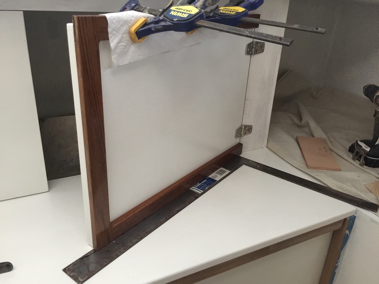
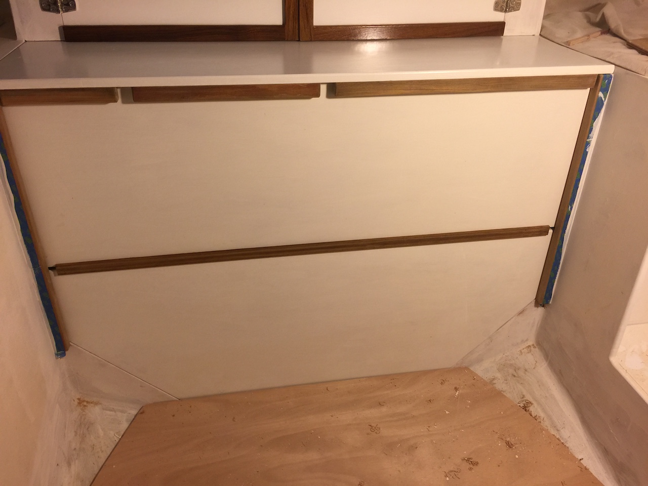
Meanwhile, I sanded the trim for the trim for the engine-compartment doors.
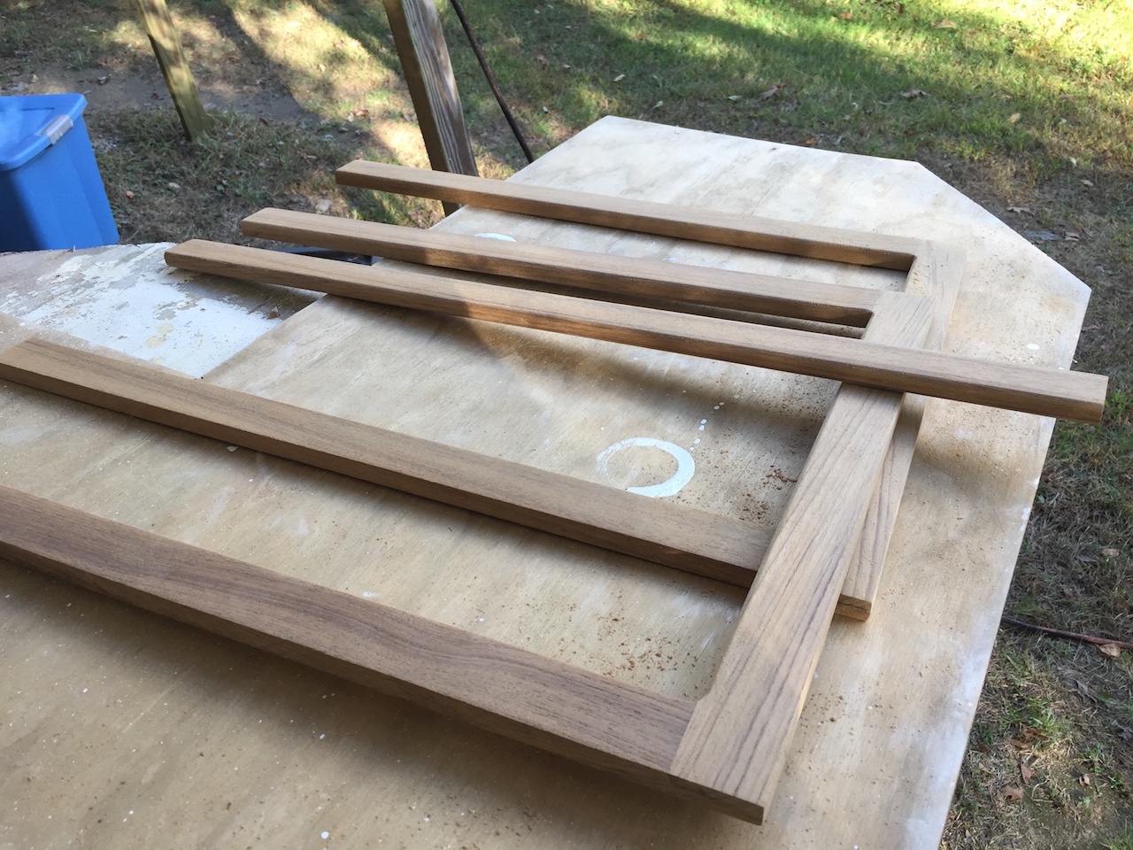
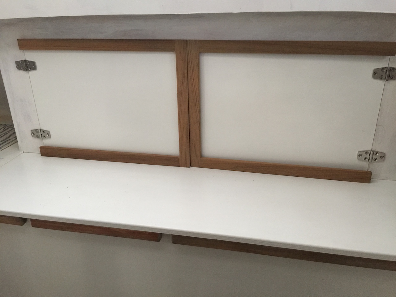
They were tested for fit, and later given three coats of varnish.
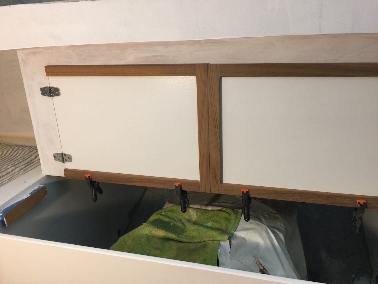
Final installation consisted of fastening the trim with screws (from the backside of the door). The angle square is being used to set the level of the bottom of the trim slightly above the shelf.
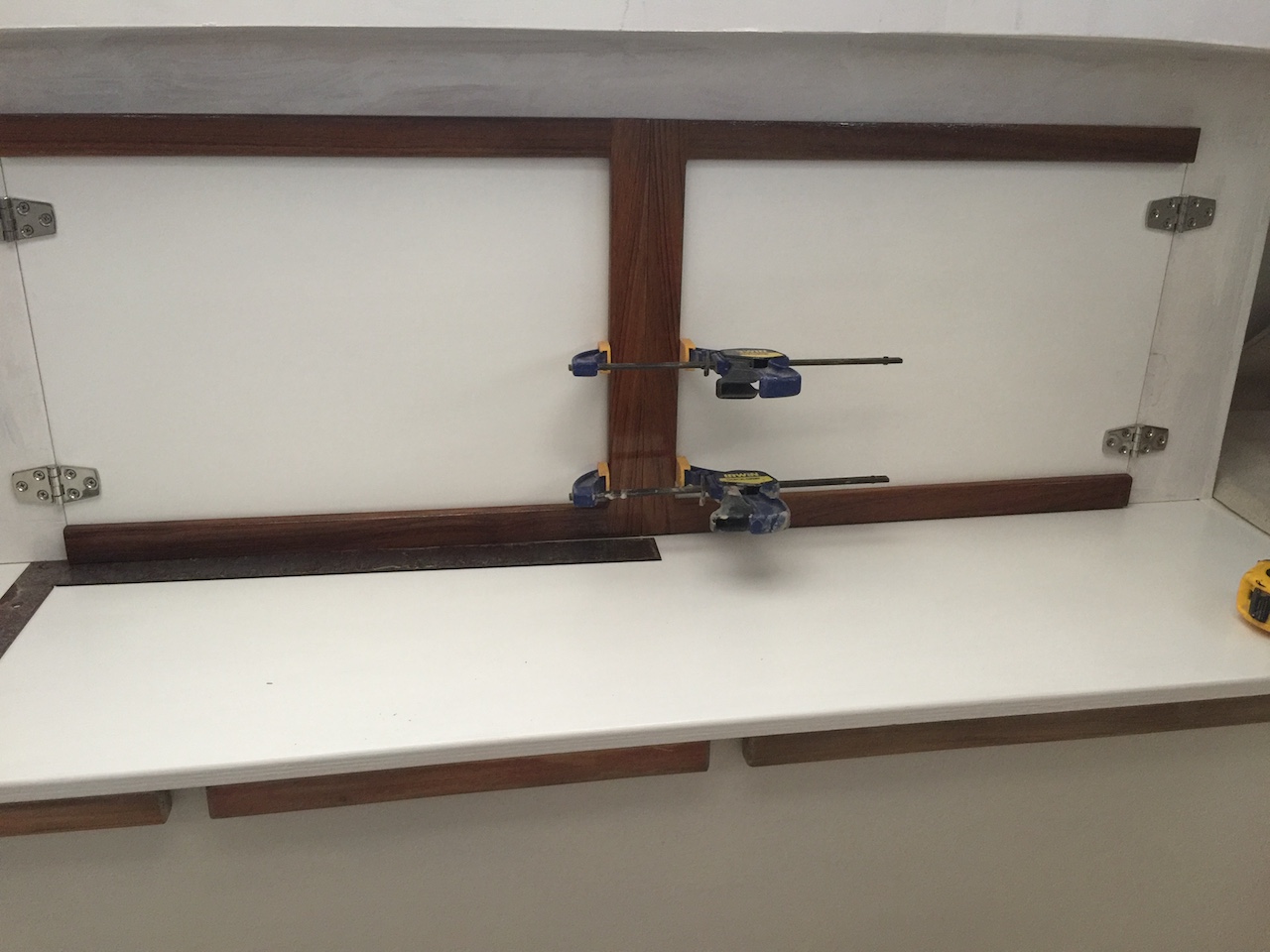
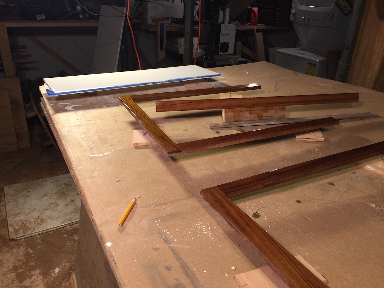
As we have seen, the shelf is supported by cleats on either end and by the drop-boards in between. The highest level of the drop-boards, however, was about 1/4 inch below the bottom level of the shelf, so there was some unwanted flex in the shelf. To bring the level of the top of the drop-board up, I added some teak trim where the two boards meet. The following photo shows a few test pieces.
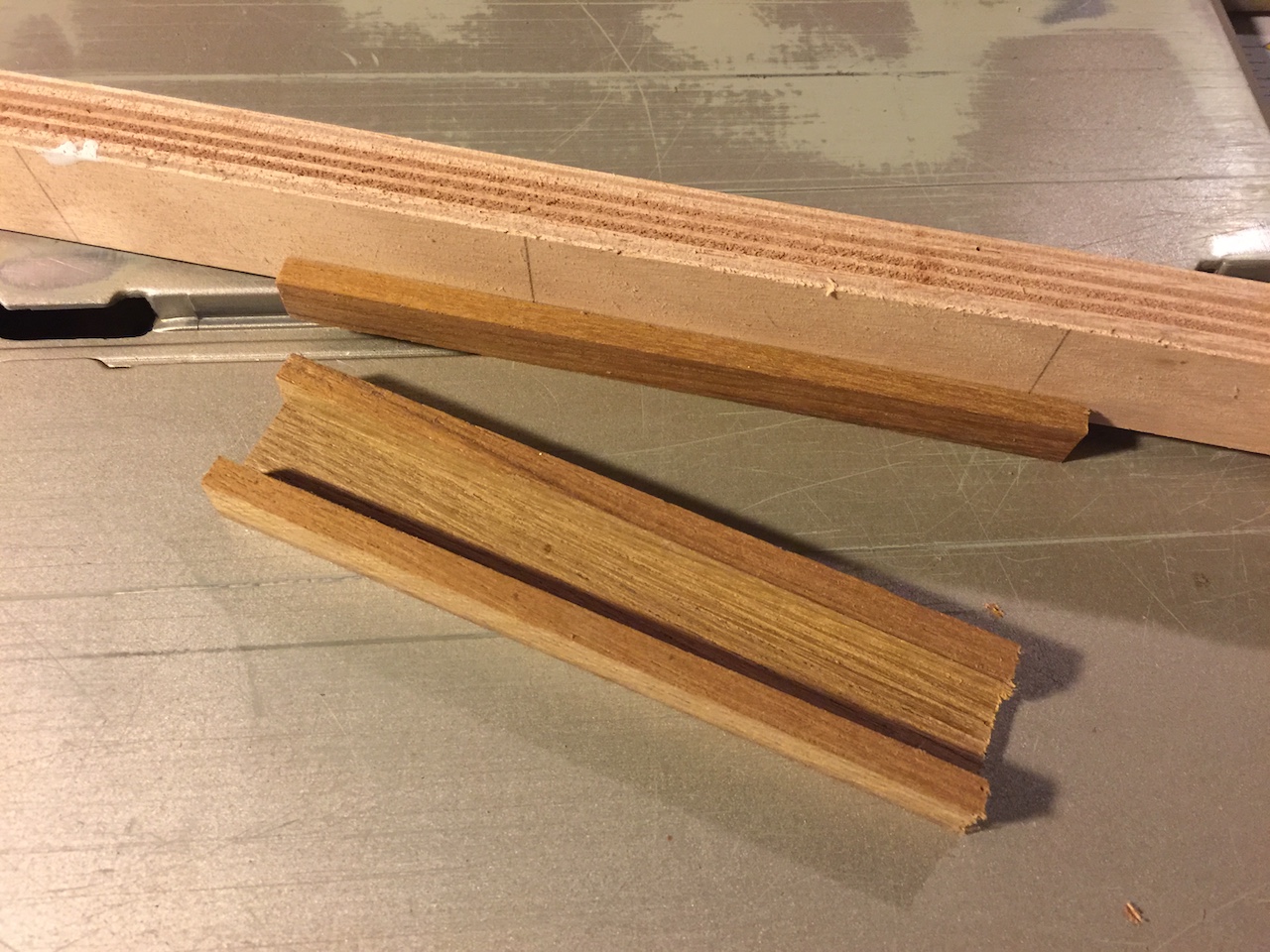
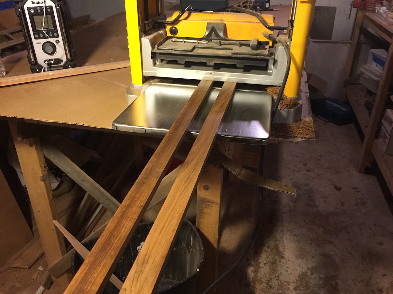
I milled up the full-length pieces, then installed with thickened epoxy.
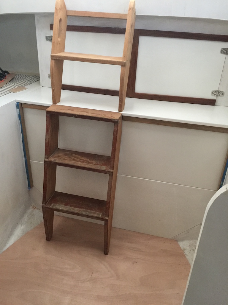
There’s still plenty of work to do here, and work will continue with details related to the companionway ladder.