6/23/18: Cap Rails
Next up in the cap-rail job was using the thickness planer to take the boards down to the desired height.
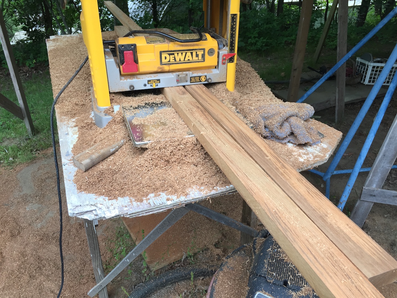
It turns out that some of my 5/4 stock was closer to 6/4, and here you can see where the planer has removed material from some of the boards, while not not even touching the others.

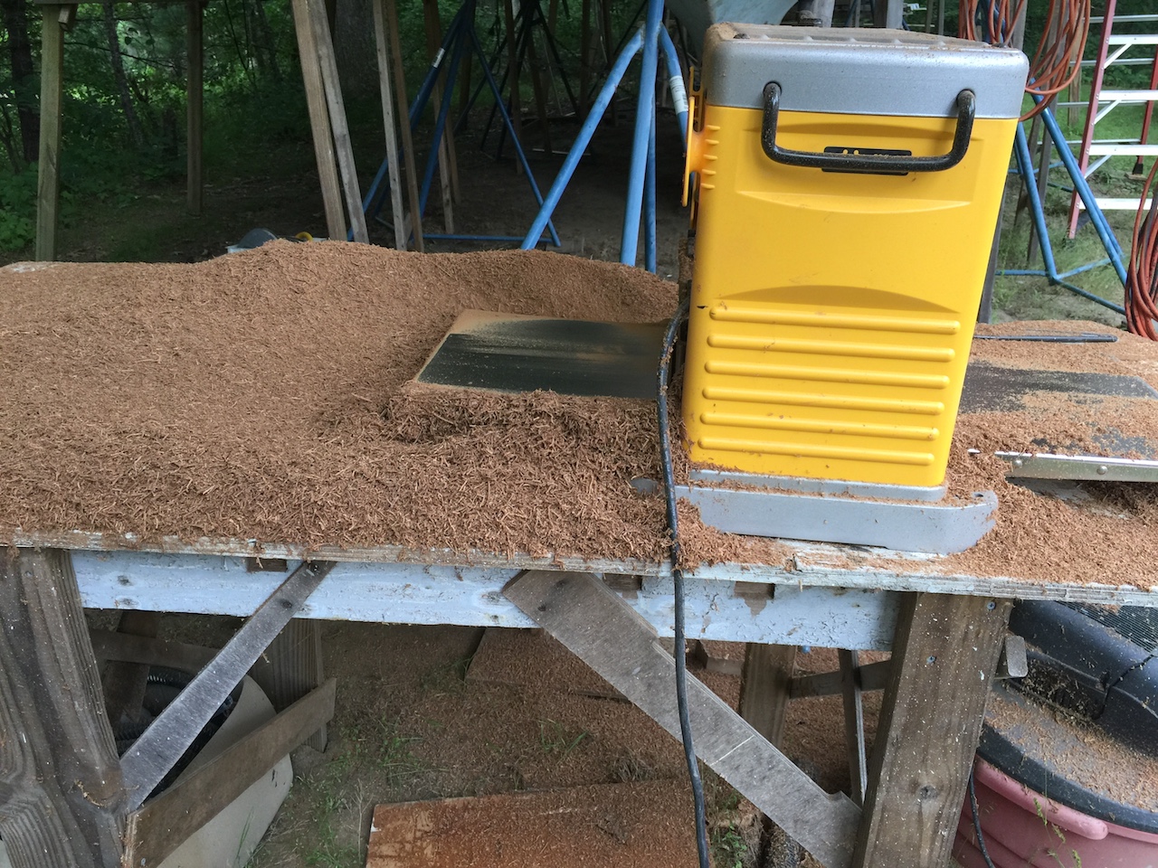
Normally, I’d appreciate the extra board feet, but in this case, it simply created bigger piles of planer dust.
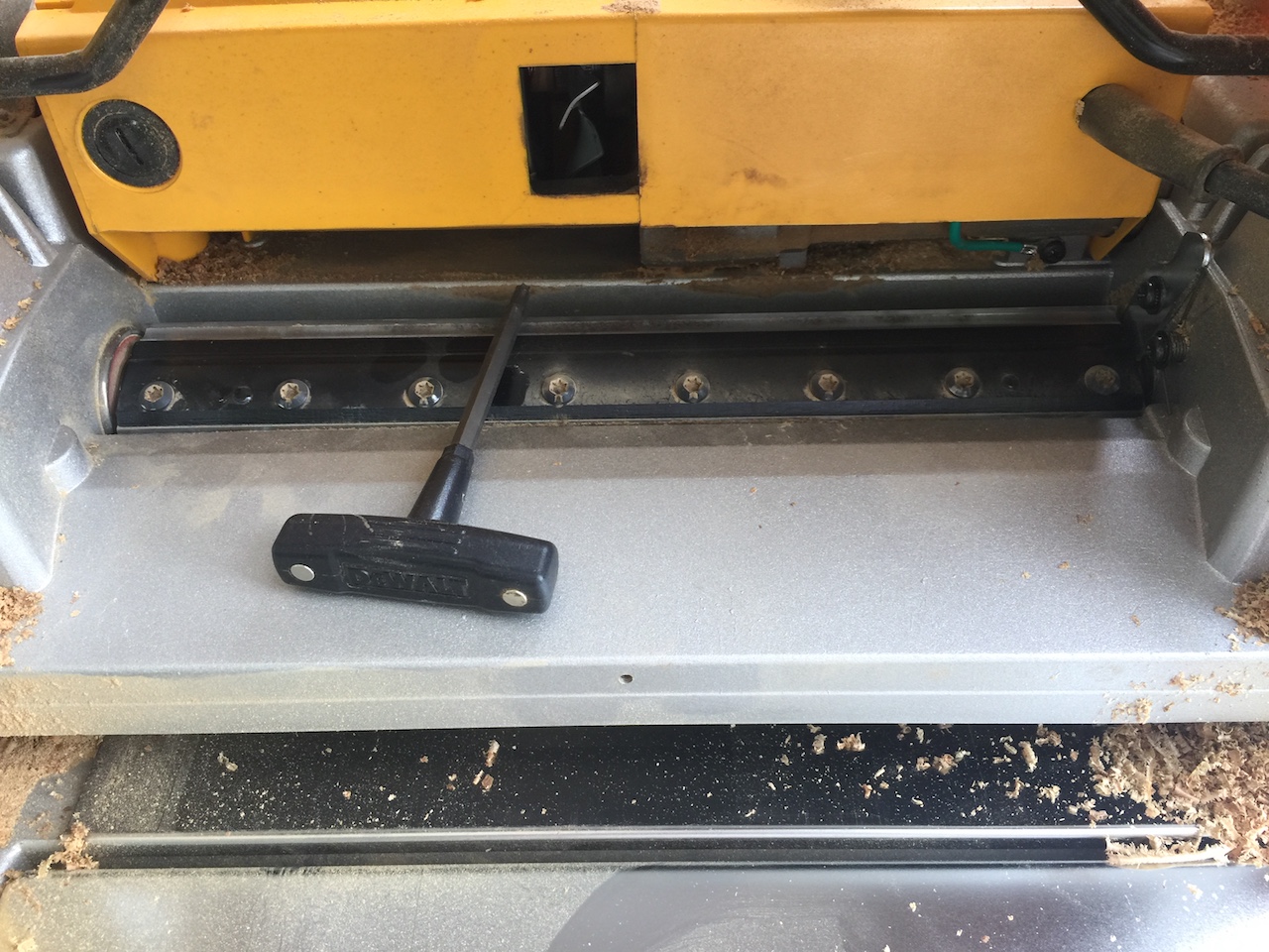
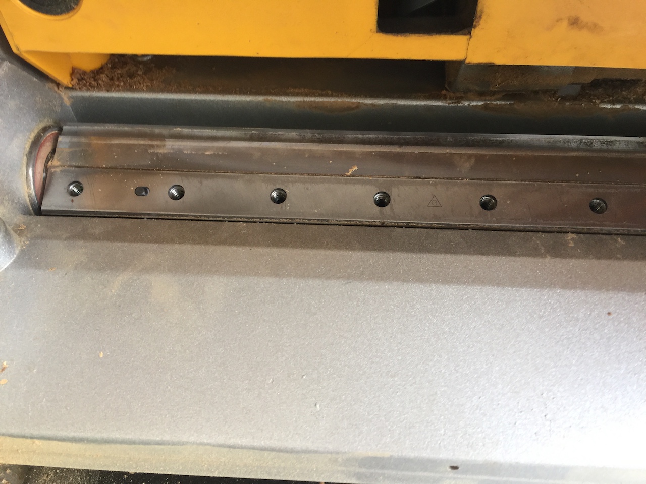
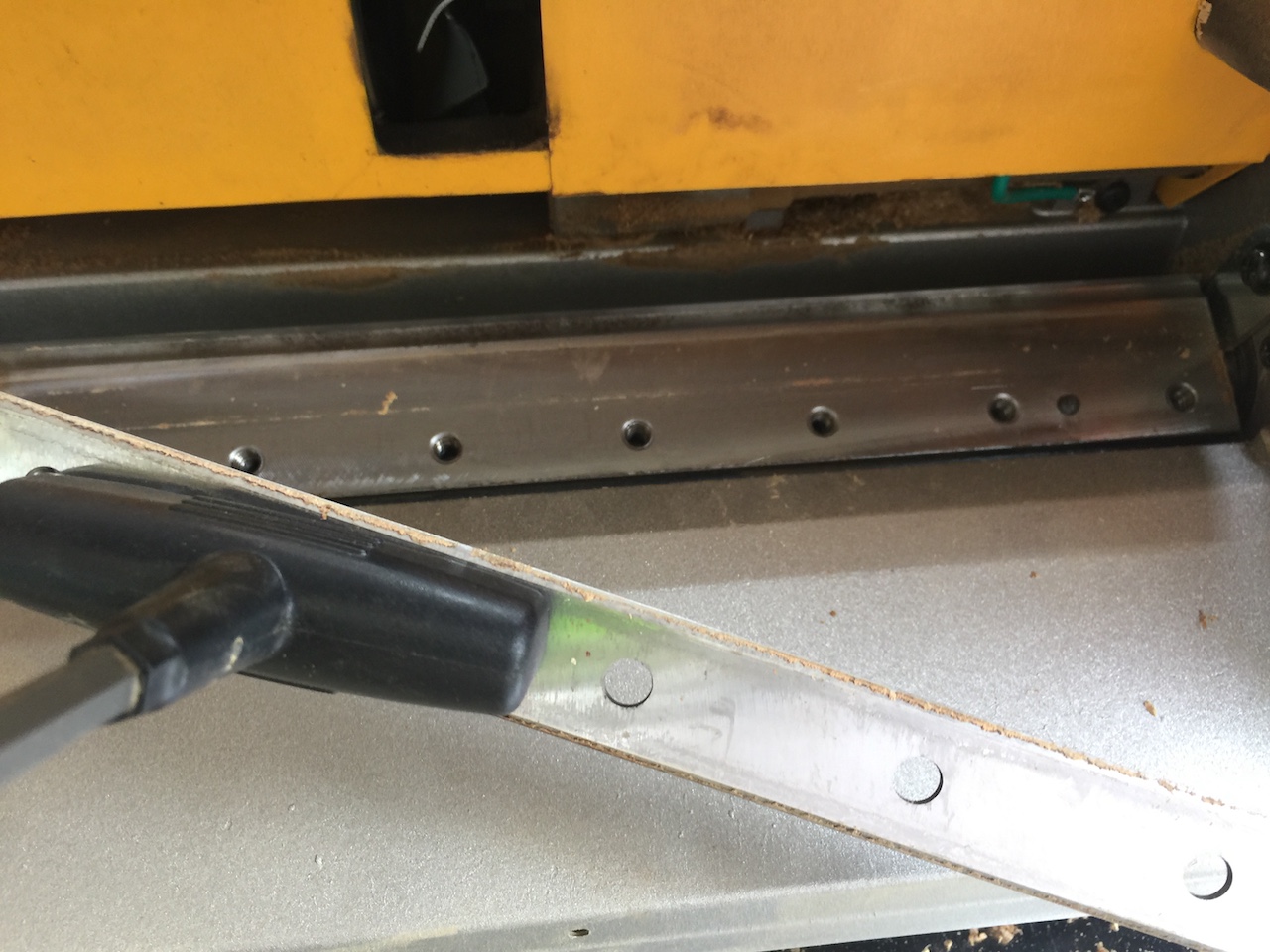
Teak is very tough on blades. One approach is to use carbide-tipped blades, which supposedly last 10 times longer than steel, but are about four times the cost. The other approach, which I took, was to sharpen the steel blades every so often. My planer has three reversible blades (that is, they can be flipped around for a second use before sharpening). Each blade is held in position by a cover piece and a number of bolts. The following three photos show some of the process of removing a blade.
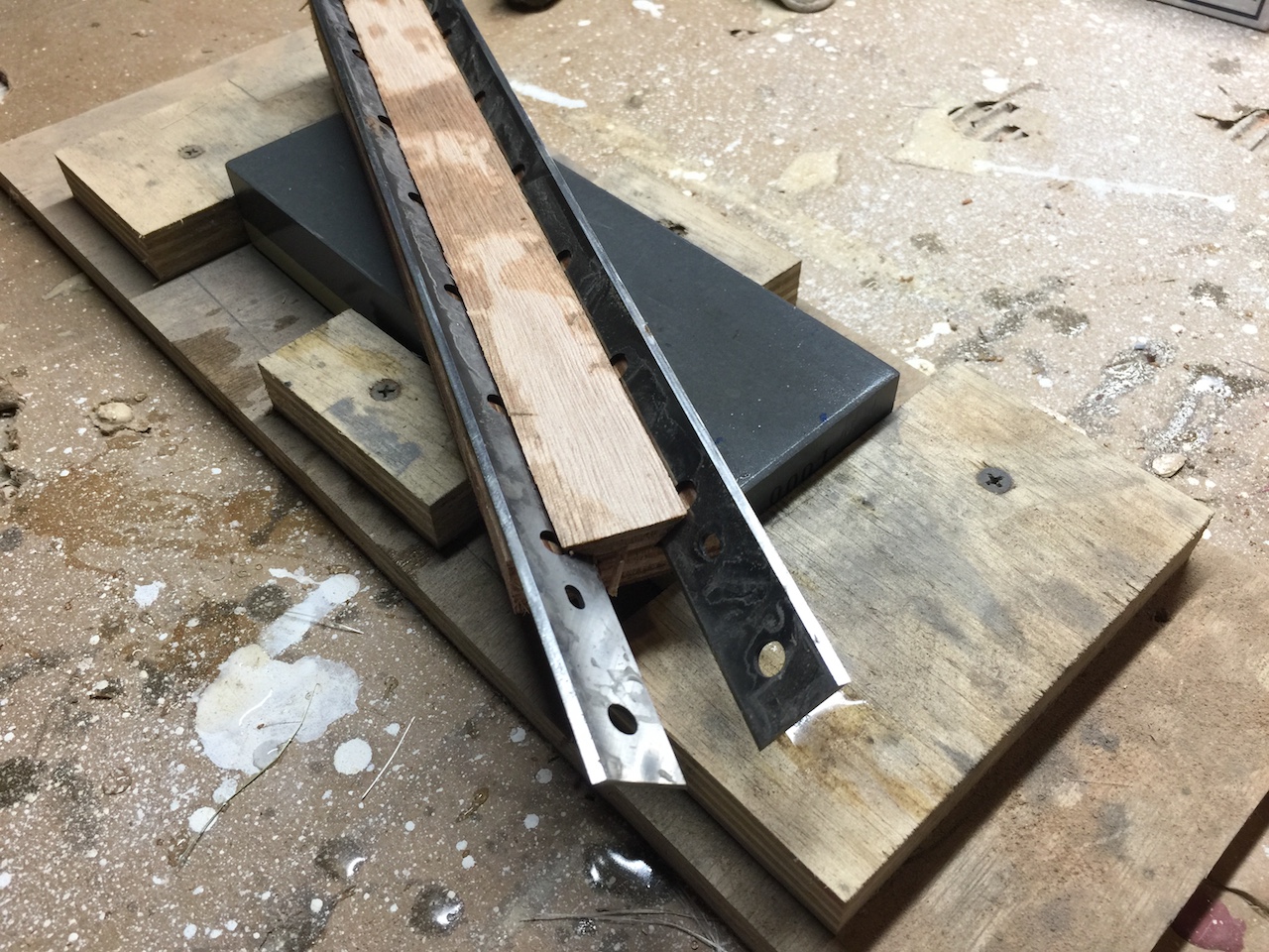
I found a YouTube video that explained how to make a simple jig for sharpening planer blades. The idea is to use the table saw to cut angled slots in a short piece of wood. With just the right angle, the blades will sit properly on the sharpening stone.
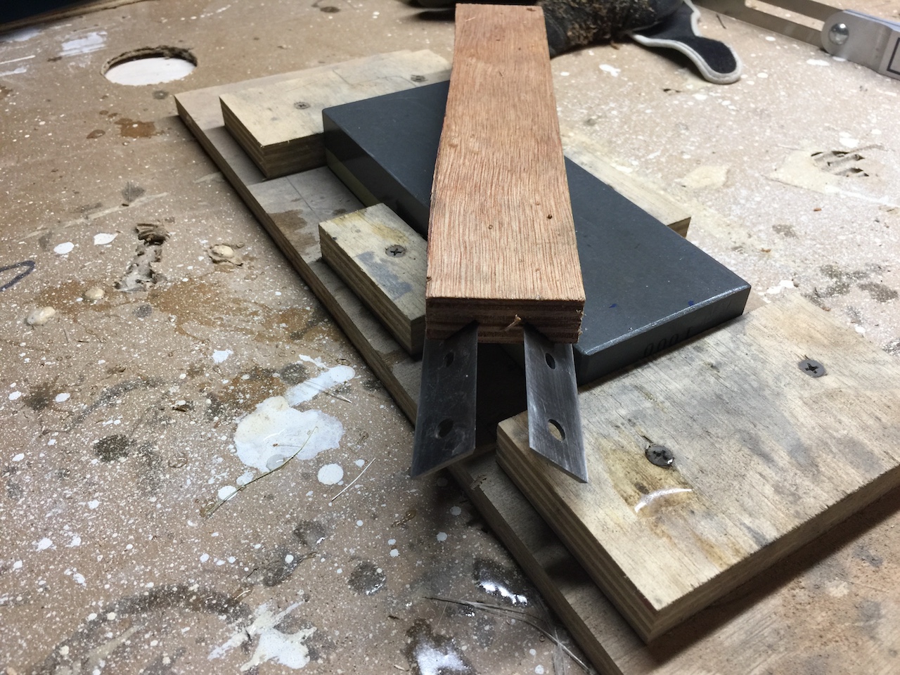
This technique proved fairly effective and I will continue to use it.
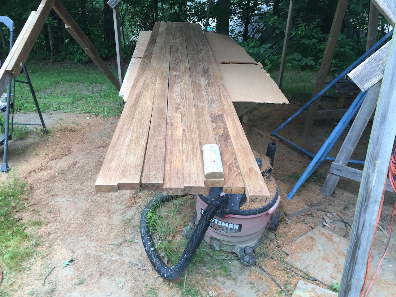
The planer takes off just a little bit at a time, so the process is iterative–set the planer height, run all the boards through, lower the height by about 1/64-1/32 inch, run all the boards through, and so on.
After a while, I compared a piece of the original cap with the new boards–not quite there.
Finally, after about three hours of planing, in which I sharpened the bladed three times, the height was about 1 1/8 inches, which is about 1/8 more than the original cap.
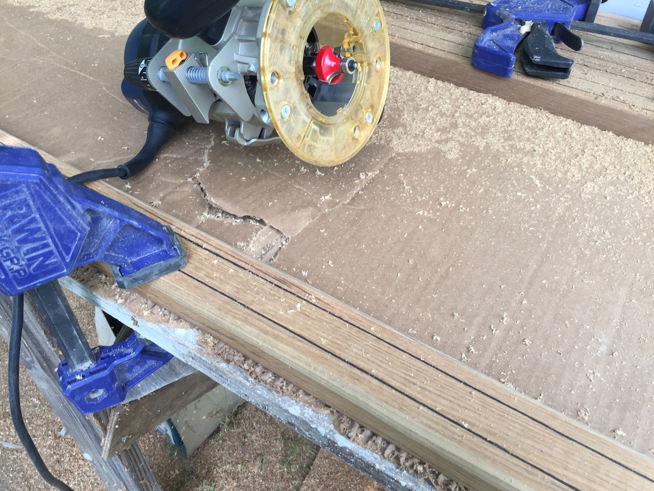
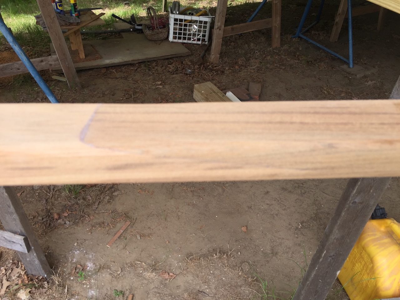
Here we are looking at the bottom side of one of the cap rail boards. (Better-looking side up was the rule for determining which side was the bottom.) The lines I’ve drawn were intended to help center the boards during installation, but have since been lost via sanding, and will not be redrawn because I’ve decided on a different approach. I used the router with a round-over bit to take the corner off the bottom edges.
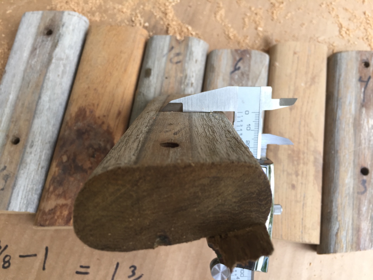
Here we are looking at cross sections of old and new. I was slightly concerned about the asymmetry of the old piece; it is thicker on the left than the right.
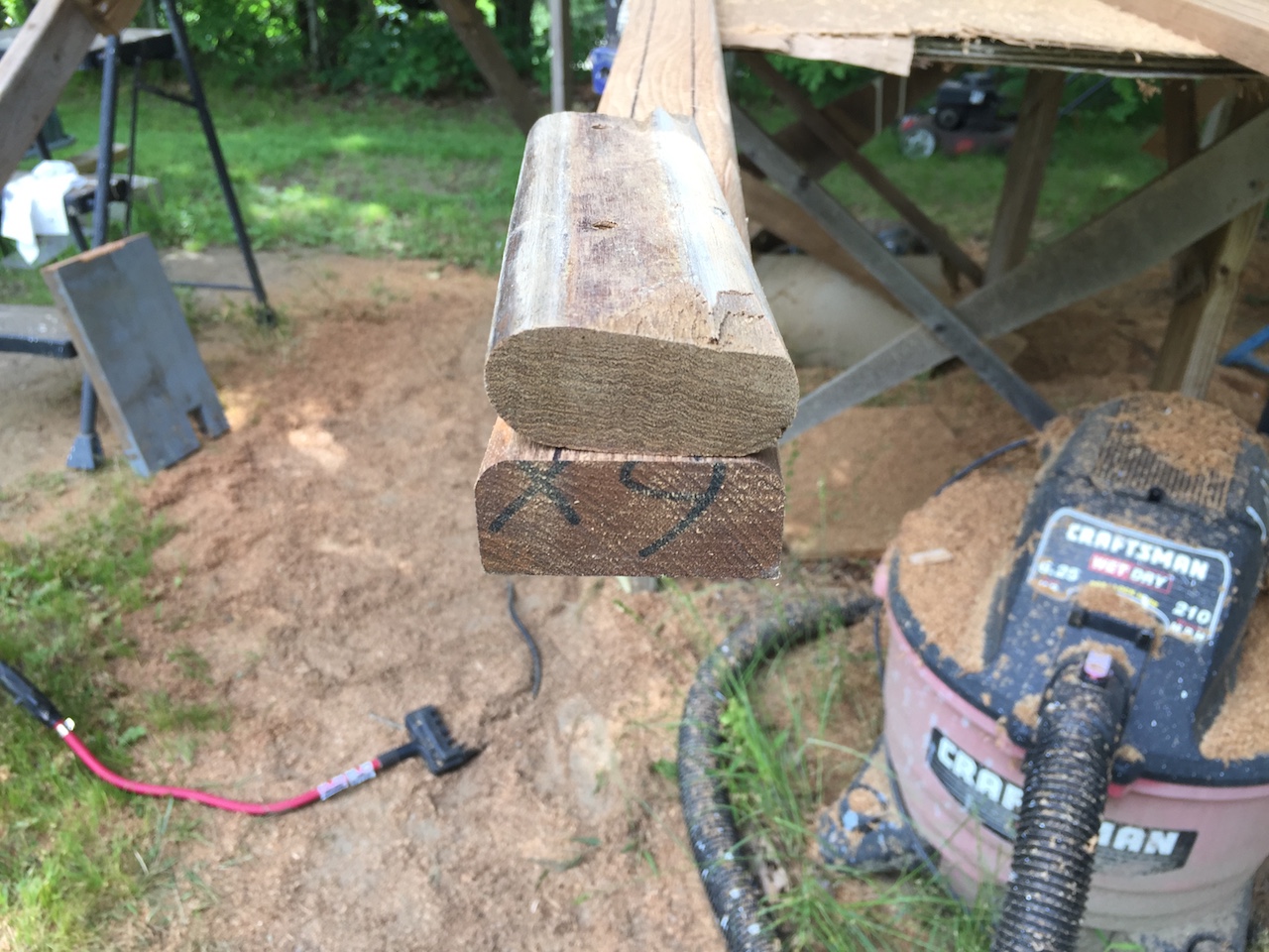
I considered three possibilities:
(1) The asymmetry was a mistake.
(2) The asymmetry was created by 40+ years of wear and maintenance.
(3) The asymmetry was by design, in which case I would have to carefully consider whether I should try to replicate it.
I started by checking if the top of opposing toe rails were parallel. I laid a level across the boat, just forward of the Samson post.
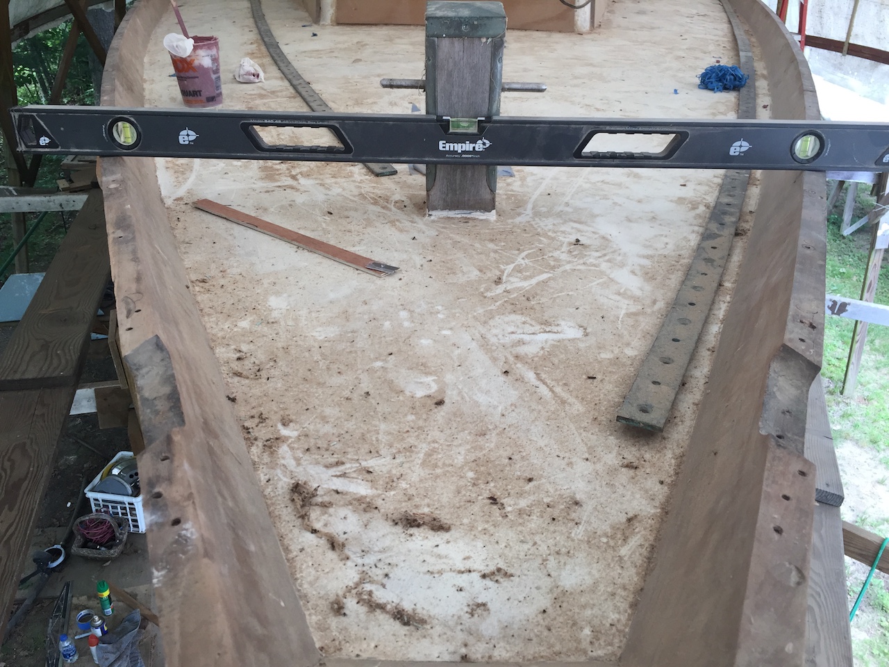
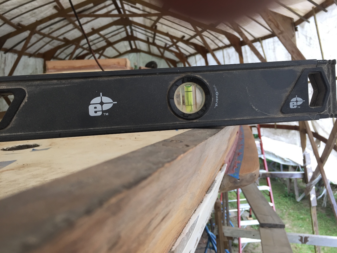
They are almost parallel, but not quite.
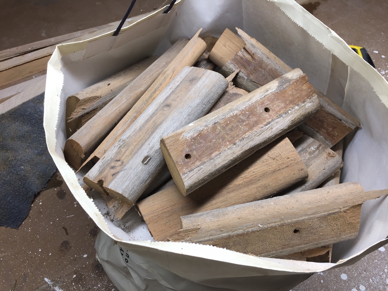
Next, I located the bag containing the pieces of the original cap rail and picked out some random pieces.
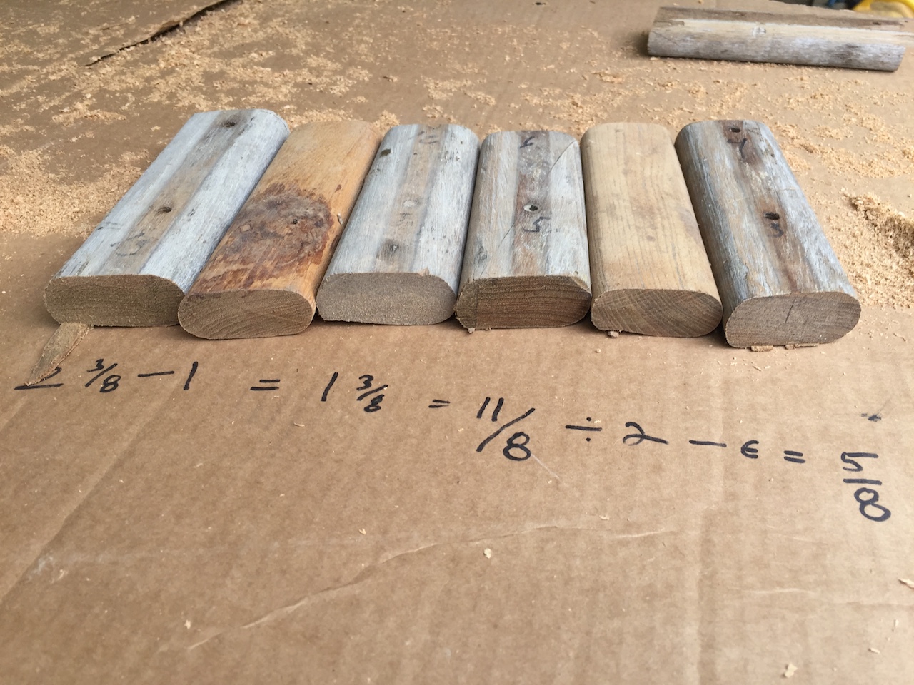
Here are those pieces, side by side, so we can see the cross sections. We are looking at the top sides, and four of these pieces were under the genoa track, as we can tell from the holes and the unworn part over which there was a teak strip under the genoa track.
The parts not under the genoa track are a bit thinner, which makes sense because, over the years, they could be sanded all over, and much more easily,
As a last check, I used the calipers to confirm that the middle part of the top and bottom surfaces were parallel, and as far as I can tell they were.
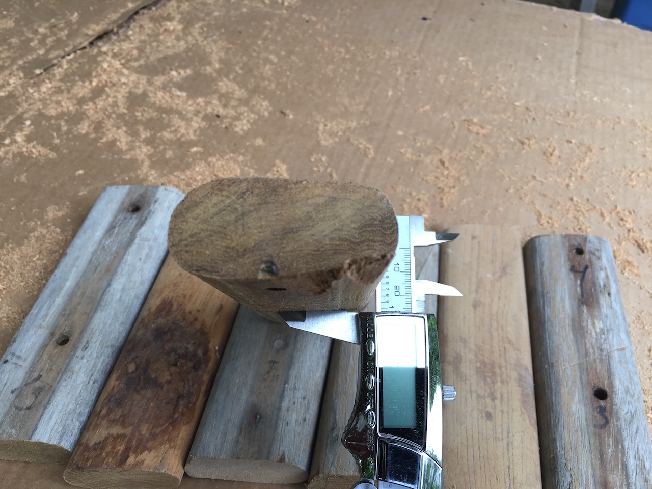
My conclusion from all this checking is that I don’t believe there was ever any built-in asymmetry in the cap rail, and even if there were I’m not going to worry about it.
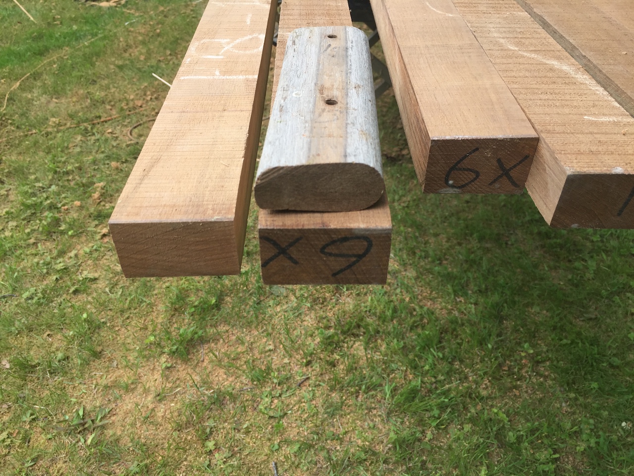
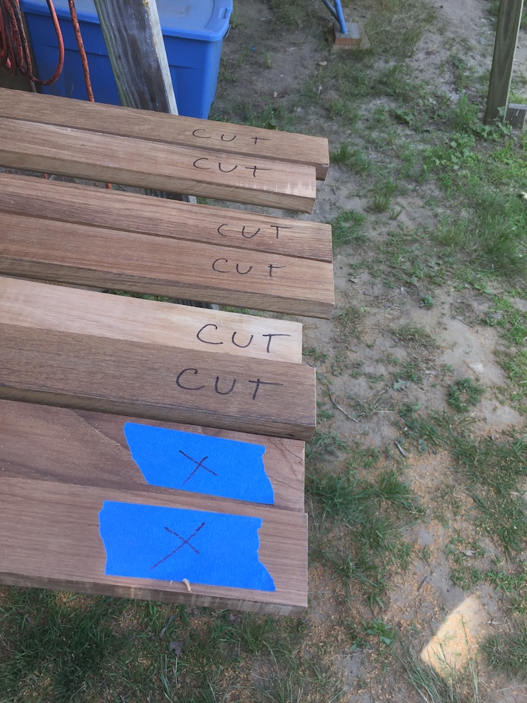
The original cap rail was made up of multiple lengths (I forget how many) that were joined at the ends by notches. I decided to join the new pieces with scarf joints. In 2016, I used a scarf joint to join two pieces of plywood, which you can review HERE and HERE. For the cap-rail project I used the table saw to make the cuts. First, I carefully labeled the boards.

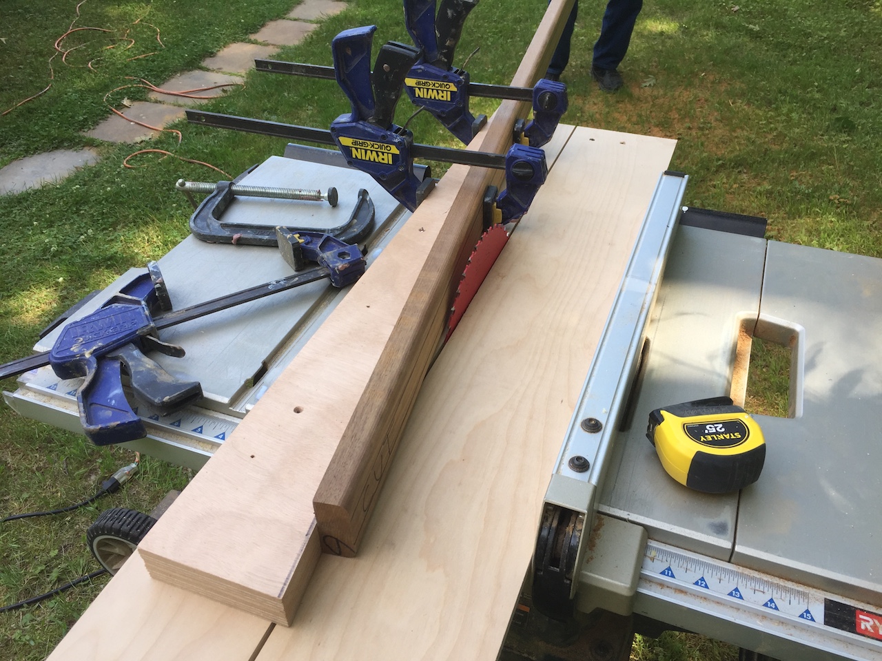
Next, I built the jig shown in the photo below. These board are 11 feet in length, so two people are needed to make the cuts.
After the cuts were made, I cleaned them with acetone, and let them sit overnight. After cleaning them again, I coated the joint surfaces with unthickened epoxy, then thickened epoxy.
I made some simple jigs that held the boards in position for clamping.
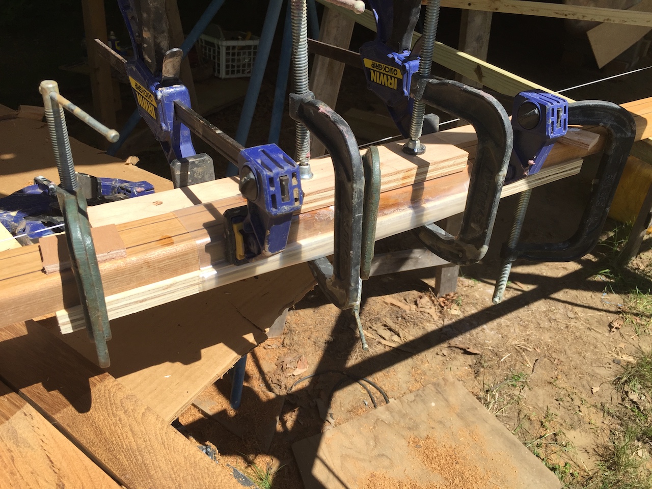
Each side (port and starboard) of the cap rail will be four pieces joined end-to-end, so I built some temporary supports under the boat to provide a long working area for clamping the joints.
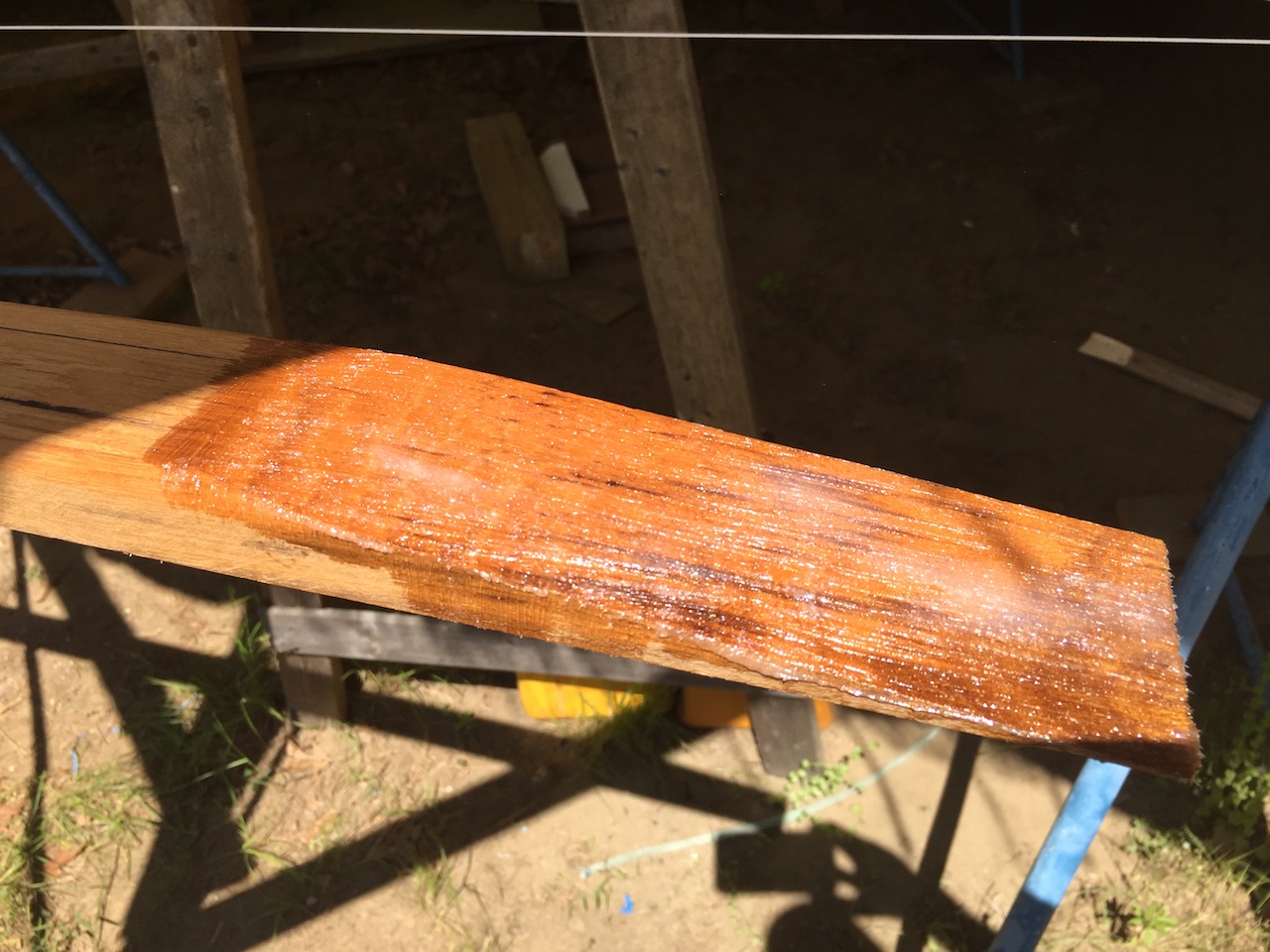
Here is a joint just out of the clamps.
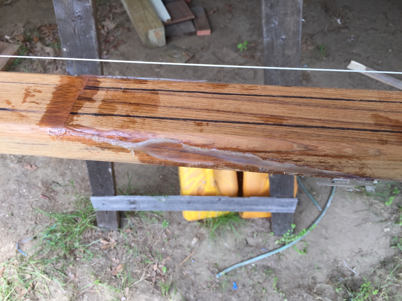
The next steps were sanding the joints, sanding the entire lengths, rounding over the top edges along the whole lengths, and more sanding. The blurry photo below shows the almost-finished product at the location of a joint.
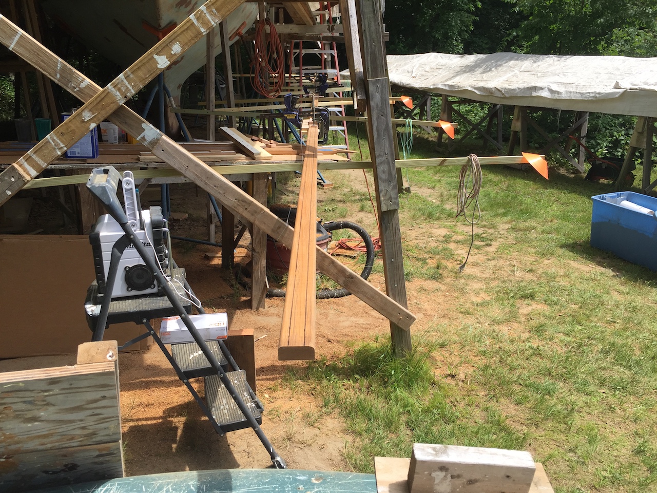
The rails are very flexible perpendicular to the wide sides, but not as much the other way. Getting them on the boat was easy.
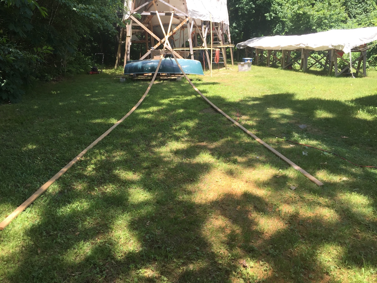
Getting them to bend the hard way was less easy, but aided with clamps and 2x3s.
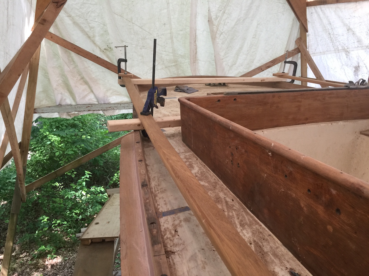
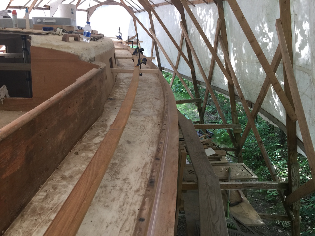
I’ve been working them into shape each day, little by little.
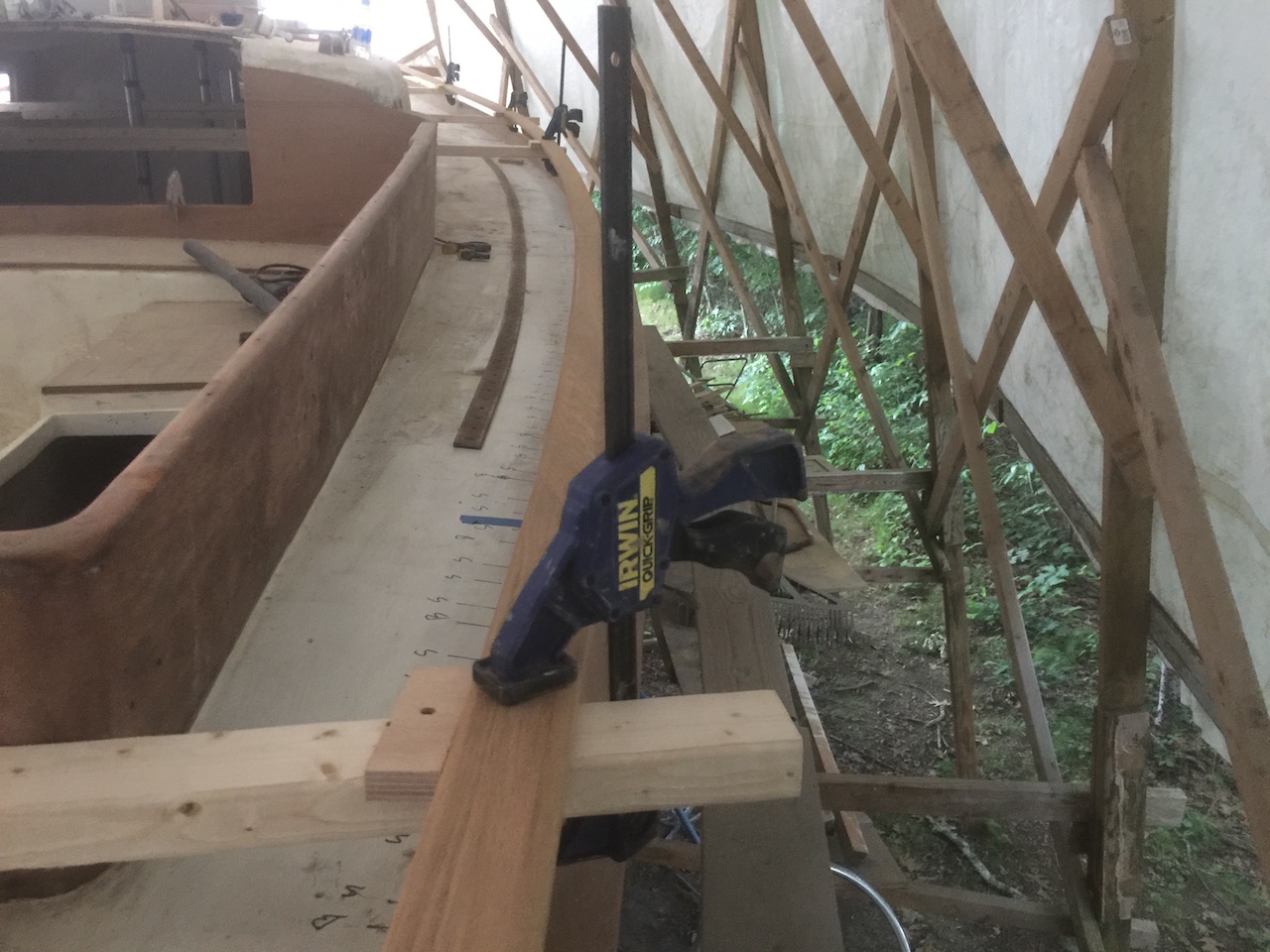
I’ll leave them like this until I’m ready to fasten them to the toe rail. In the mean time I have a few odds and ends to take care of. One is to determine the exact location of the genoa track so that toe-rail bolts and old screw holes don’t interfere with the new genoa-track screws. In the photo above You can see where I’ve marked on the deck the locations of the holes and bolts. More on that later.