8/5/18: Exterior Woodwork III
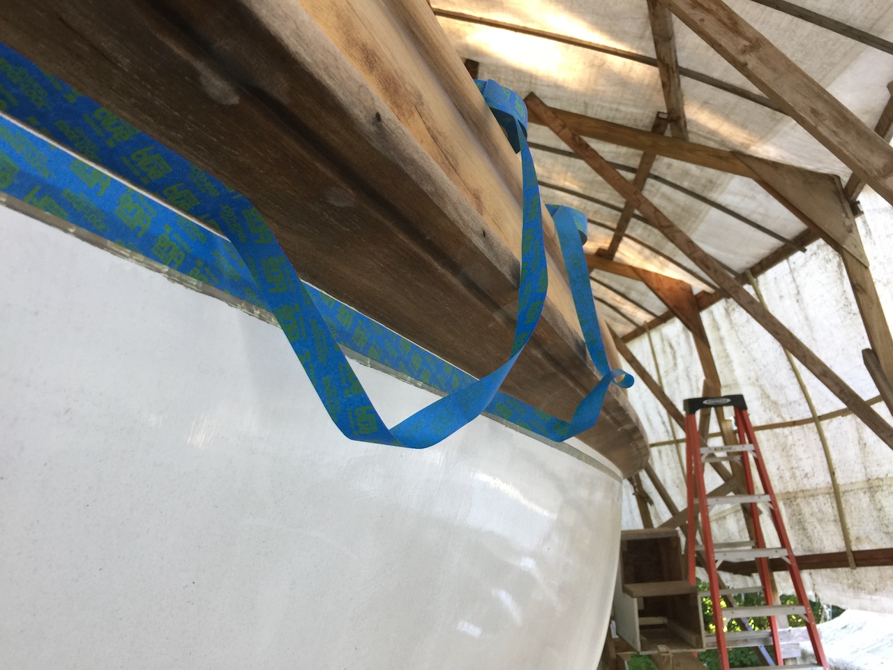
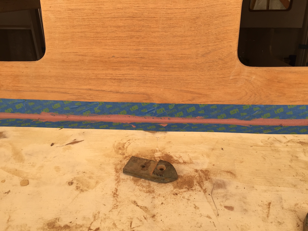
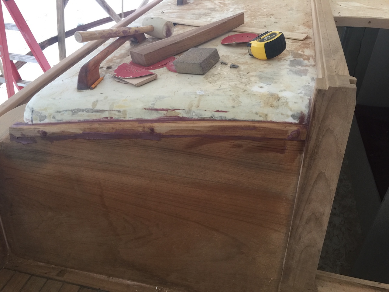
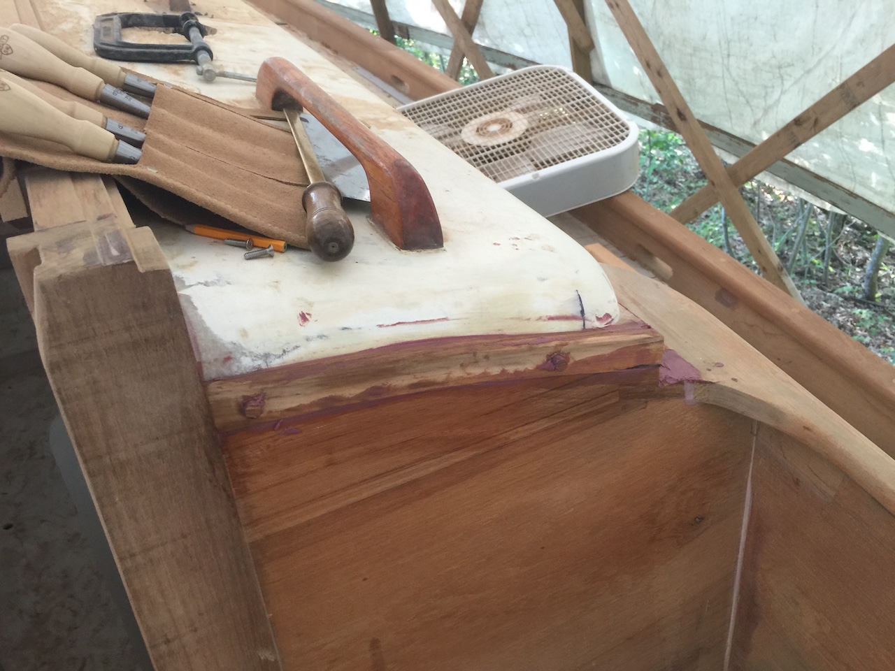
The cap rail was bedded with Dolfinite, which is a bedding compound whose purpose is to provide a watertight seal, not to “glue” a joint. After cleaning up the squeeze-out (and discovering that there were plenty of places where there was no squeeze-out), I decided to run a very small fillet of thickened epoxy along the seams where the cap rail and toe rail meet, and also where the rub rail meets the hull. This job began by taping off the surrounding wood.
Next, I used a small syringe (a WestSystem product) to apply the epoxy, and I smoothed over with a gloved finger.
I removed the tape before the epoxy dried. (I assure you that letting the epoxy dry before removing the tape is a bad idea.)
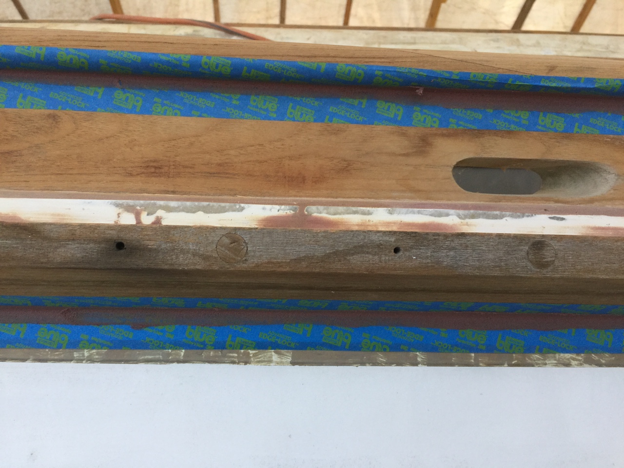
After a little sanding, the job was done.
I also filled the gap at the lower edge of the cabin-house teak.
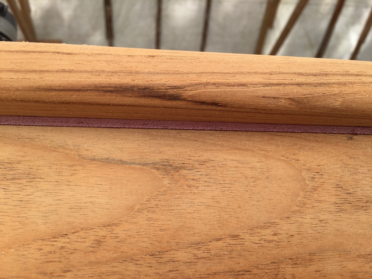
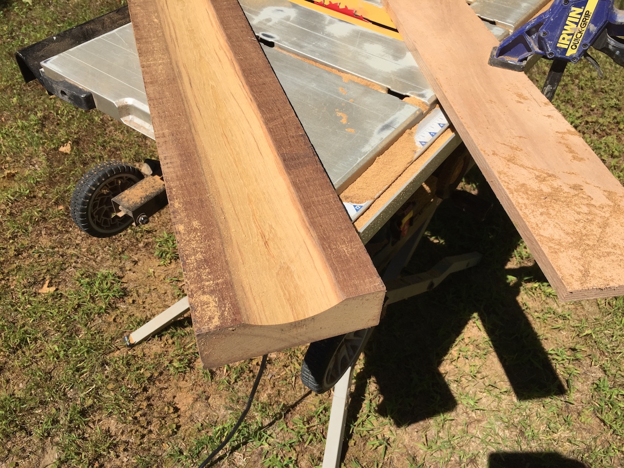
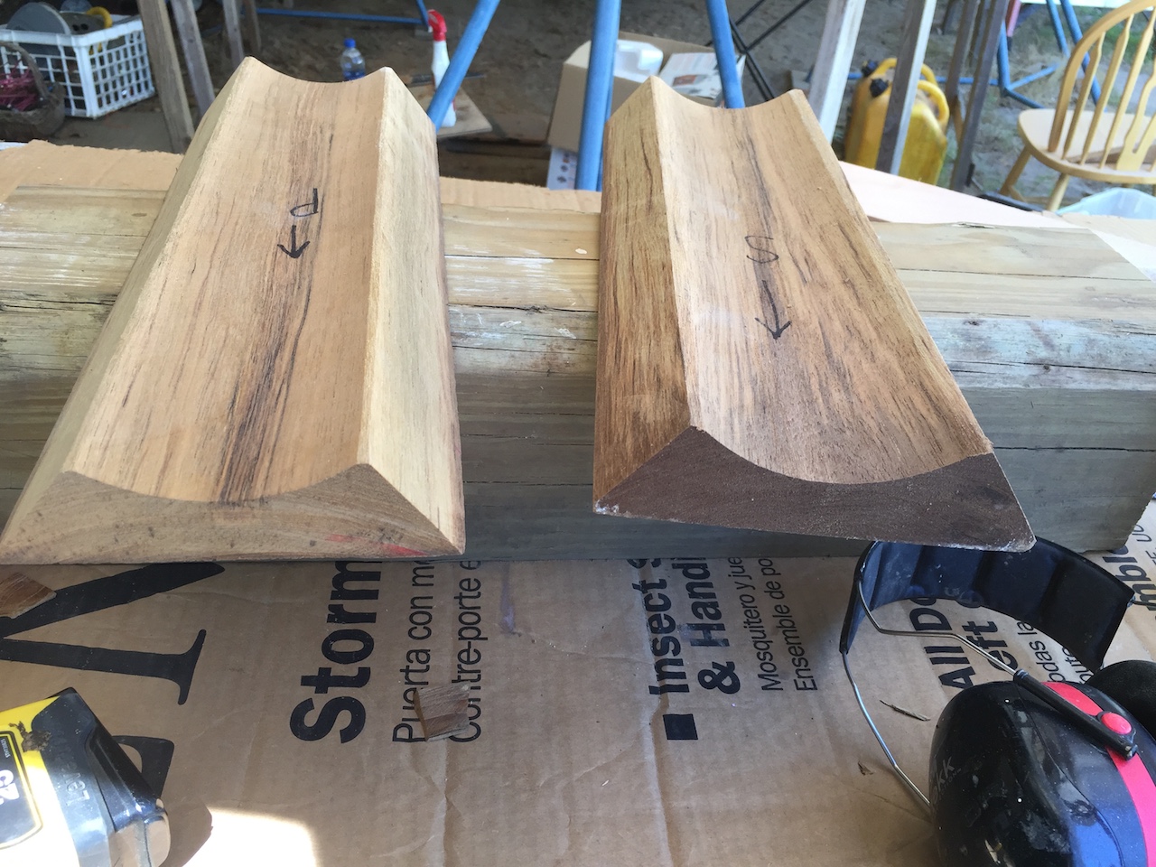
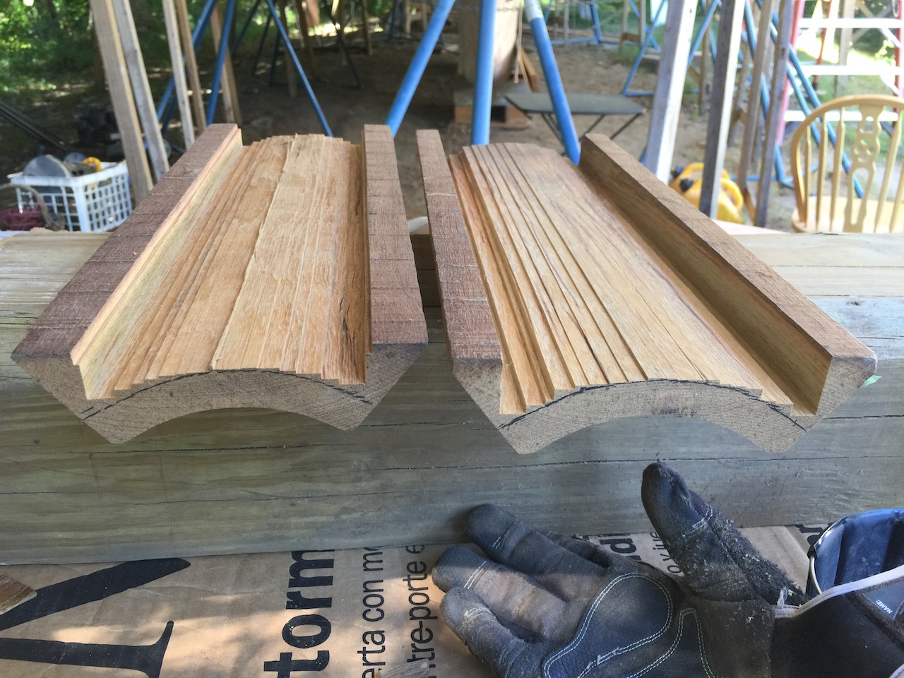
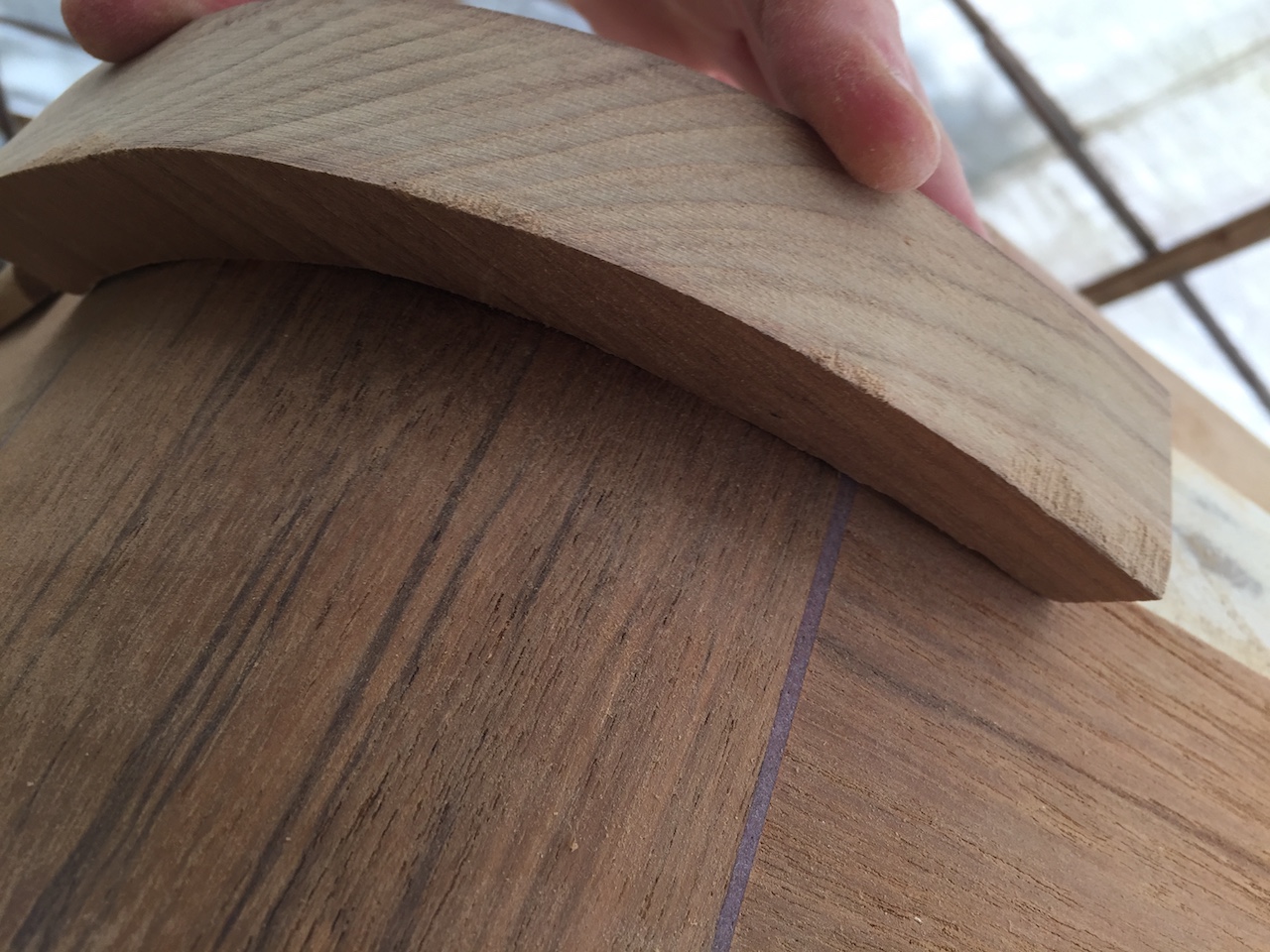
Back in 2014, I was thinking about molding, but this summer I’ve moved on to actually doing something about molding. The photo below shows a piece of the original drip-molding, and a piece I milled up from some scrap teak.
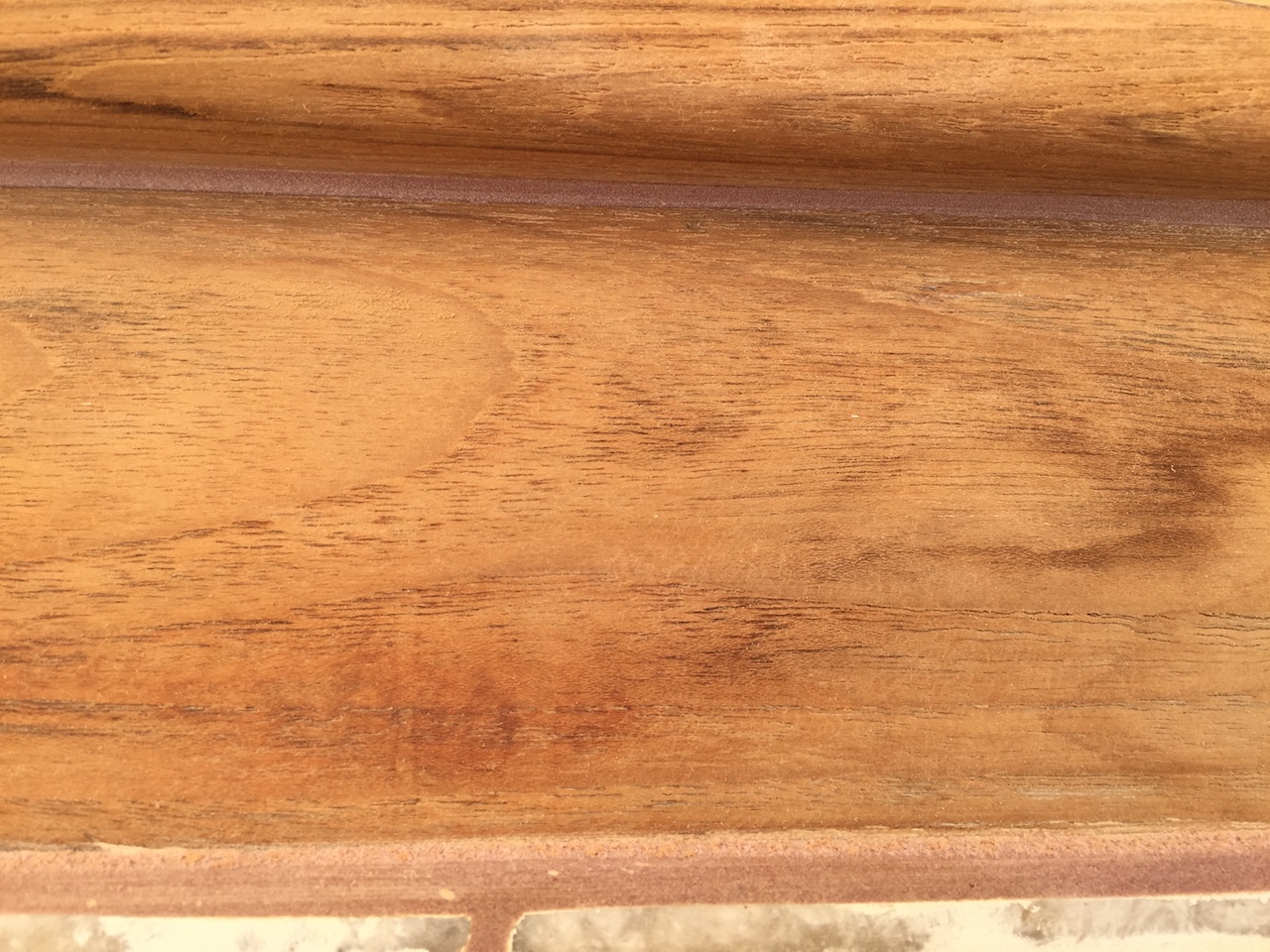
Here I’ve tried a slightly taller profile.
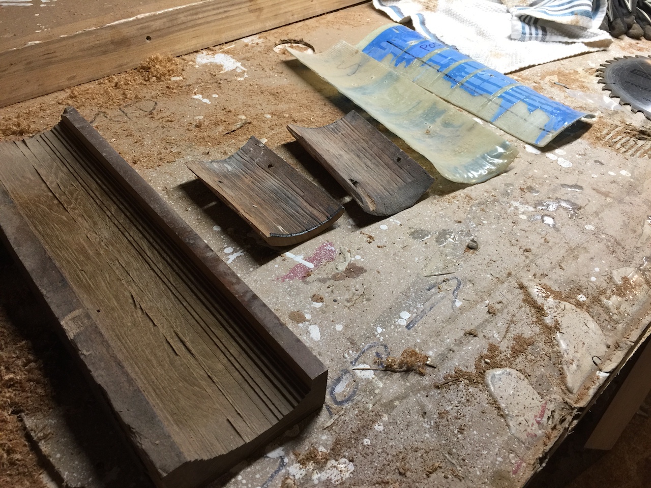
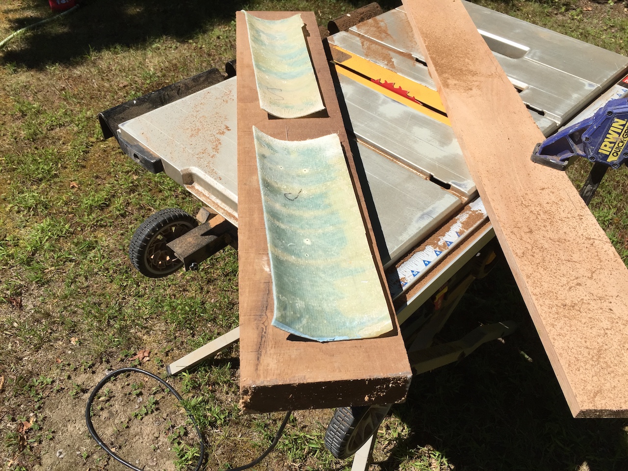
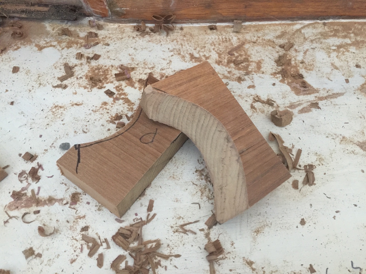
Before proceeding with molding, I decided it was time to finally tie together the forward cabin teak with the side teak by making the corner-pieces. The photo below shows (left to right) an old mockup I attempted years ago, one of the two original pieces (cut in half), and some fiberglass molds I made from the cabin house just in case I needed the exact shape (I didn’t).
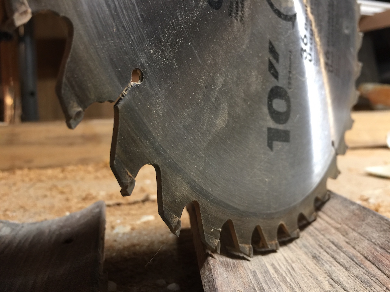
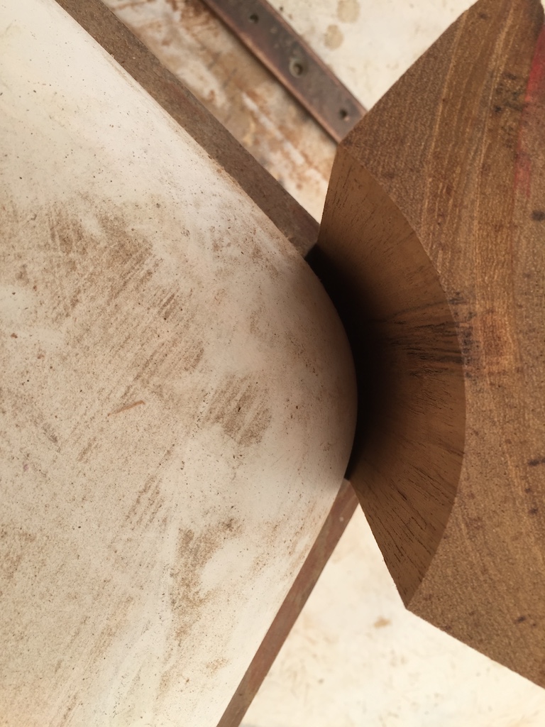
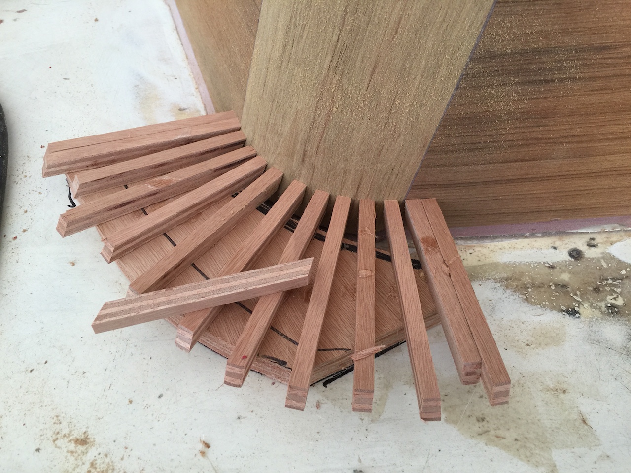
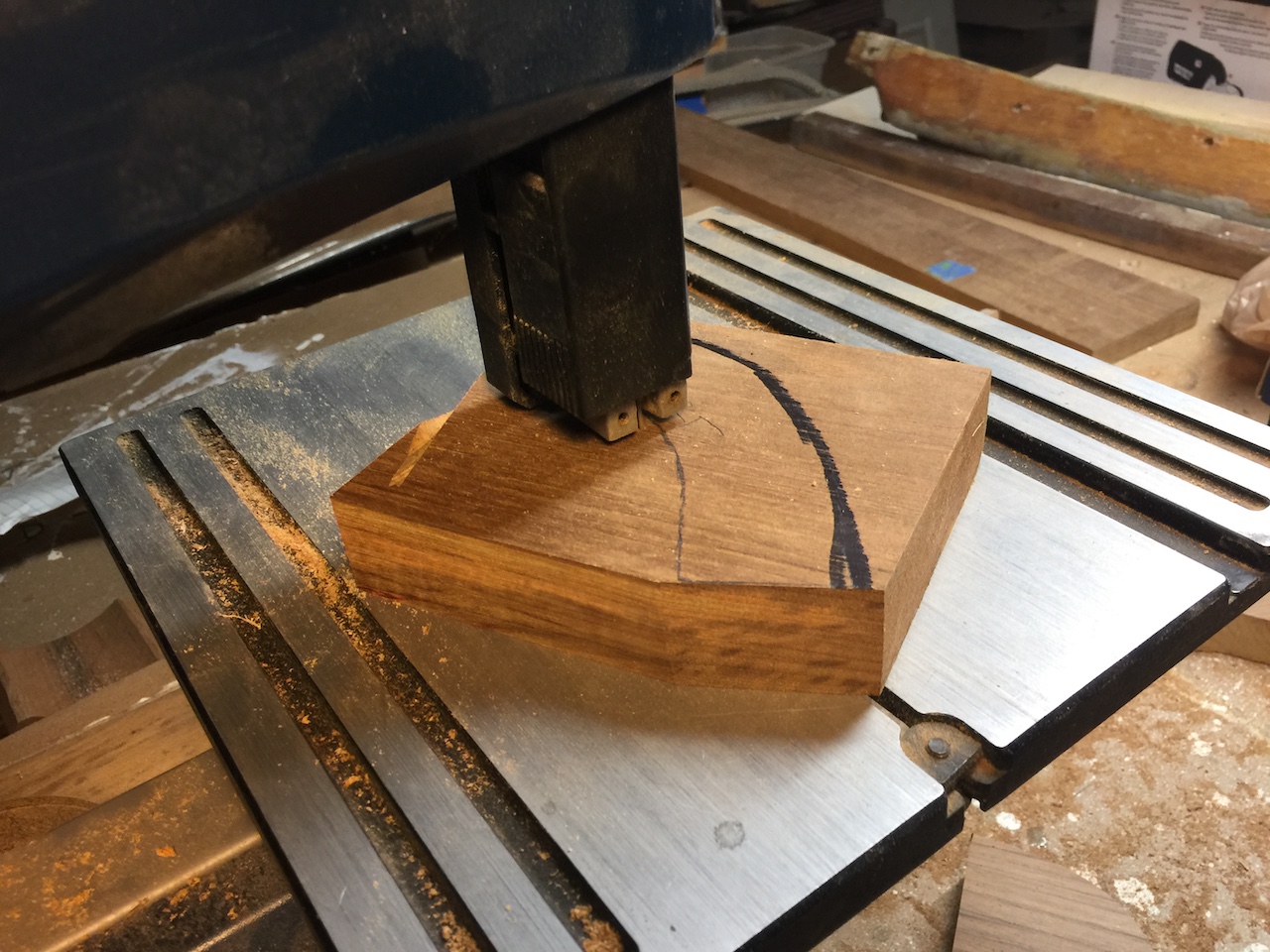
On the advice of a friend, who is an expert in the industry, I rounded out the insides of the pieces using the table saw. You can see below that a 10″ blade has a too-small radius…
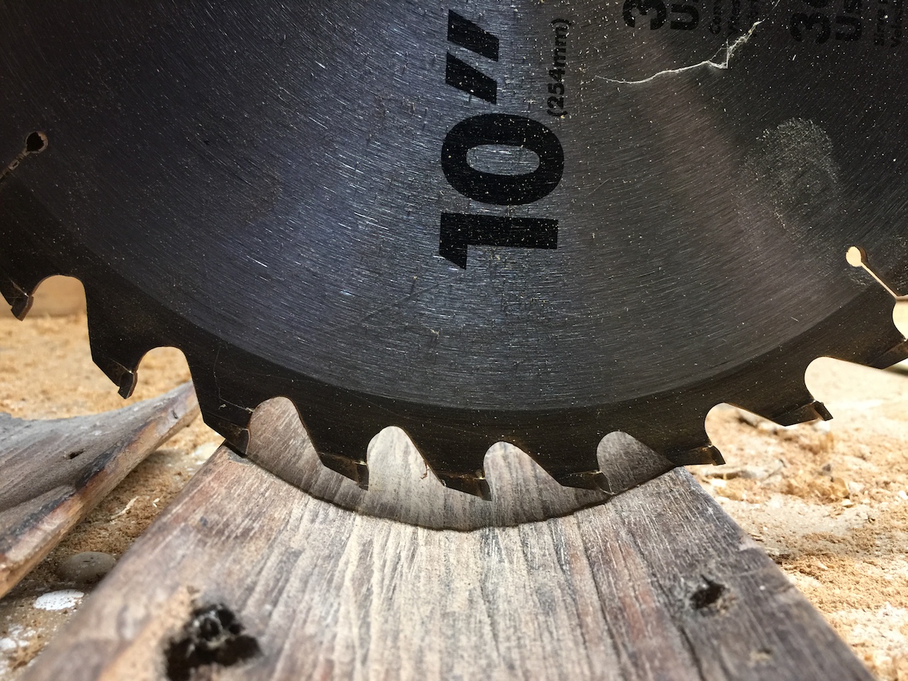
…that is, if the piece is run across the blade perpendicularly. One can control the radius of the cut, however, by running the piece across the blade at a different angle.
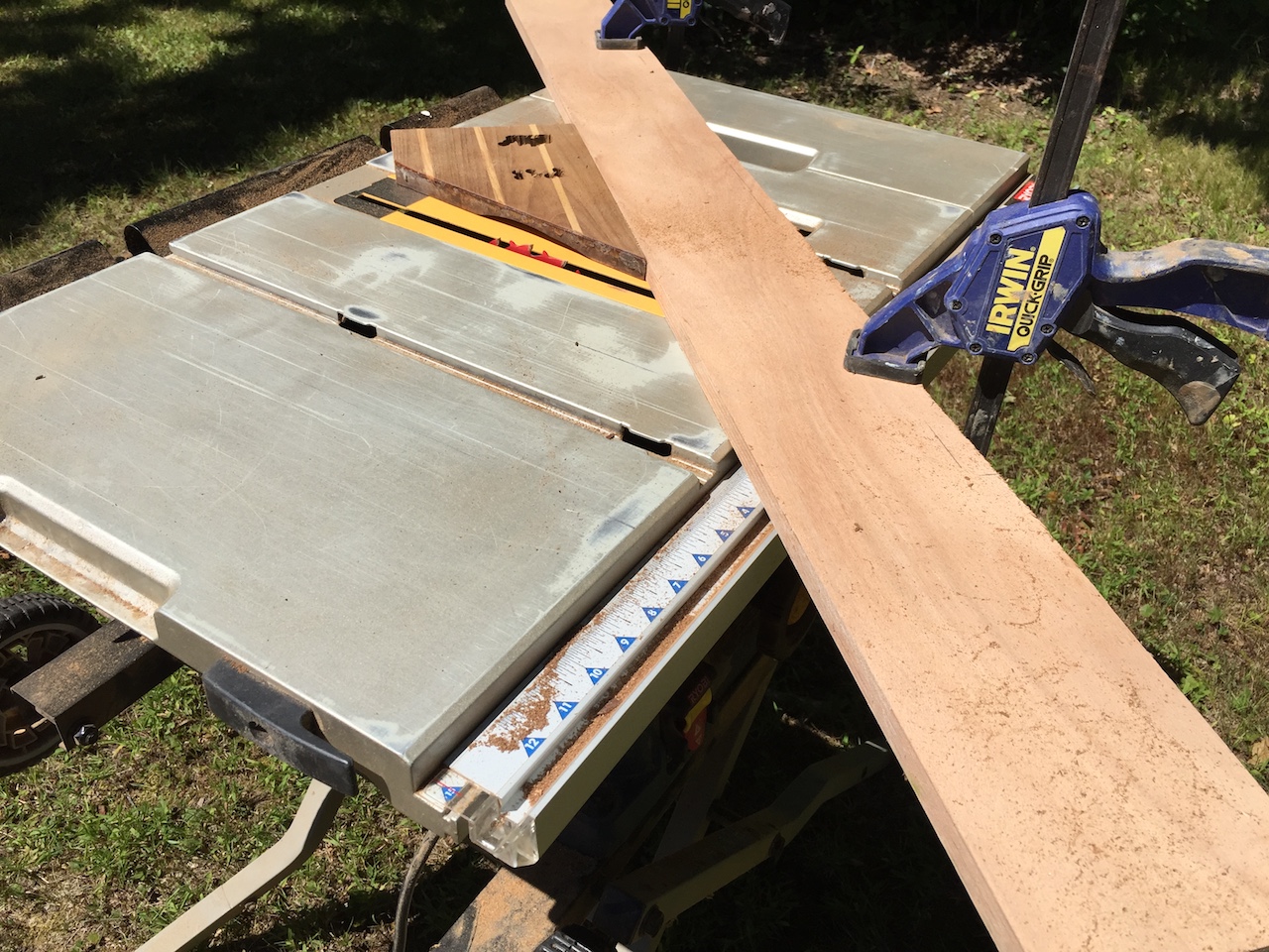
This job required a temporary, adjustable fence.
I started with a scrap from the original cabin sole, and ran the scrap over the blade over and over again, gradually increasing the height of the blade.
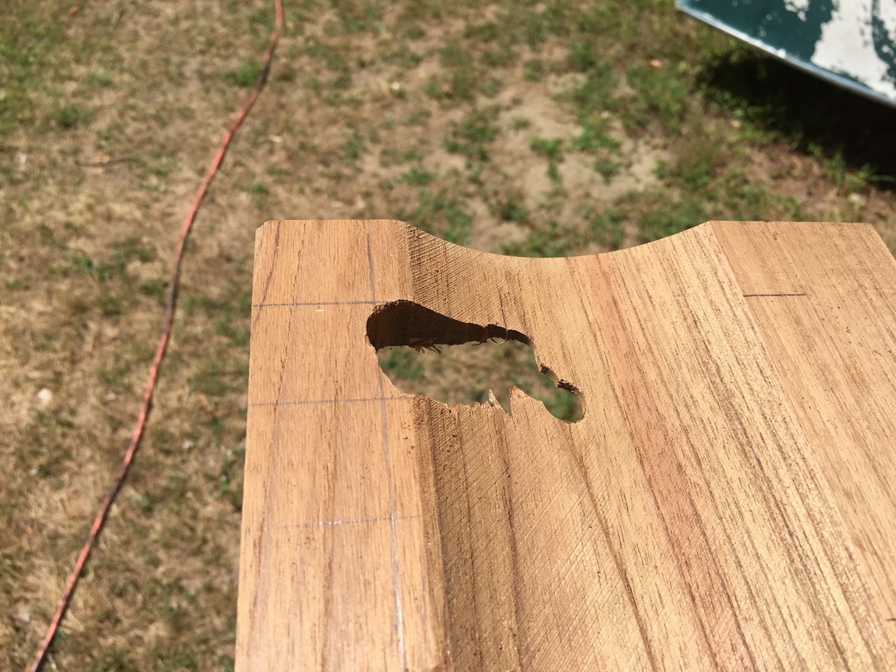
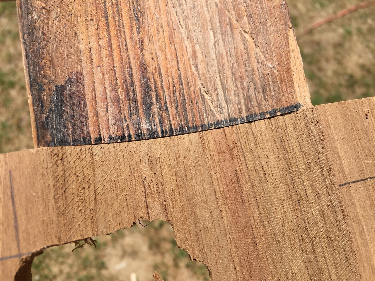
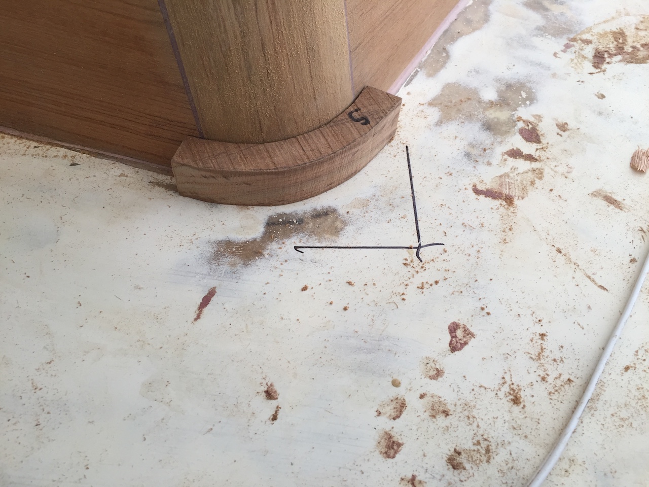
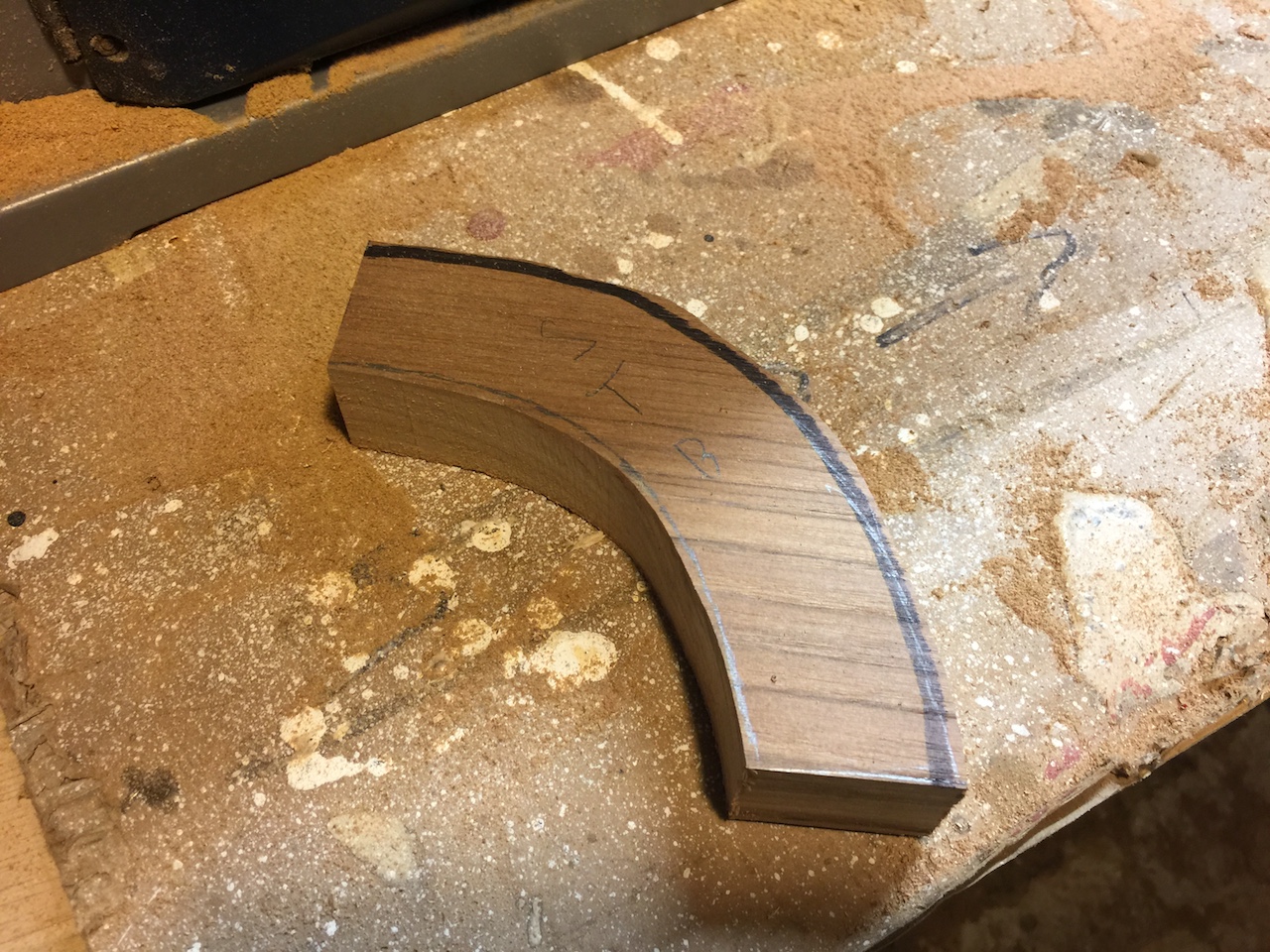
With a little trial and error, I found just the right angle. You can see below that the radii of the original and new match perfectly.
Next, I selected some teak stock and made the cuts in the same way.
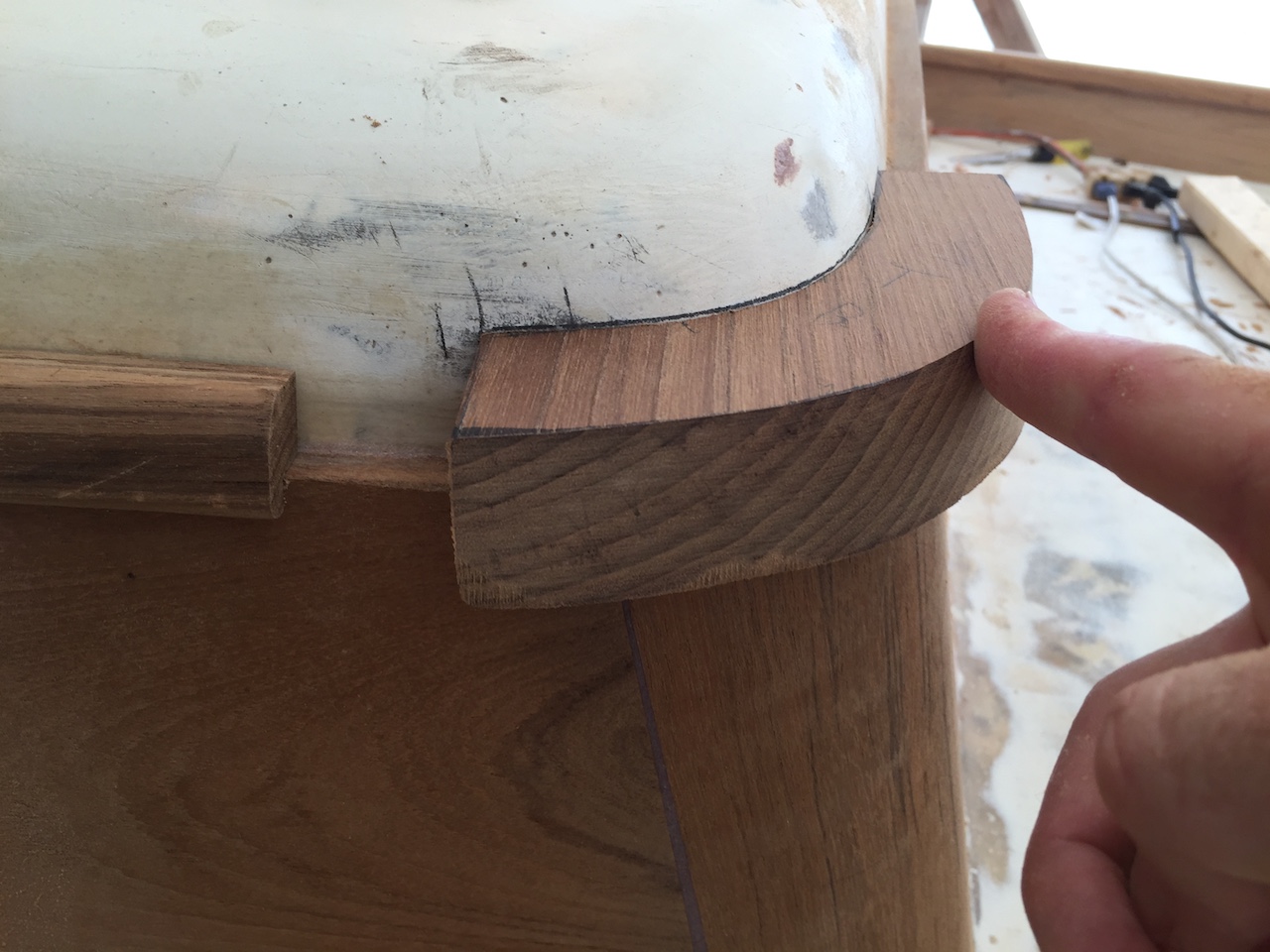
I removed some excess wood by using the table saw in the usual way, and then tested out the fit.
Next, I traced the 1/2 inch thickness along one end, and used the table saw again, this time with the dado set, to remove most of the material on the outside of the pieces.
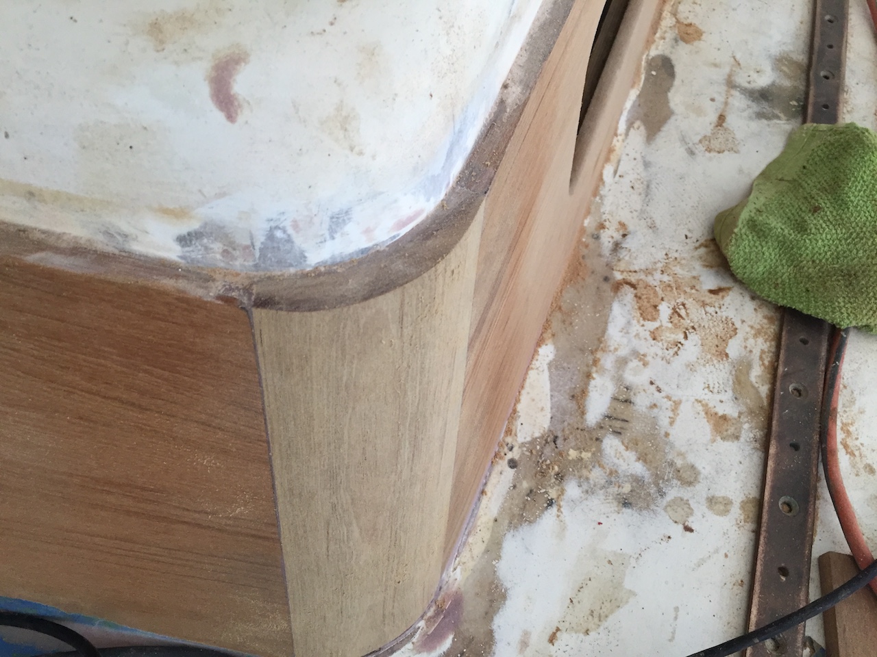
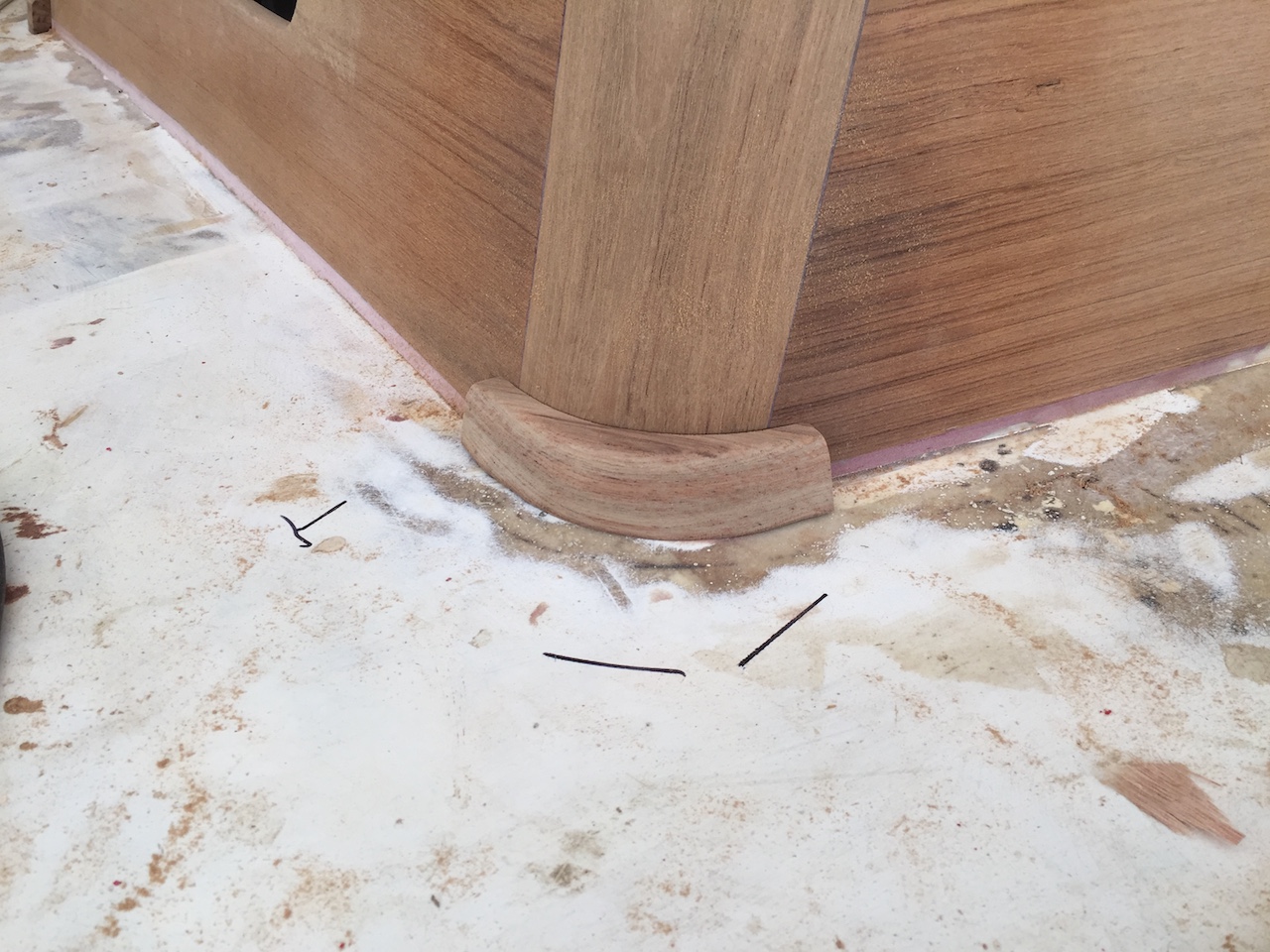
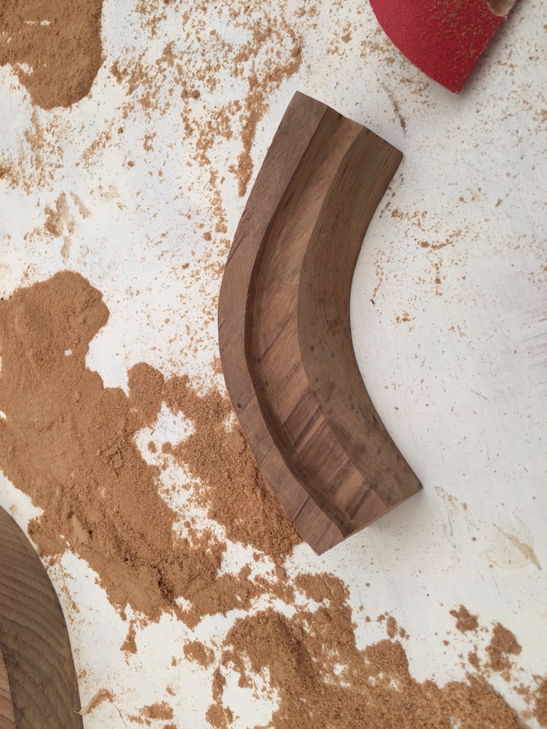
Eventually, and with a whole lot more fussing and fiddling than is evident here, I got the pieces glued up…
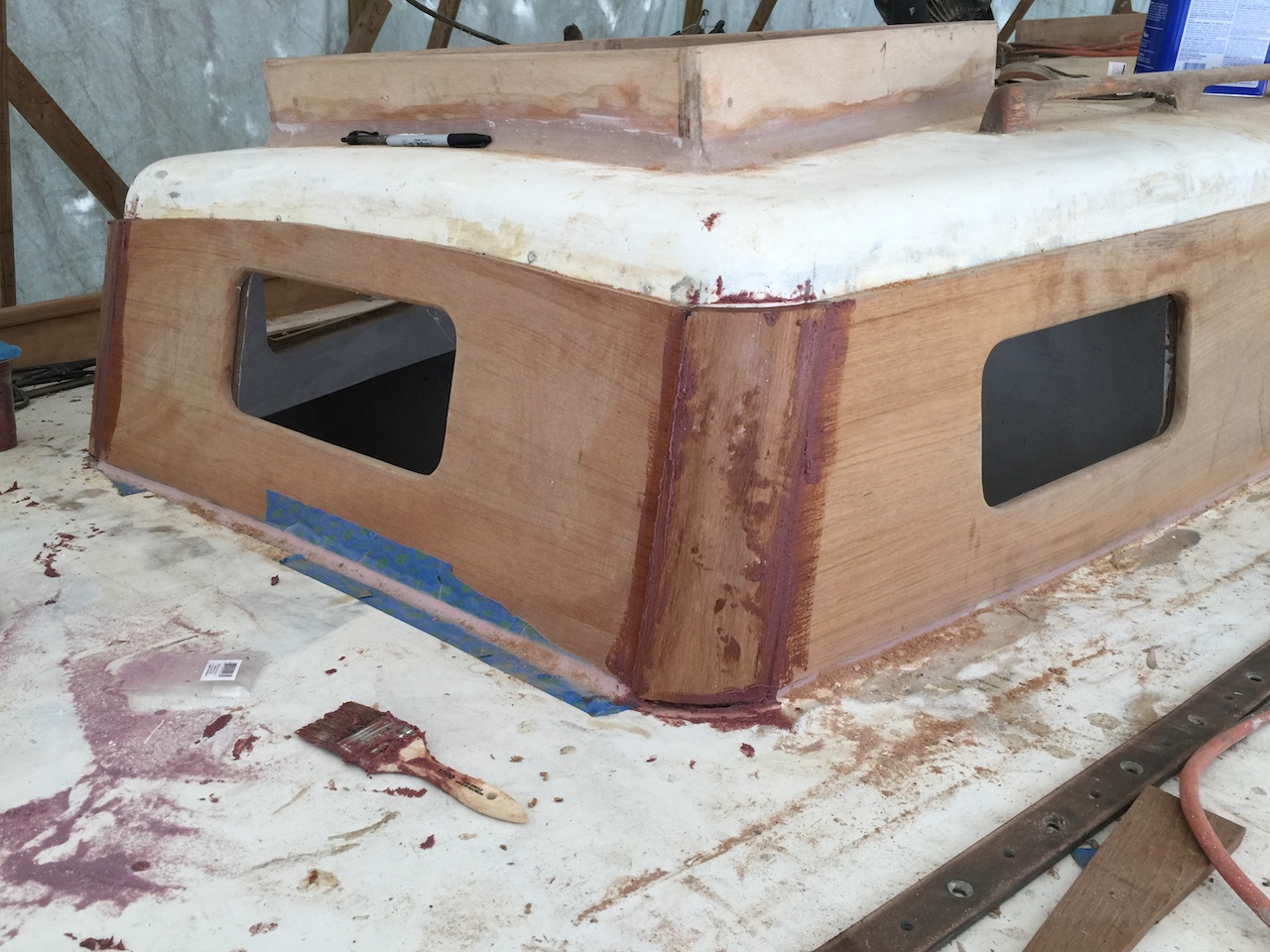
…and sanded round and smooth.
You might notice that the new teak appears lighter in color. The following information is from HERE and helps explain some things:
When teak is first milled, it can have a blotches and streaks of color appear. This appearance will last a few months time to the consistent golden color that people are used to from teak. What happens is that certain pigments in teak are light sensitive, so when they are first exposed they change colors.
To get the consistent golden teak color make sure to let you teak sit out in the sun. In fact, at most of the mills where new teak is processed, they specifically layout teak boards in the sun to help even out the coloring.
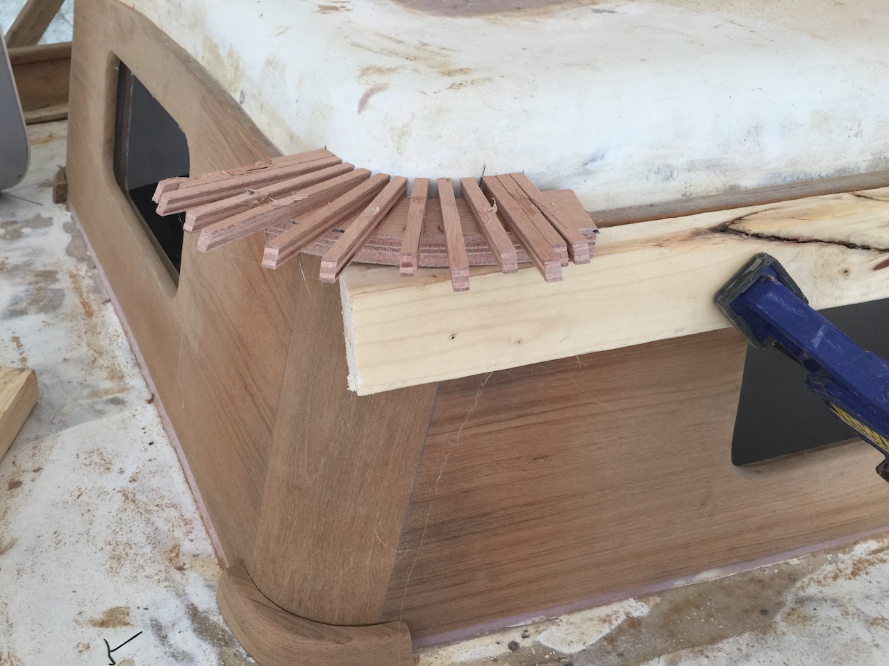
Next, I made patters for the corner molding on the bottom edges.
Finishing these pieces required a lot of work with the bench sander.
The drip molding also needs to round the corner.
The little-used band saw gets some work.
The drip molding overlaps the boards, so it requires a lip.
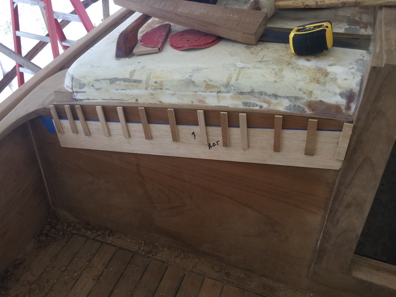
There are two corners on the aft end of the cabin top, too, and there is the additional complication of how to tie in the cockpit coaming. Duplicating the original design would have been impossible, but I was able to utilize the two original pieces that mated the top of the coaming and the cabin top.
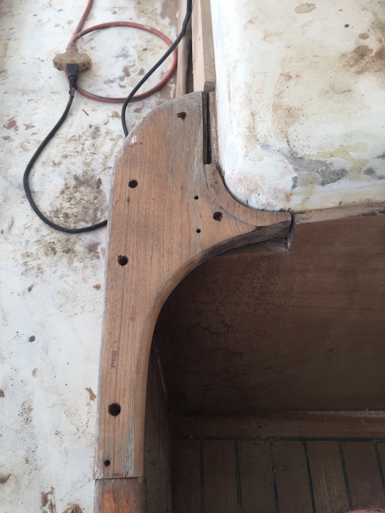
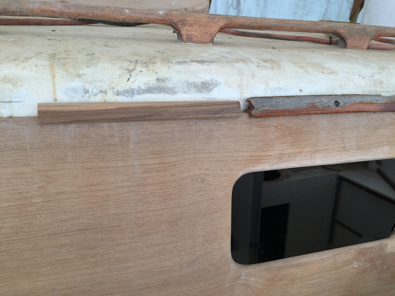
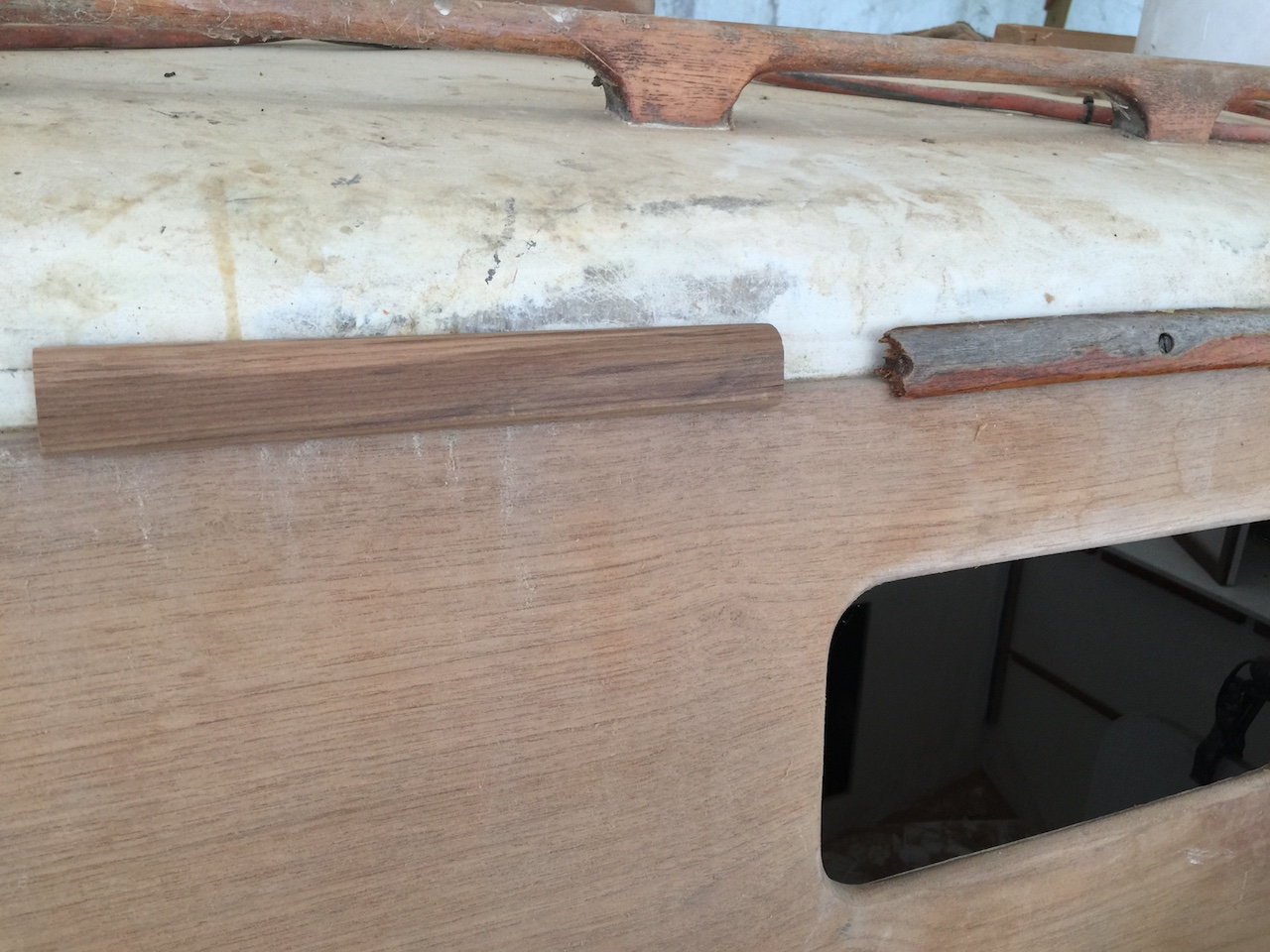
This job, like many others, began with a lot of looking and thinking. Eventually I had a rough Idea of what I was going to do. I began by removing the last of the original cabin-sides teak, and you can see here that the new teak sides are a little higher than the original.
I needed to build a corner, and I did so with small pieces.
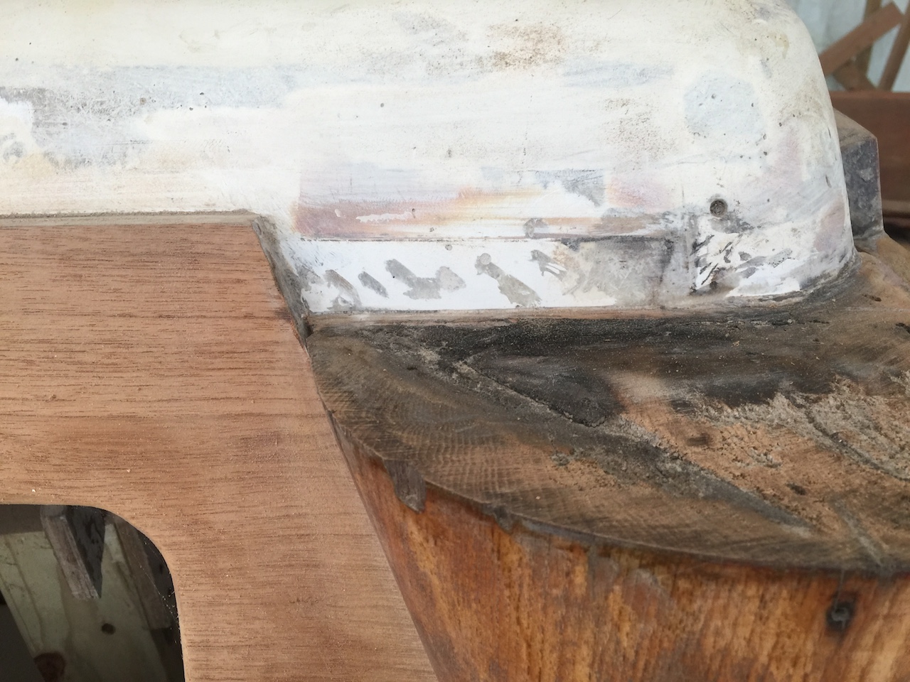
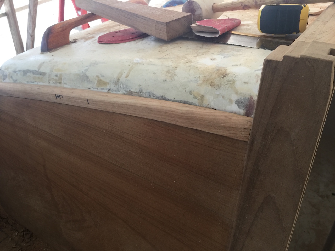
You can see the corner in the photo below and also that I’ve cut a slice out of the mating piece.
I matched the mating piece to the cabin top by gluing up an extra bit to the mating piece.
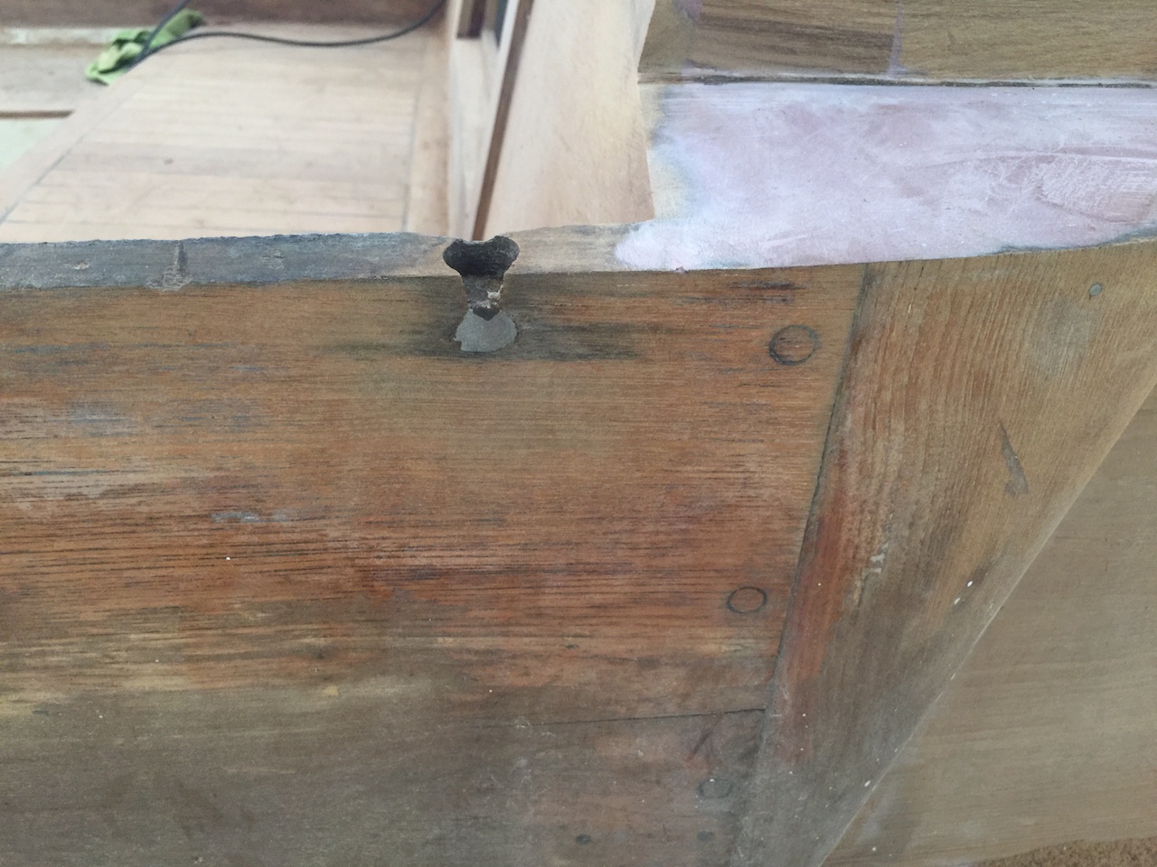
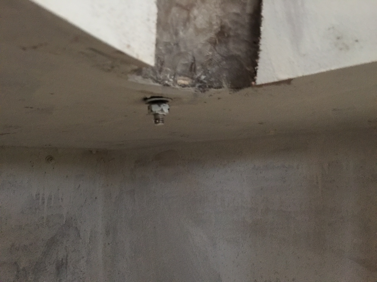
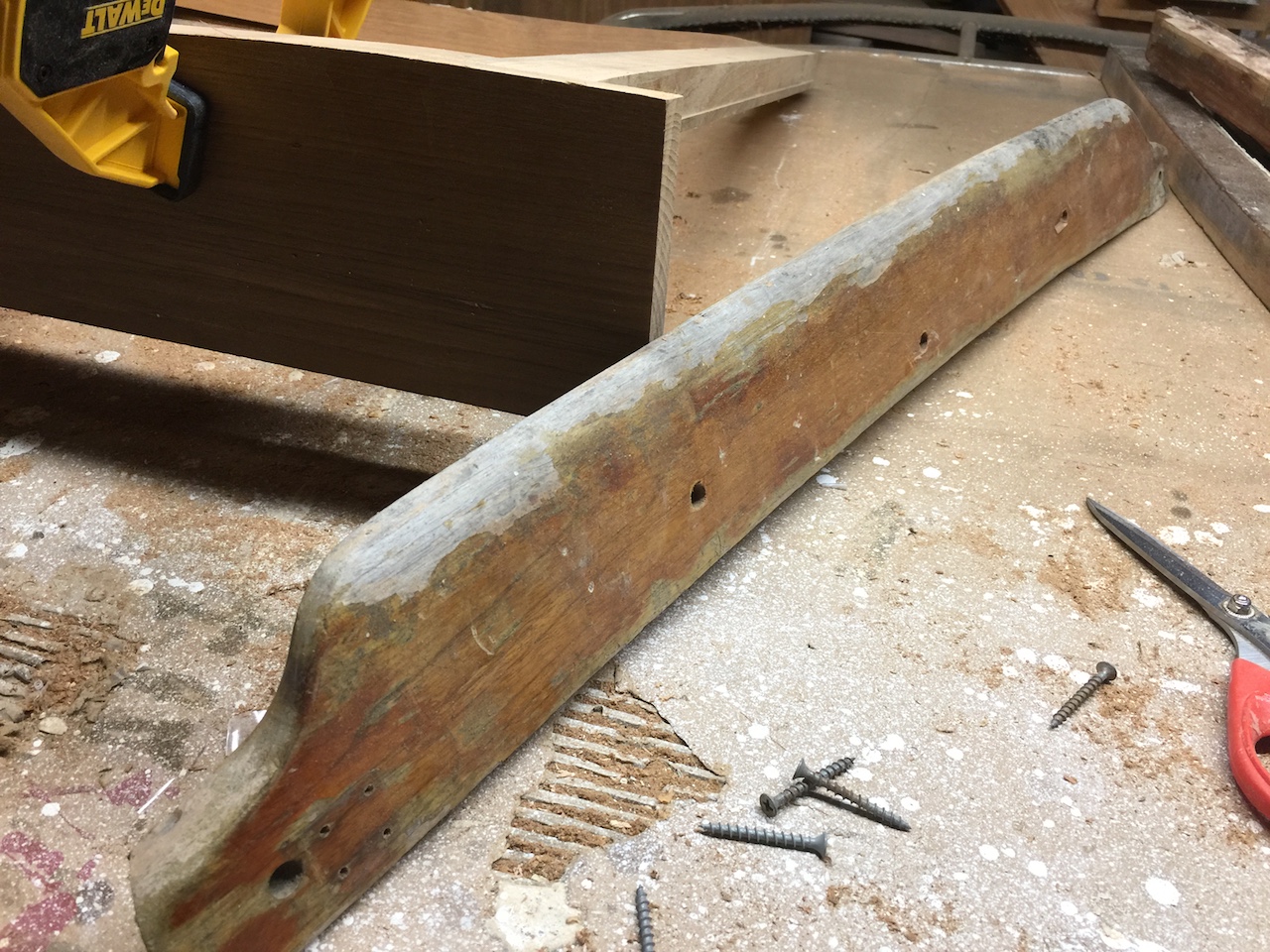
Before proceeding too far, I had to address a problem in the coaming. The coaming is attached to the cockpit with a number of so-called drift bolts. One of the plugs has failed and fallen out, and the original plug hole breaks through the side. You can see where it’s been “patched” with something.
I cut out the wood surrounding the top of the bolt, which left the exposed bolt head a little high (not shown).
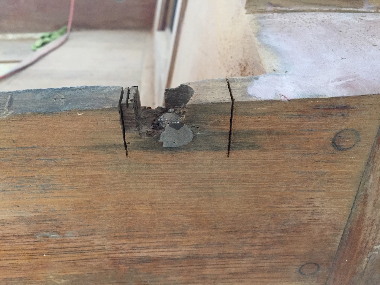
I hammered down on the bolt to seat it properly, but found that there wasn’t sufficient threading on the bottom end to be able to tighten the nut.
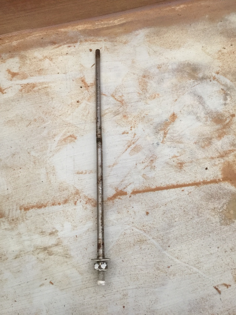
So I just cut off the top and drive it through with an old screwdriver. The bolt, pictured below, is 14″ in length and in fine condition.
I considered replacing the drift bolt, but decided instead I will (eventually) install a long lag bolt upward, from underneath. Thus, I was free to patch up the hole.
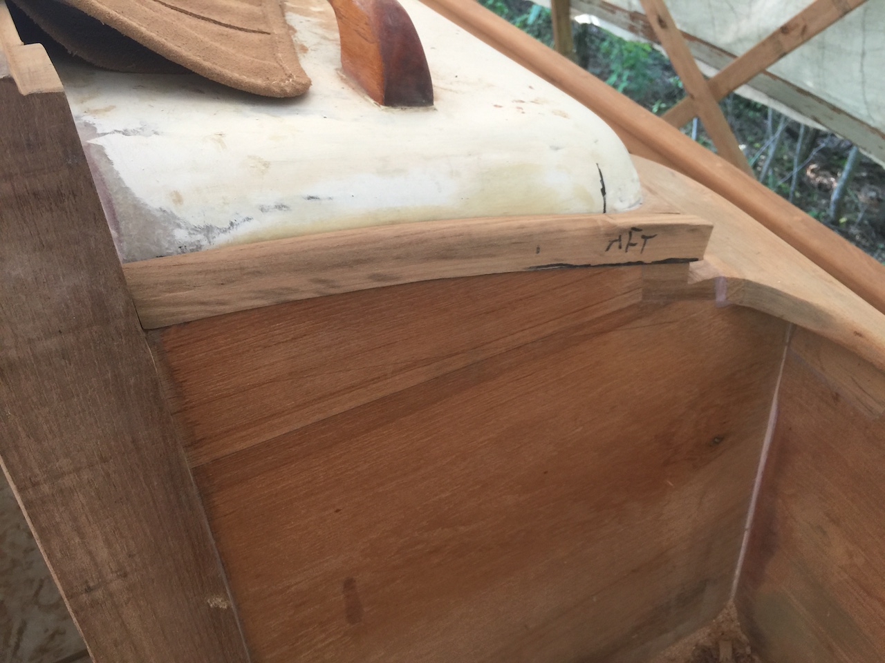
The pencil line on the mating piece was used as a guide for adjusting the mating piece so that it mates properly.
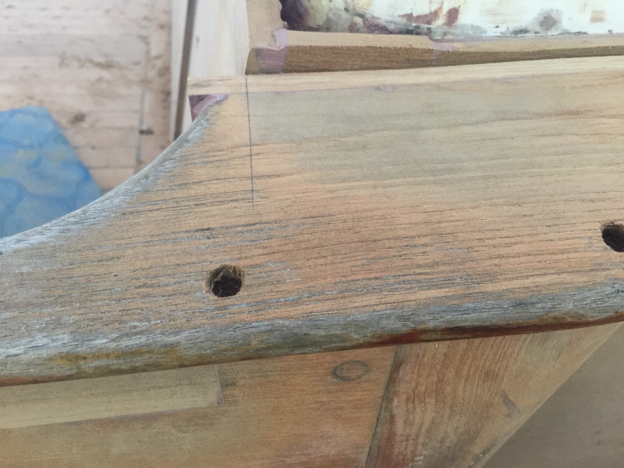
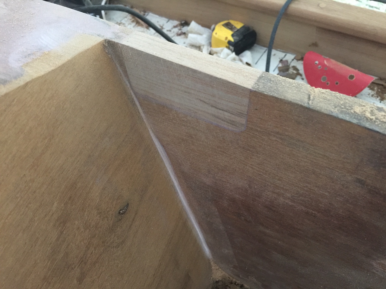
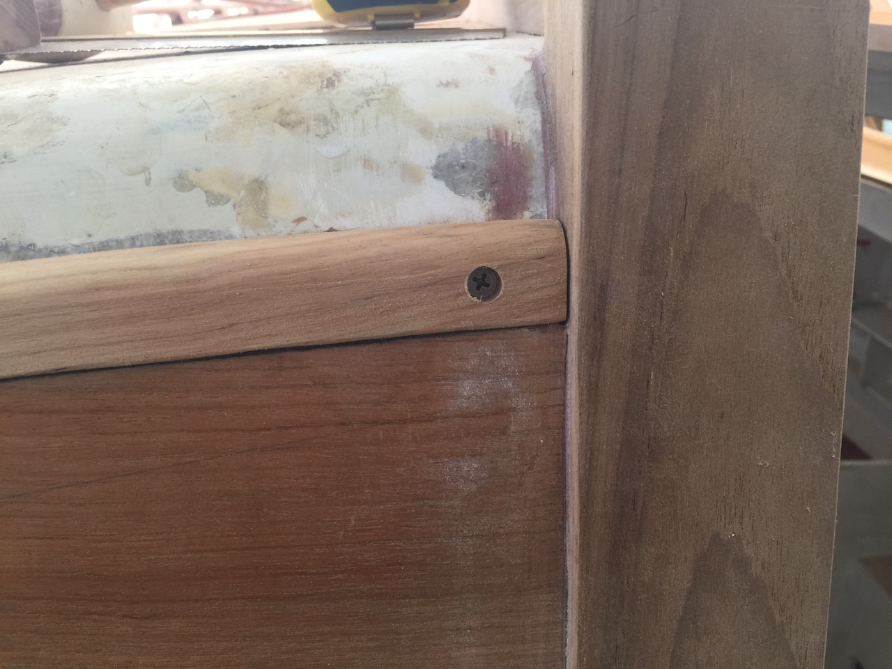
I used a larger diameter countersink bit in the final installation, and you can see the sanded plugs in the photo below.
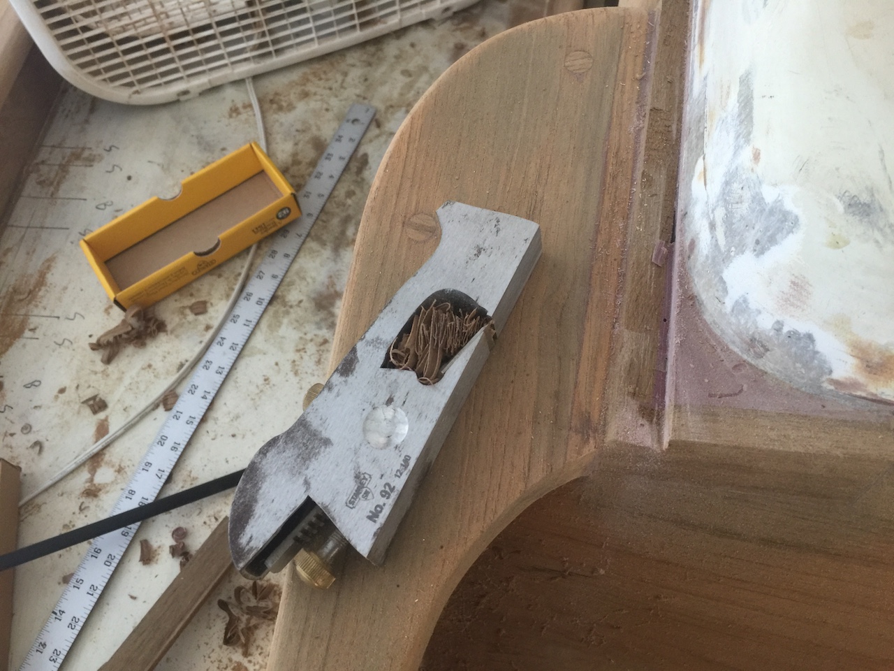
The rabbet plane helped with working the edges.
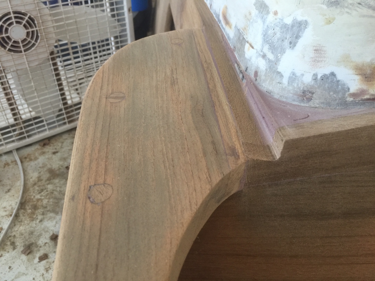
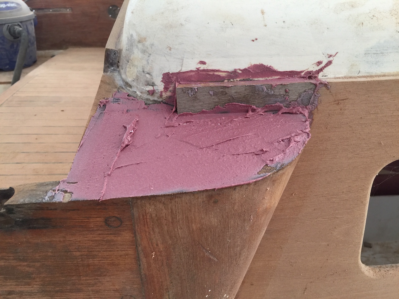
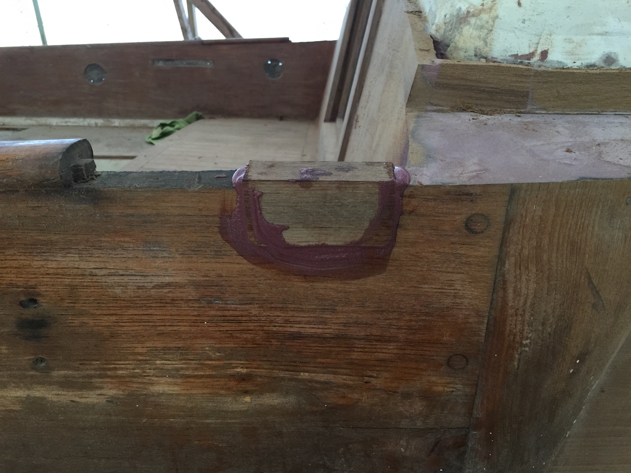
You can see from the last two photos I that I filled the corner with thickened epoxy, and now I had to round the corner. I didn’t use patterns this time, but was still able to get good-fitting pieces. These were glued into place (not shown).
The aft side of the corner will be defined by the drip molding in the cockpit. Normally, drip molding might be bent into place, but the curves in the cockpit were a bit severe, so I made patterns and cut the curves.
After some sanding and shaping, the pieces fit pretty well. Here is the port side:
And here is the shorter starboard side:
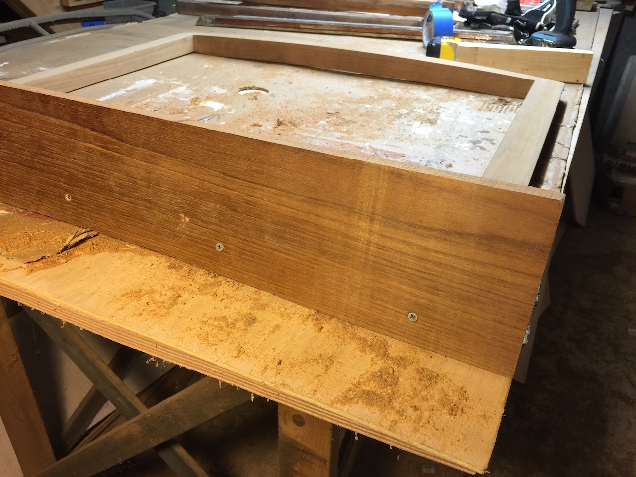
Clamping these pieces would be difficult, so I decided, instead, to use countersunk machine screws and screw the pieces into the fiberglass, which was the original system anyway.
For final installation, I bedded with epoxy and plugged the holes.
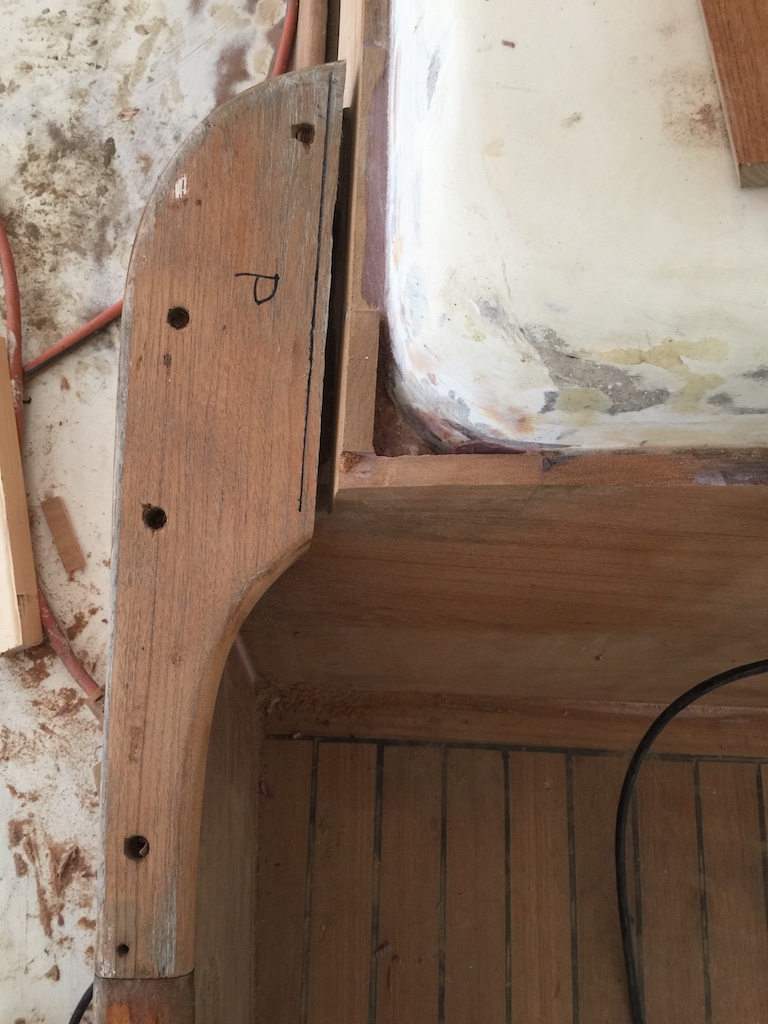
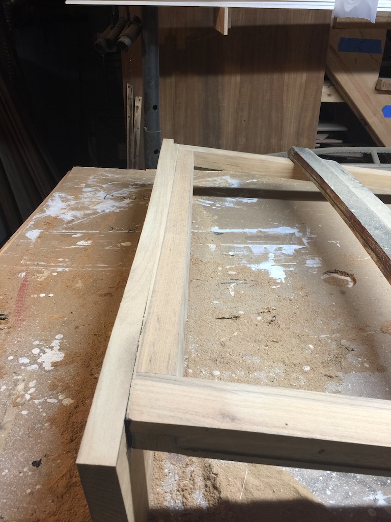
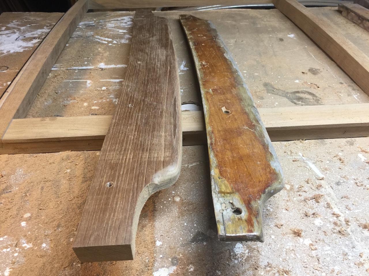
Meanwhile, a rainy day provided a good opportunity to continue working on the companionway hatch in the workshop. The photo below shows the original piece that defined the aft edge of the hatch. It’s main purpose was as a handle for pushing/pulling the hatch open/closed.
I began by cutting a new blank and tracing the curve of the bottom edge. I shaped that edge, with the correct bevel and eventually screwed it into place temporarily.
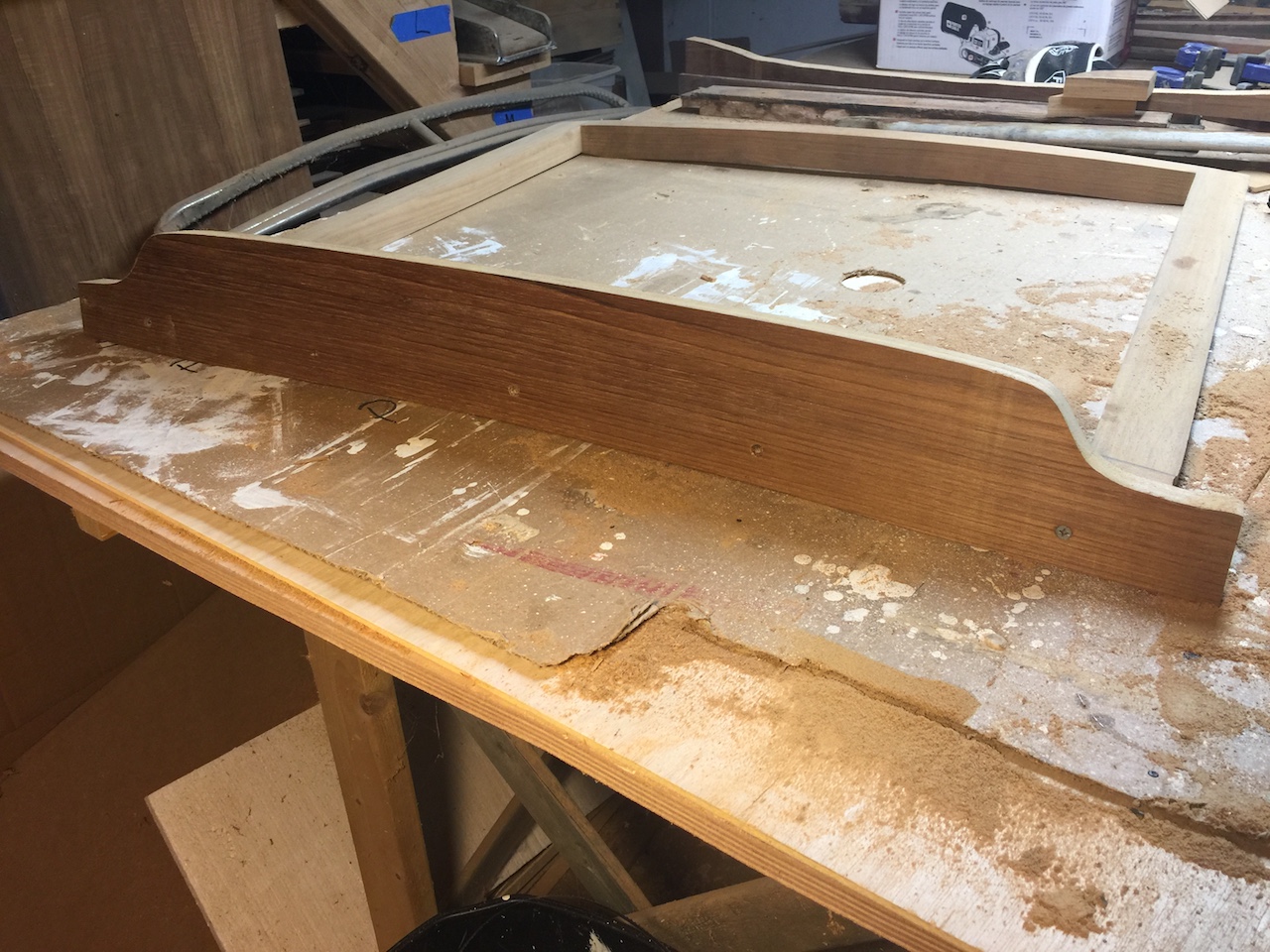
I finished matching everything up by sanding.
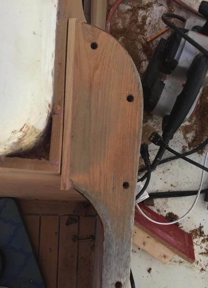
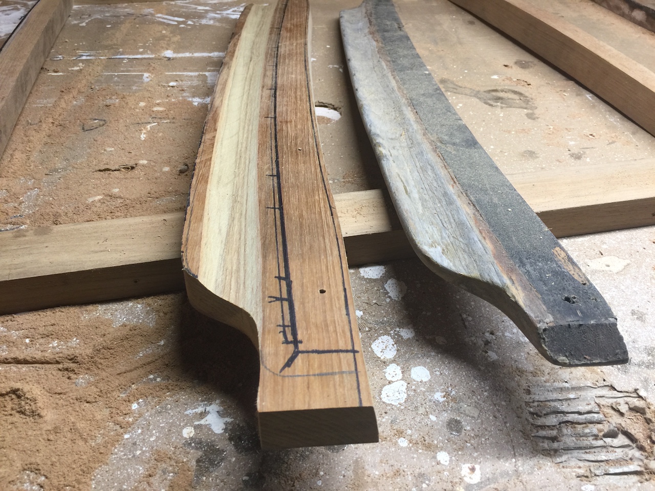
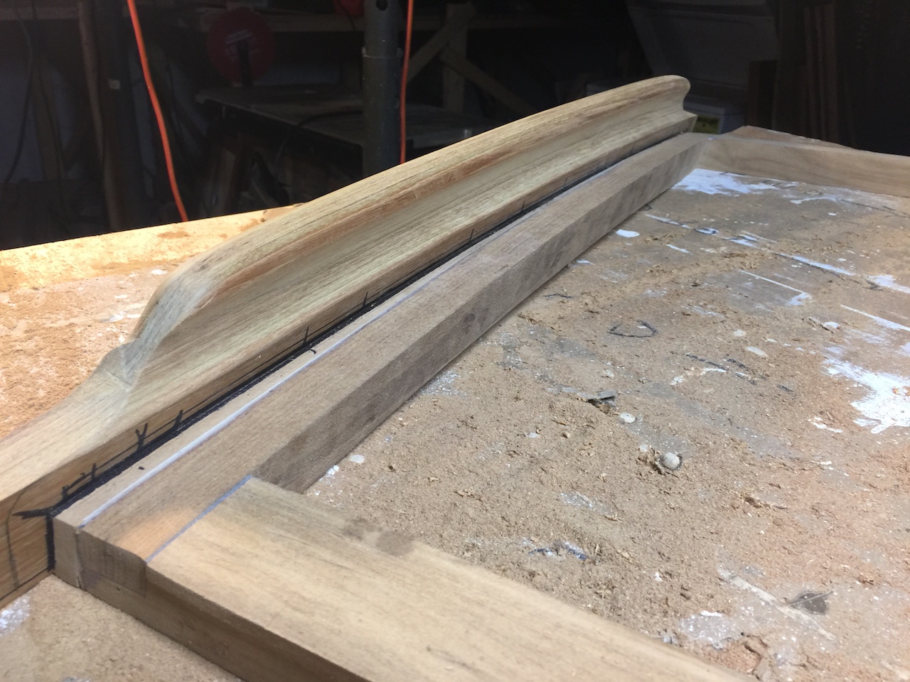
Tracing the top edge of the original piece and cutting with the band saw yielded the following.
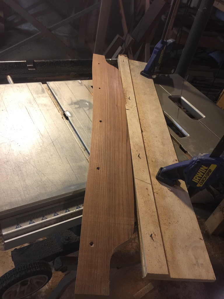
The forward side of the “handle” contains an ergonomic curve. I cut this curve in the same way I cut the inside surface of the corner pieces. This curve, however, had to follow the curvature of the top edge, so I had to be careful to keep the piece aligned properly as I ran the piece along the temporary fence.
After some routing and sanding, it looks pretty good.
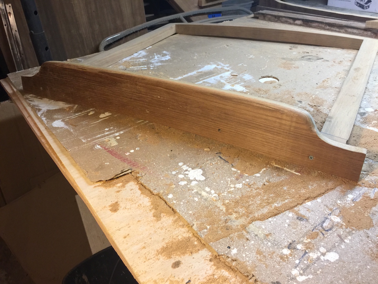
There’s still a lot to do here, but further work on this piece requires some decisions on other aspects of the hatch.