8/30/18: Mast Step, Dorade, Samson Post, Handrails, Etc.
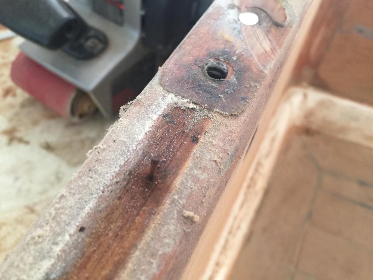
In the cockpit I removed the mainsheet track.
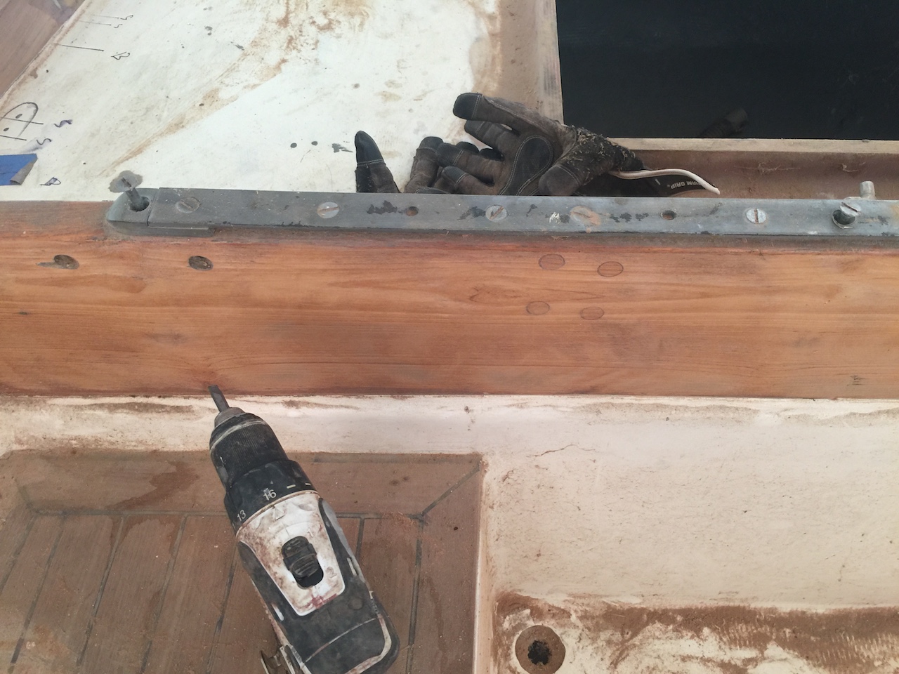
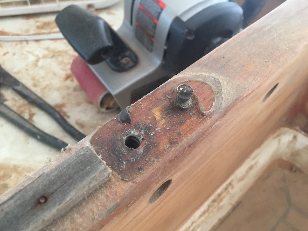
One of the screws broke off, but this is no problem. I ground it down, and I’ll simply reinstall the track a few centimeters one way or the other. Making sure new screws are sunk into fresh wood (instead of reusing existing holes) is good practice anyway.
The teak strip that separated the top of the coaming with the rail was secured with not-stainless brads, as you can see here.
The original fastenings are somewhat cheap and I’ll be glad to have replaced them.
Way back in Summer 2012 I laid new teak in the cockpit and build new cockpit locker hatches. Part of closing up the boat should be installing these hatches, and I’ve done so using external stainless hinges and screws. Eventually (when I’m sure I won’t have to remove the hatches again) I will through-bolt the hinges.
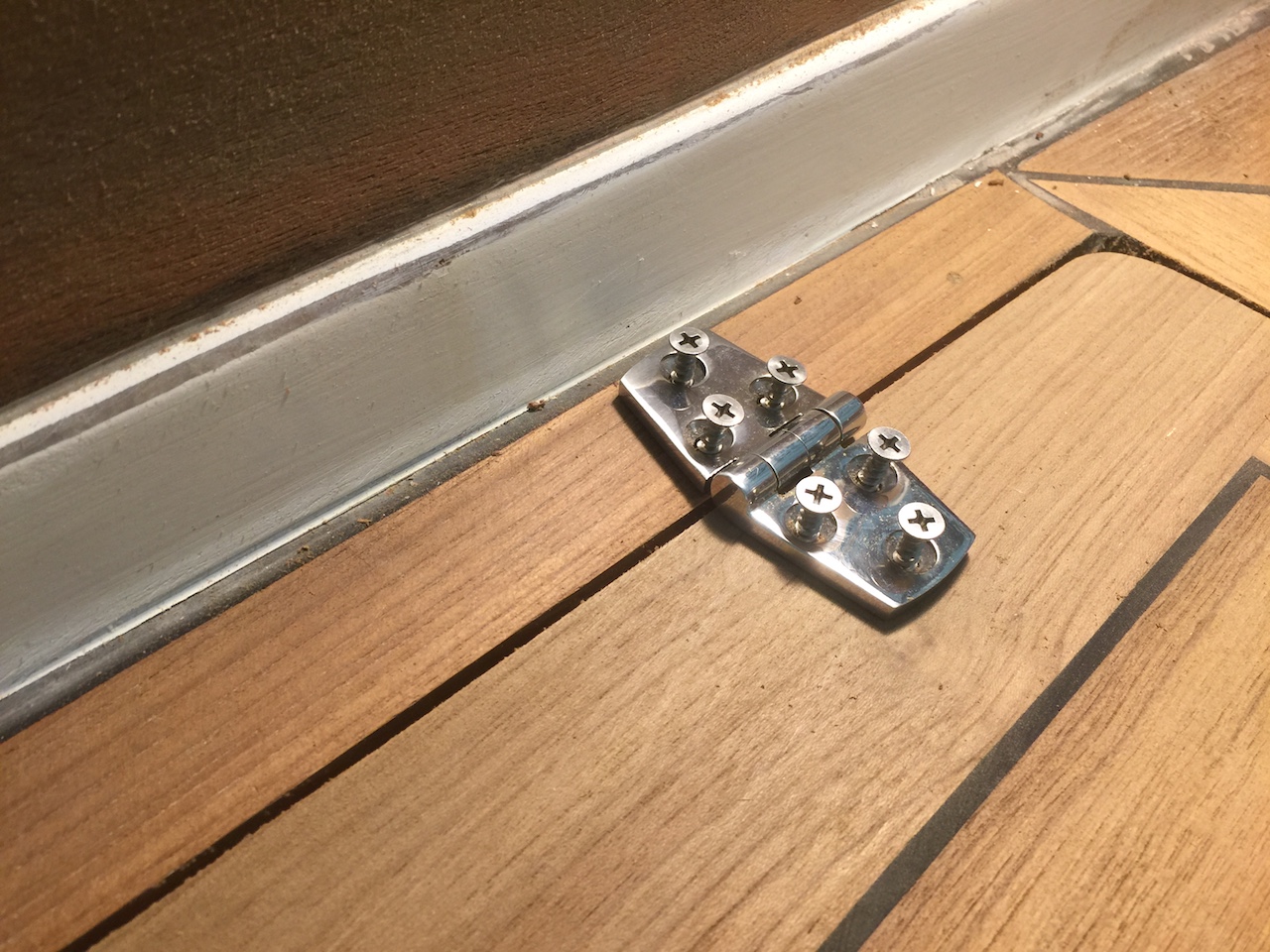
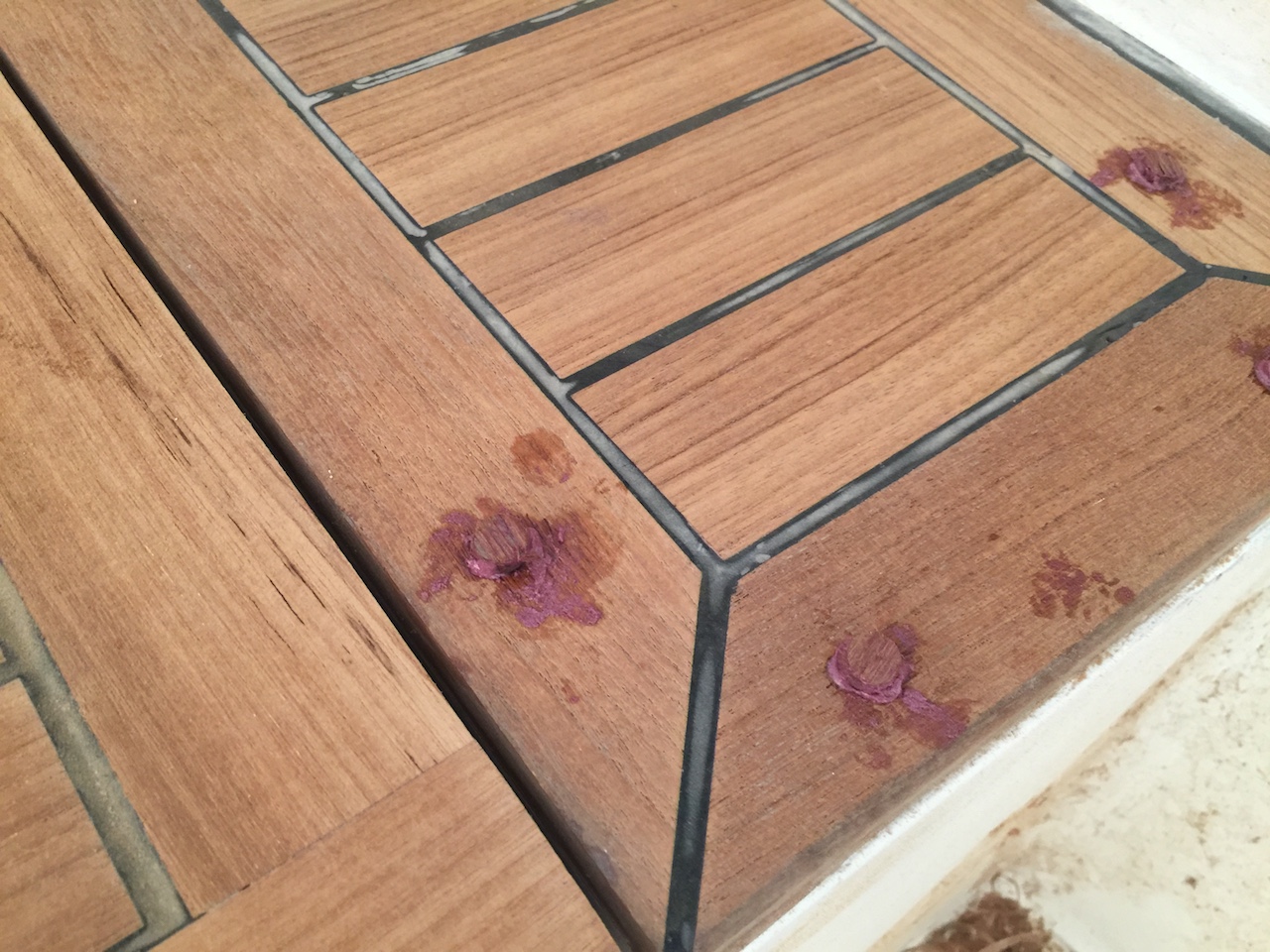
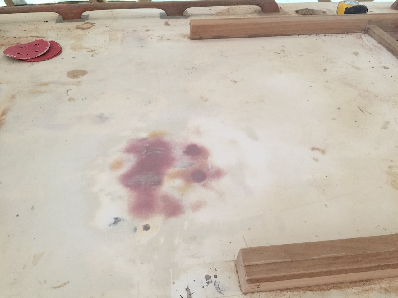
If you look carefully at the photo above you can see a screw hole in one of the perimeter boards. I’ve circled it in red in the photo below.
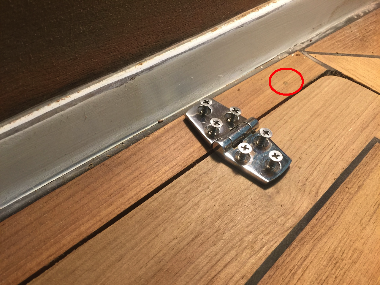
All of the cockpit teak was set in epoxy and held down with temporary screws. I had to drill through the perimeter boards, and finally I got around to plugging those holes. I made plugs (bings) from scrap teak, and here I’m beveling the edges to make them easier to insert.
I set the plugs in epoxy and eventually sanded then flush (not shown here).
I continued working on the companionway hatch by installing the horizontal, athwartship piece of teak in the photo below. This hatch will be mostly covered by the spray hood (more on that later), and the space you see here is simply dead space that the hatch moves over as it slides in and out.
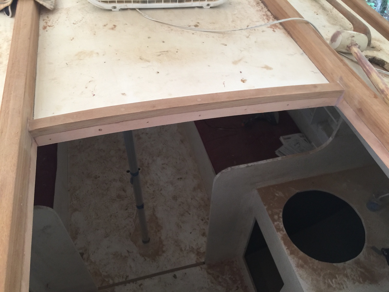
Water can collect here, so limber holes are necessary. These would have been much easier to create before installing the rails, but they are necessary, so…
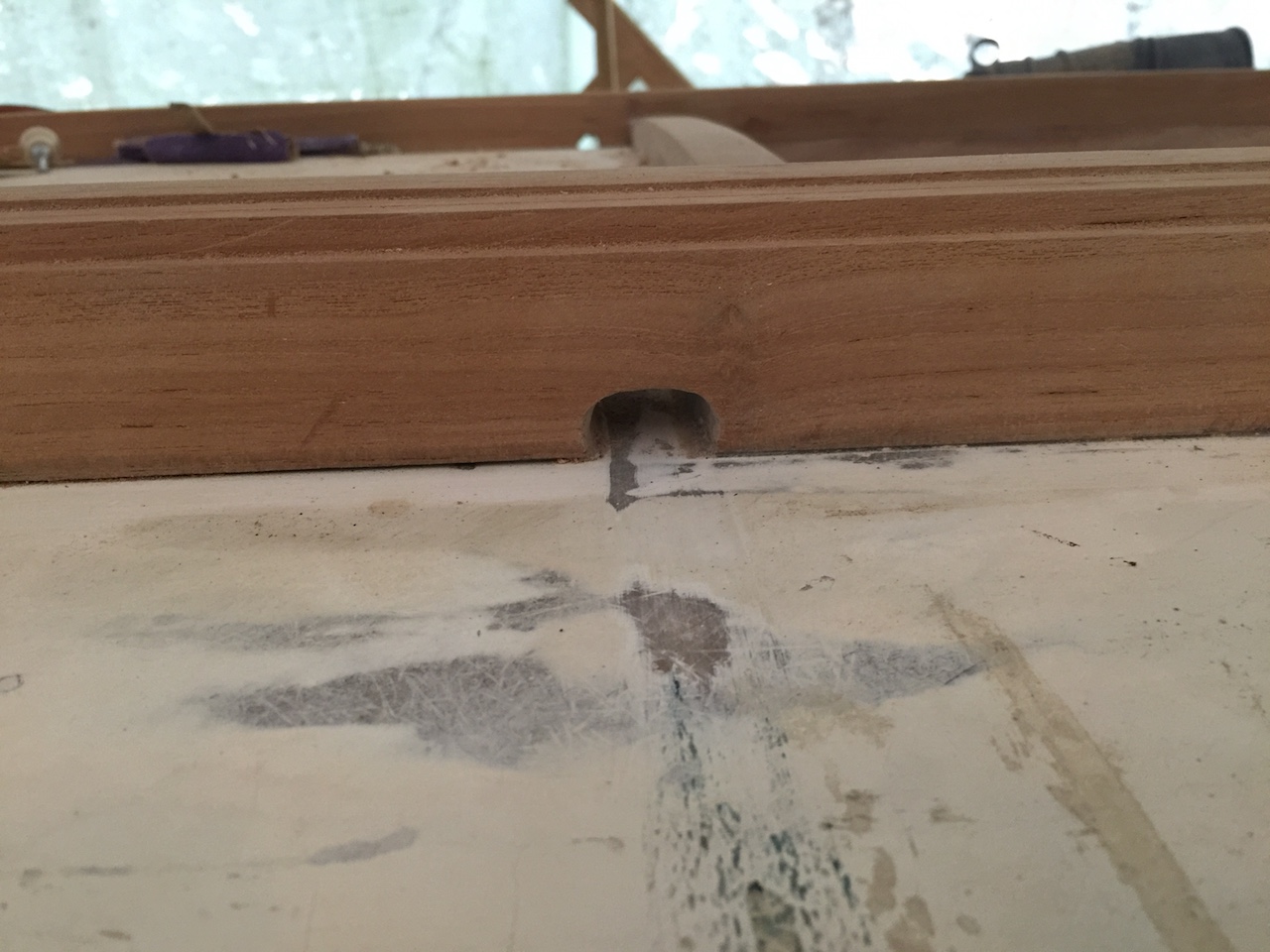
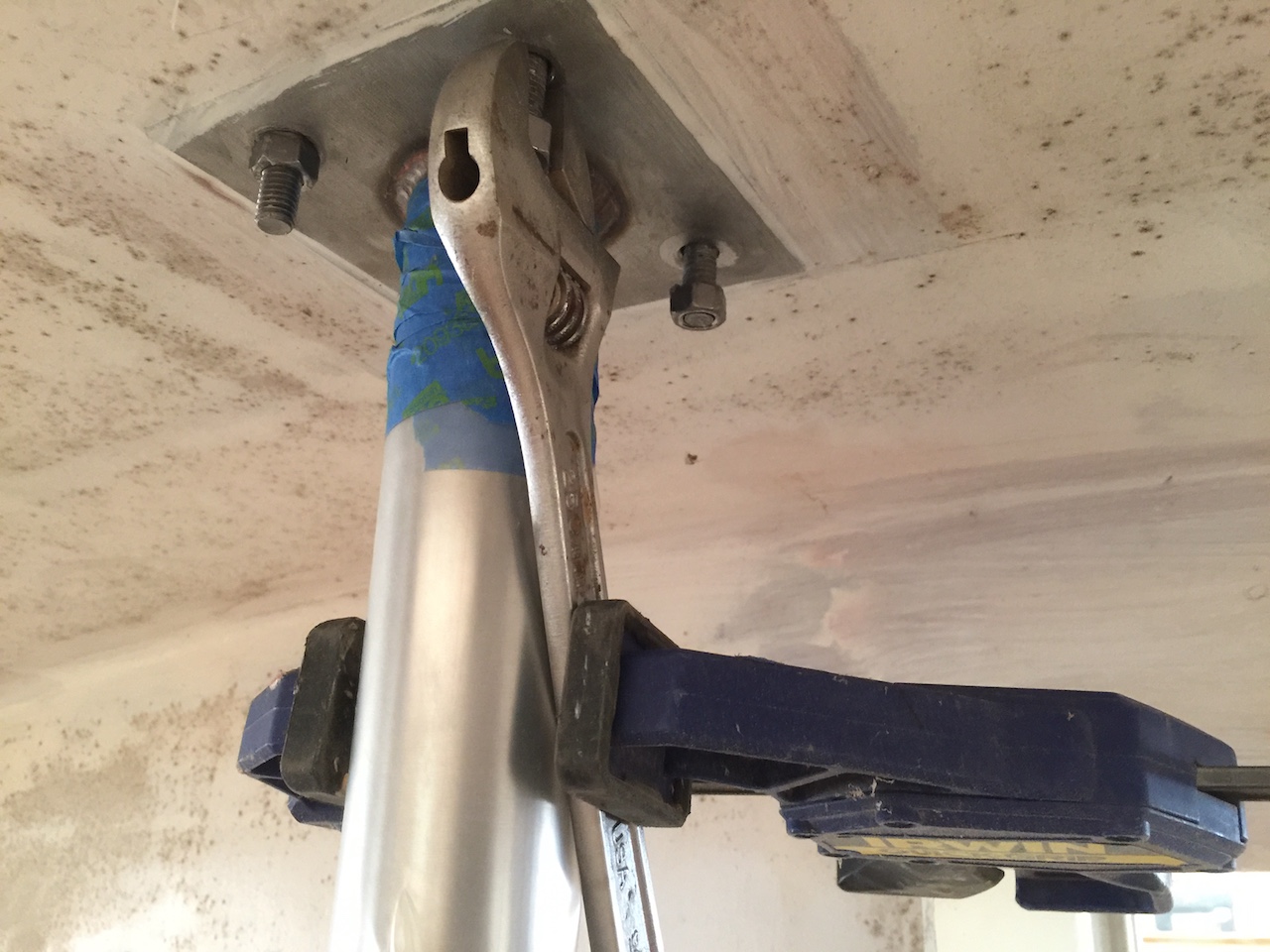
The “dead space” I just spoke about is over the aft-most of the three compression posts.
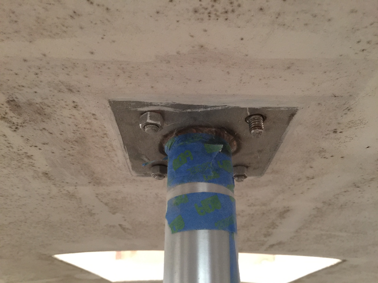
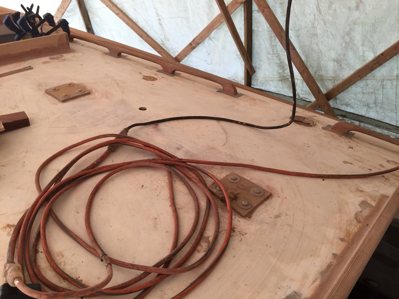
The compression posts were installed back in 2014, and I used temporary bolts and plywood pads to secure the top ends. You can see these pads and bolts in the following two photos. Here is the dead space:
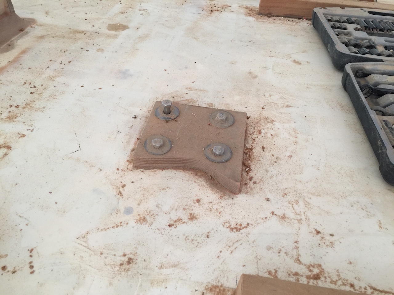
This is above the forward and middle compression posts (left and right in the photo, respectively).
The bolts for the aft compression post are completely hidden in countersinks in the fiberglass.
The installation is permanent.
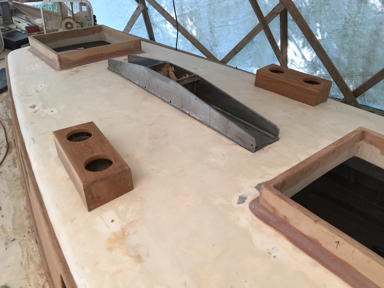
The mast step is bolted to the forward and middle compression posts, and here is the mast step:
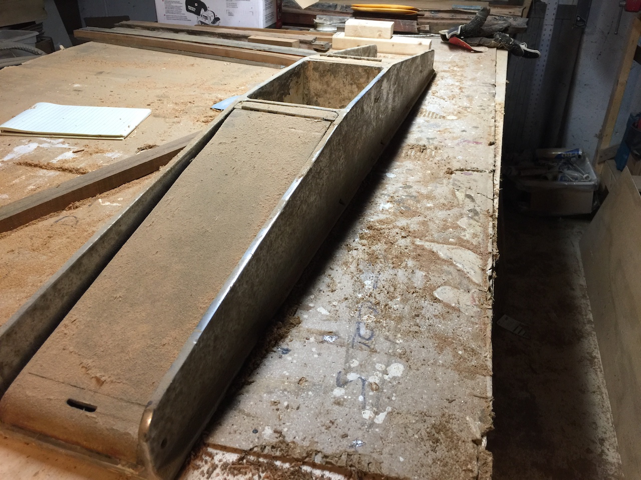
The mast is stepped on deck, and this 80-lb piece of stainless steel transfers the downward forces due to the mast onto the compression posts.
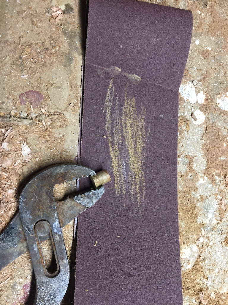
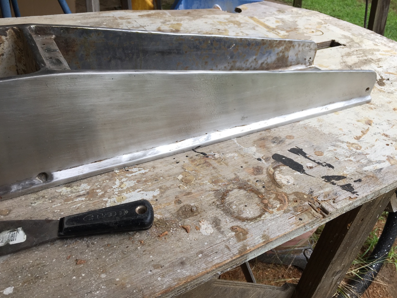
Here is the part in which the bottom of the mast sits.
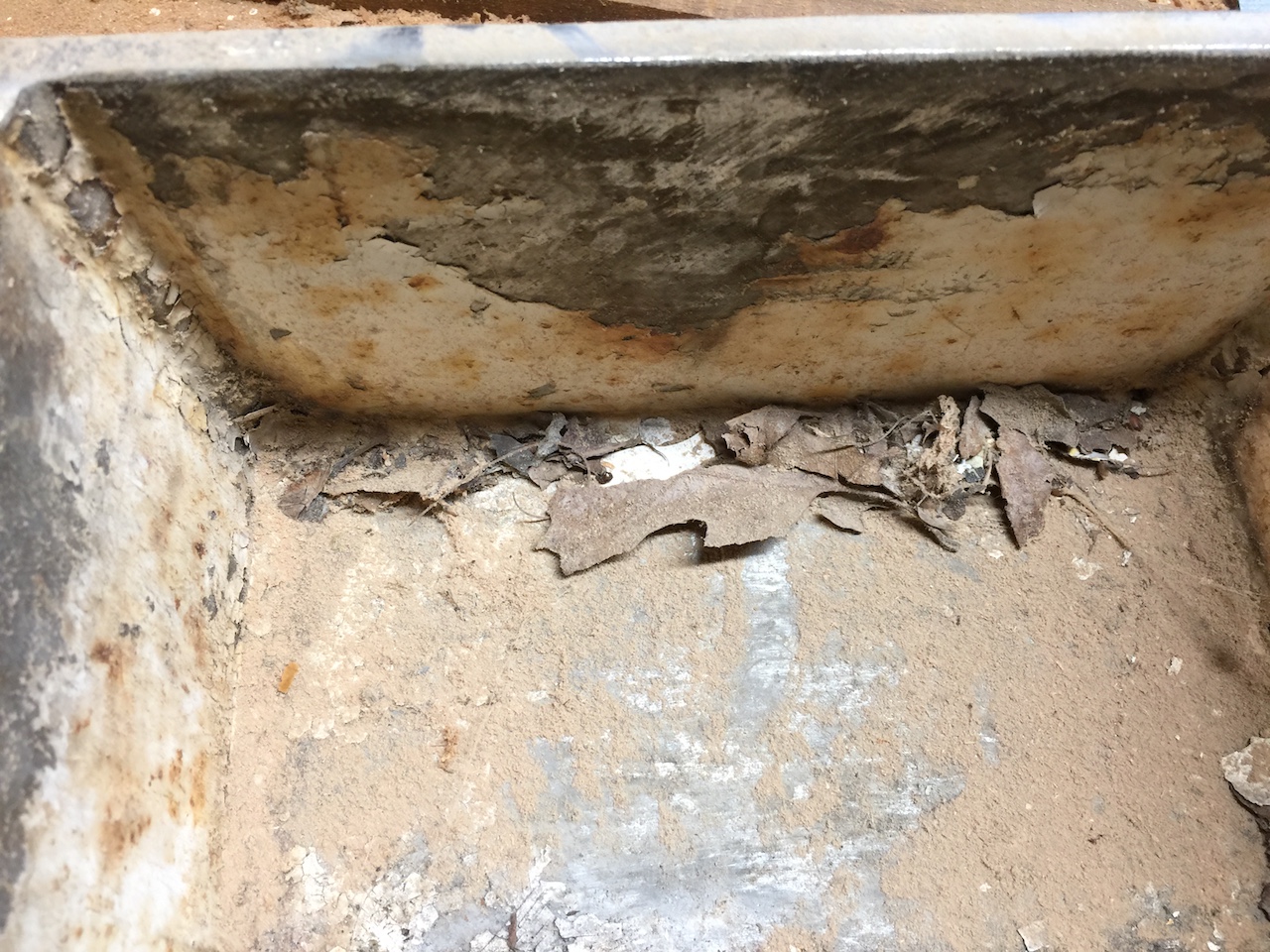
I was able to clean up the exterior using 180-grit sandpaper.
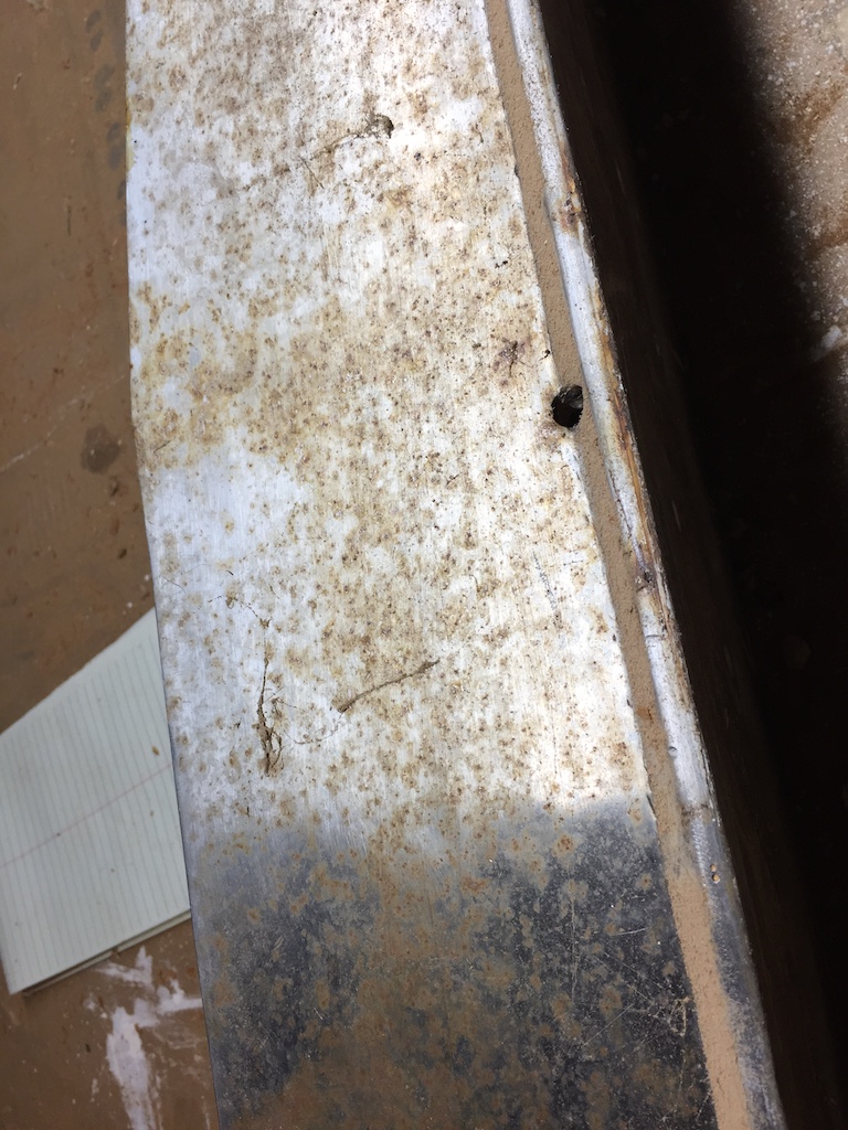
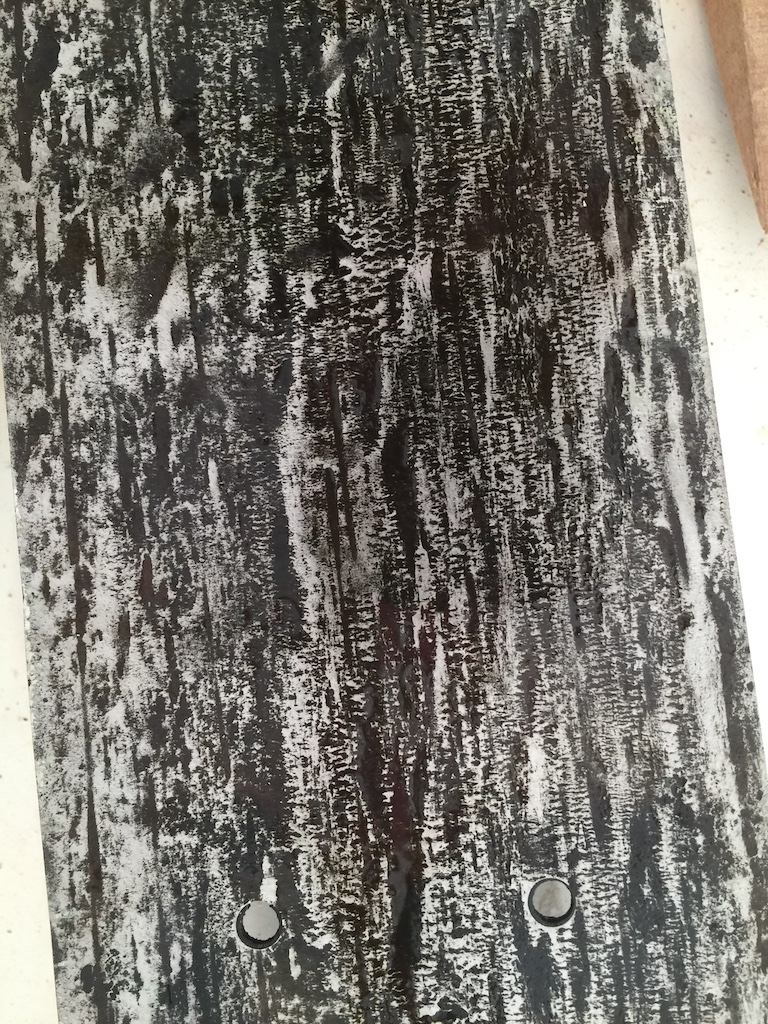
Flipping it over, we can see the bottom, which has some black sealant and a little surface rust.
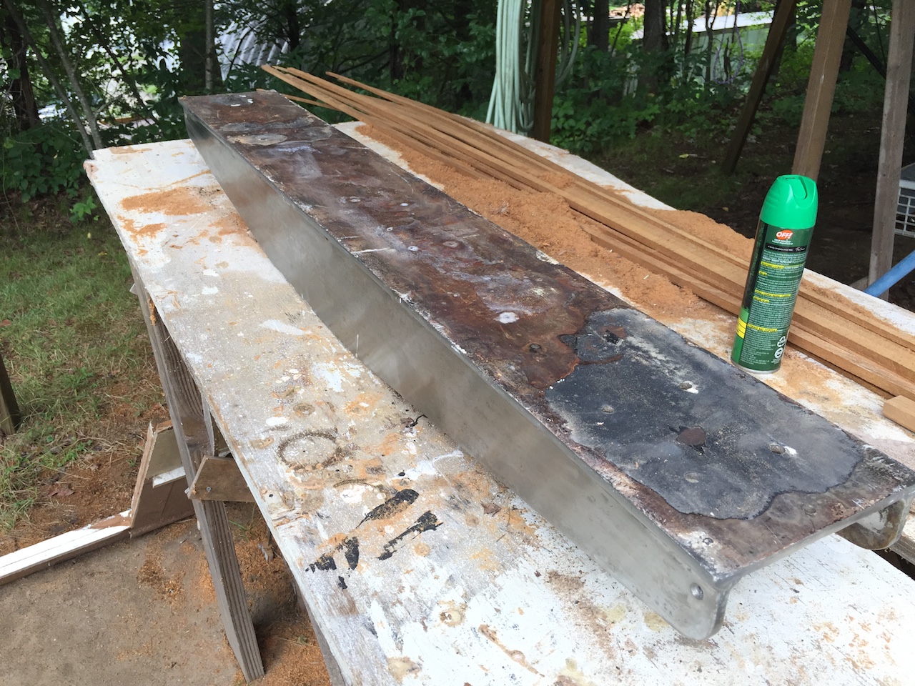
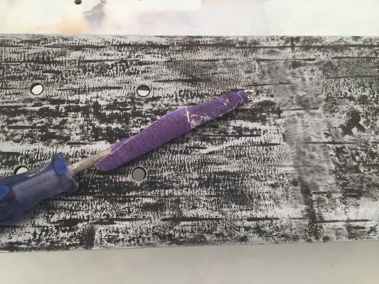
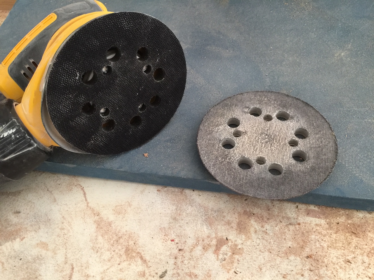
I used the disc sander to clean up the bottom.
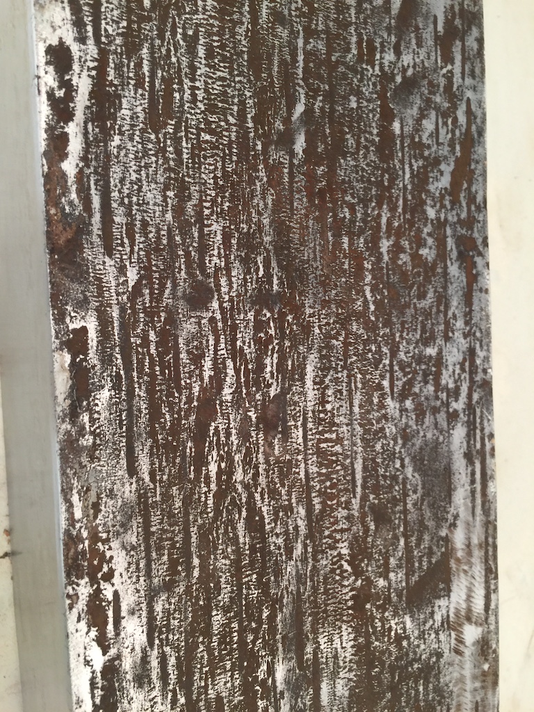
I used a liquid product called OSPHO, which neutralizes the rust by changing its chemical composition.
The rubbery, black sealant had to be cleaned out from the bolt holes.
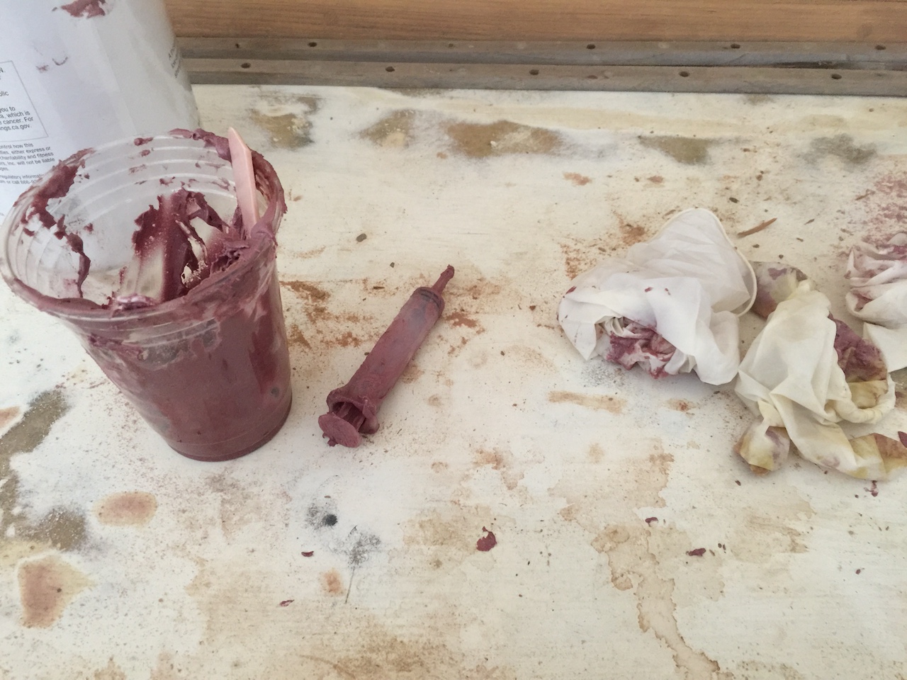
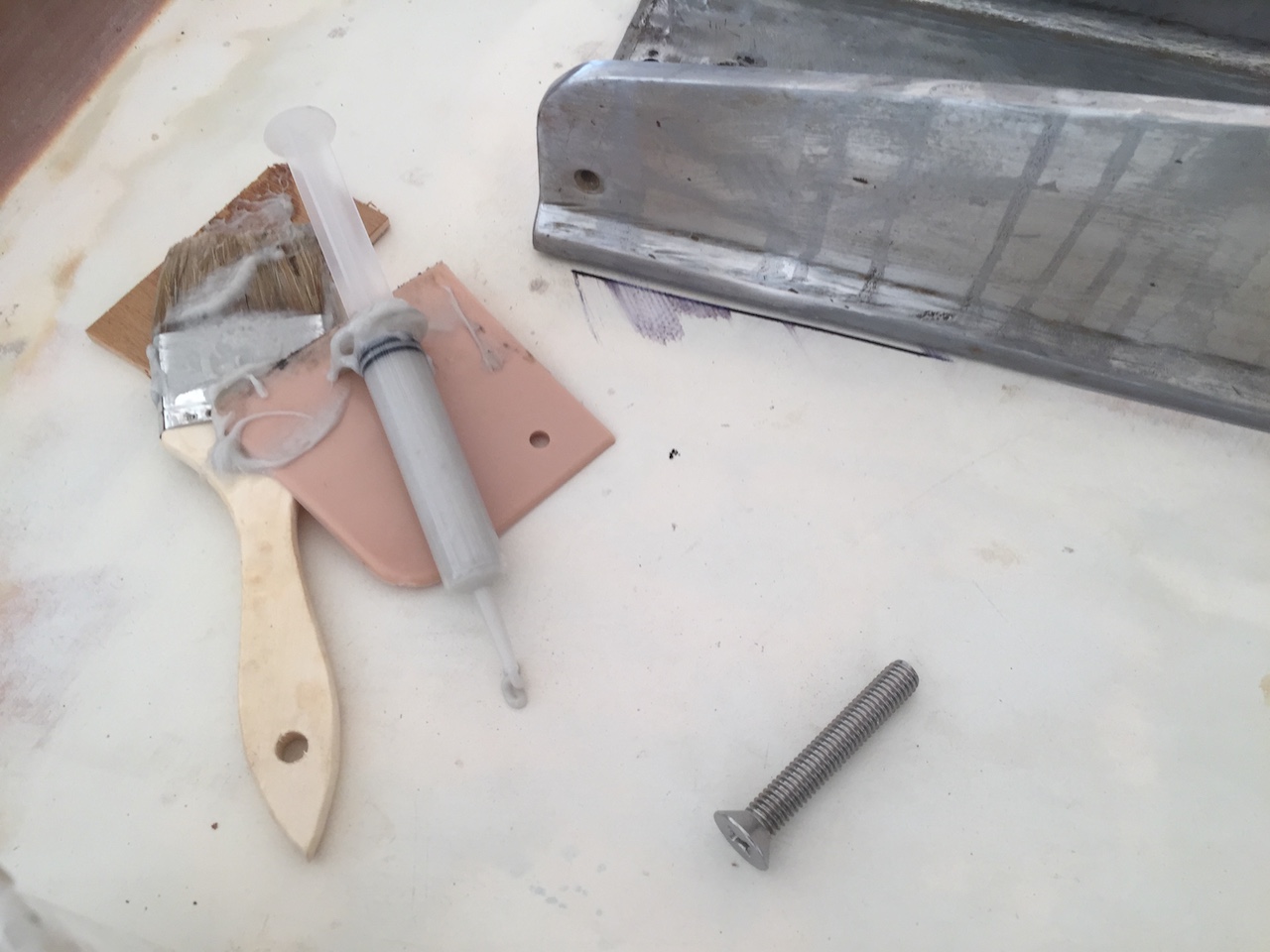
I set the mast step in thickened epoxy, and tightened the eight bolts.
There was no squeeze-out in a few places, so I injected more epoxy using a disposable syringe (a West System product). I used high-density filler to thicken the epoxy, rather than the low-density stuff I use for filling and fairing.
Next, I addressed the four ventilation holes in the roof, which operate by the usual cowl-vent/dorade-box system. I replaced the four dorade boxes back in 2012, and here is one of them.
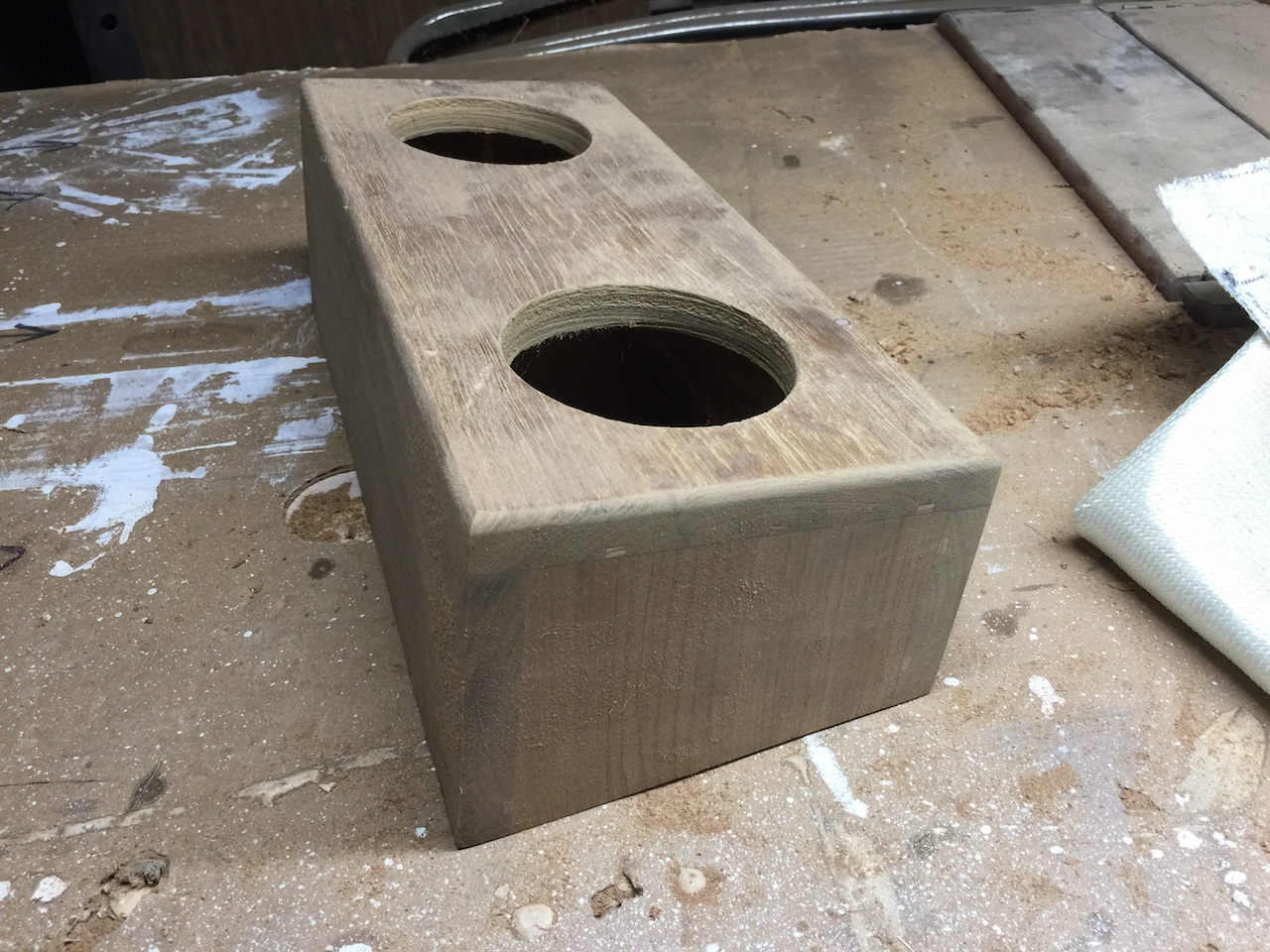
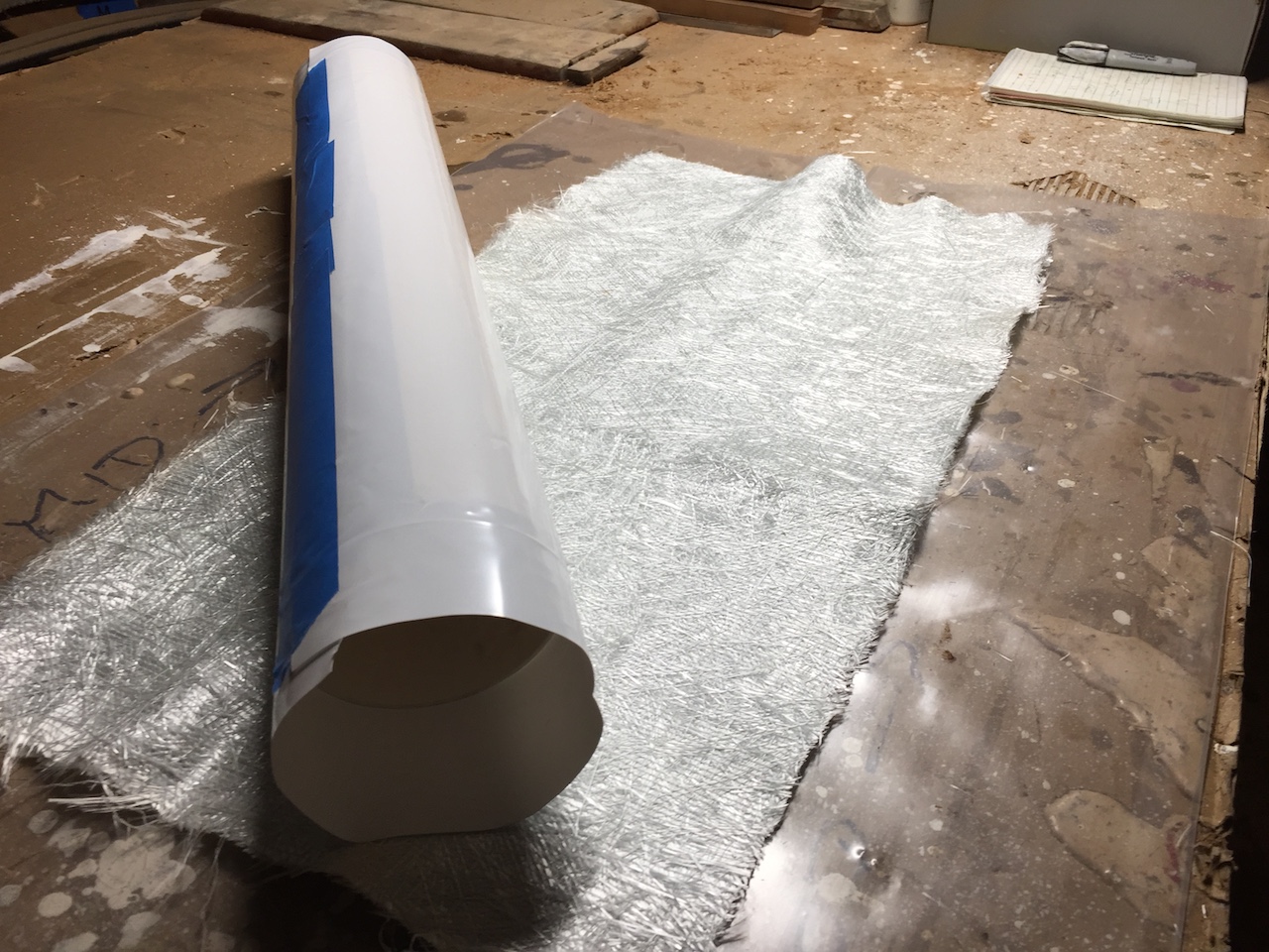
One of the holes will be over the hole in the roof, and will have a cap, while on the other hole will be the cowl vent. The hole in the roof must have a tube protruding above the roof to keep water out. I made these four short tubes from fiberglass. (Previously I had used PVC pipe, but the fiberglass tubes will be better.)
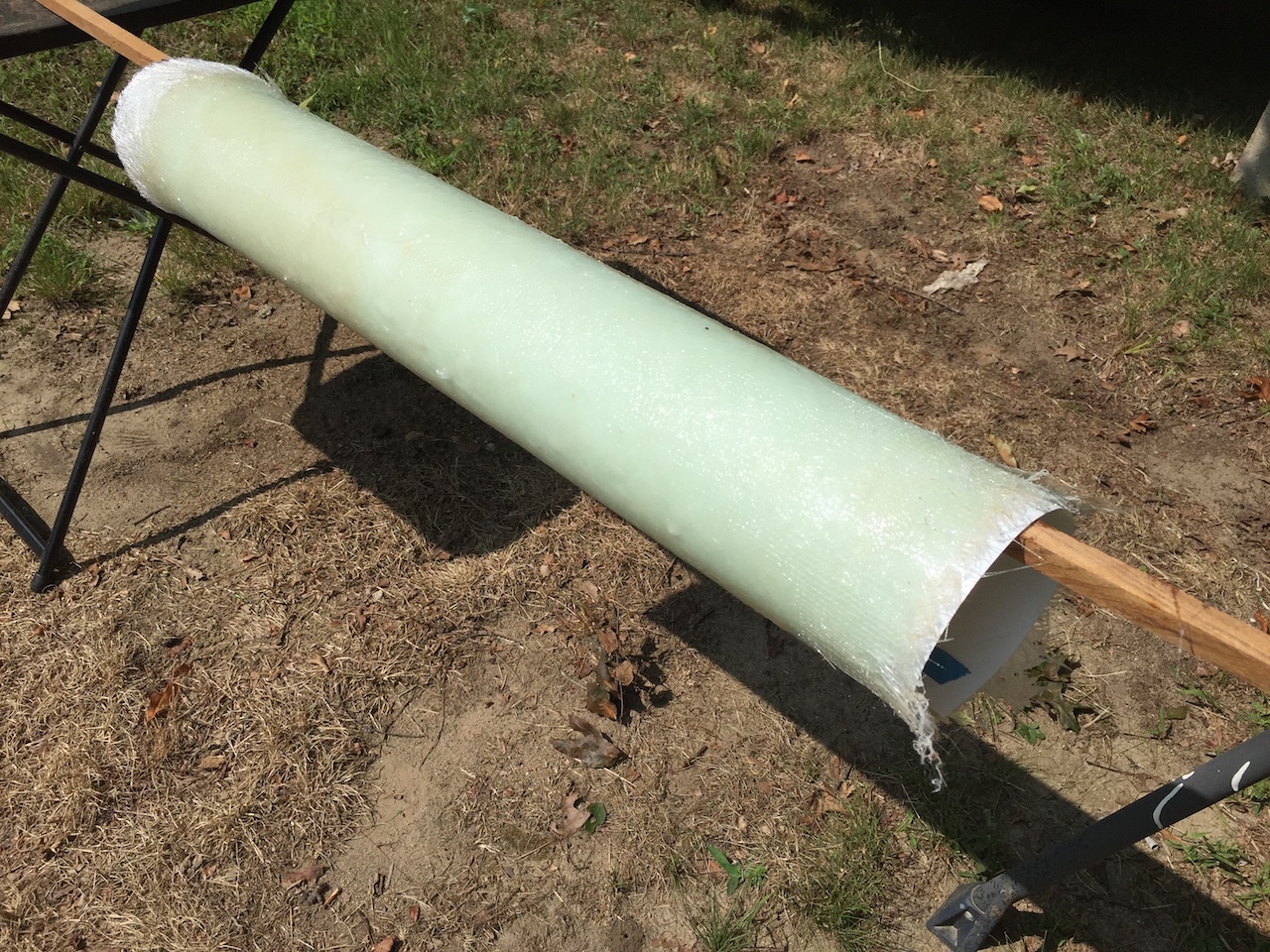
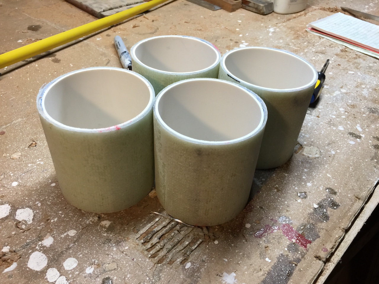
After the epoxy cured, I used the chop saw (and an old blade) to cut four pieces to the correct length. I removed the PVC mold and installed these on deck.
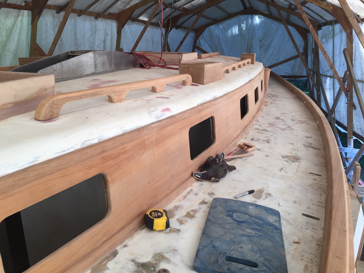
You’ll see one in a picture later on, but here I’ve placed the dorade boxes on deck just to see how things look.
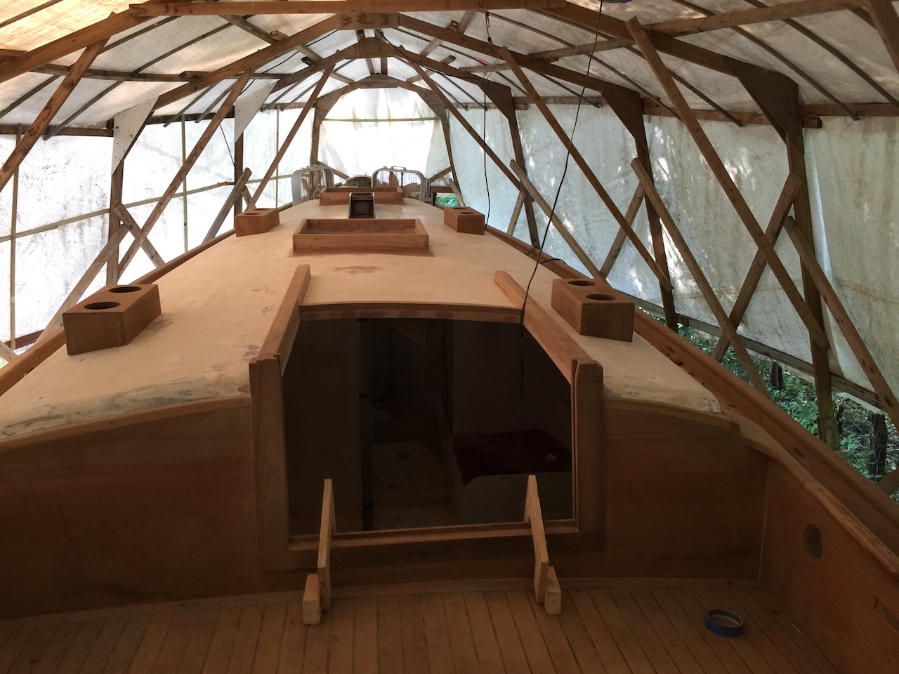
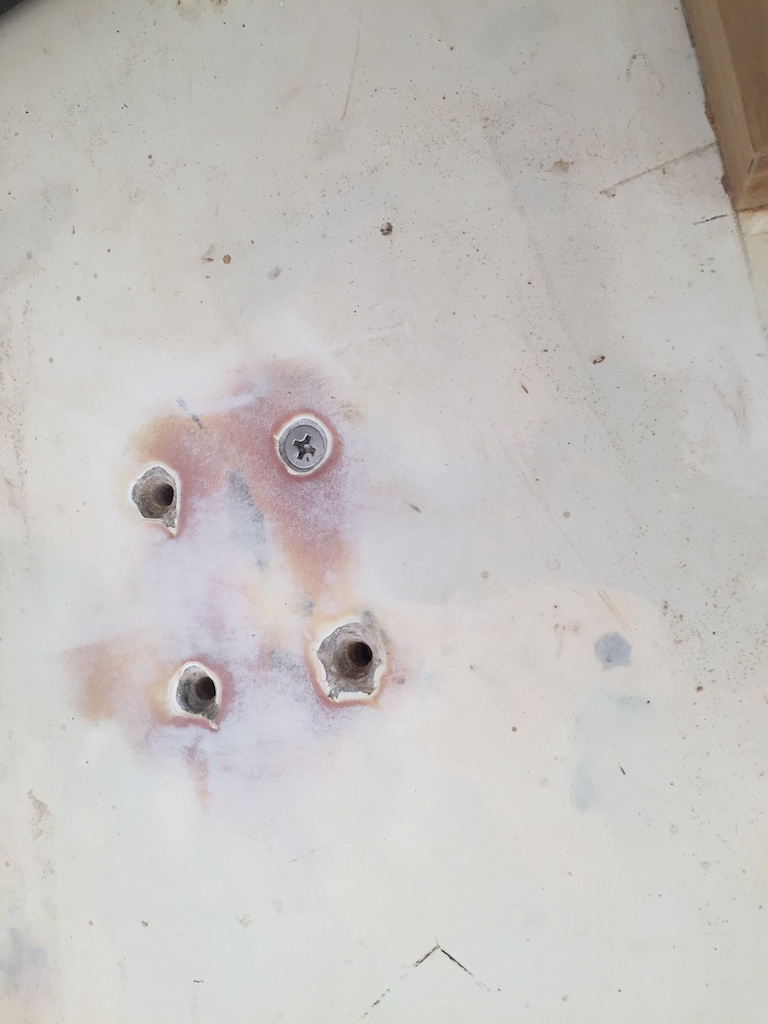
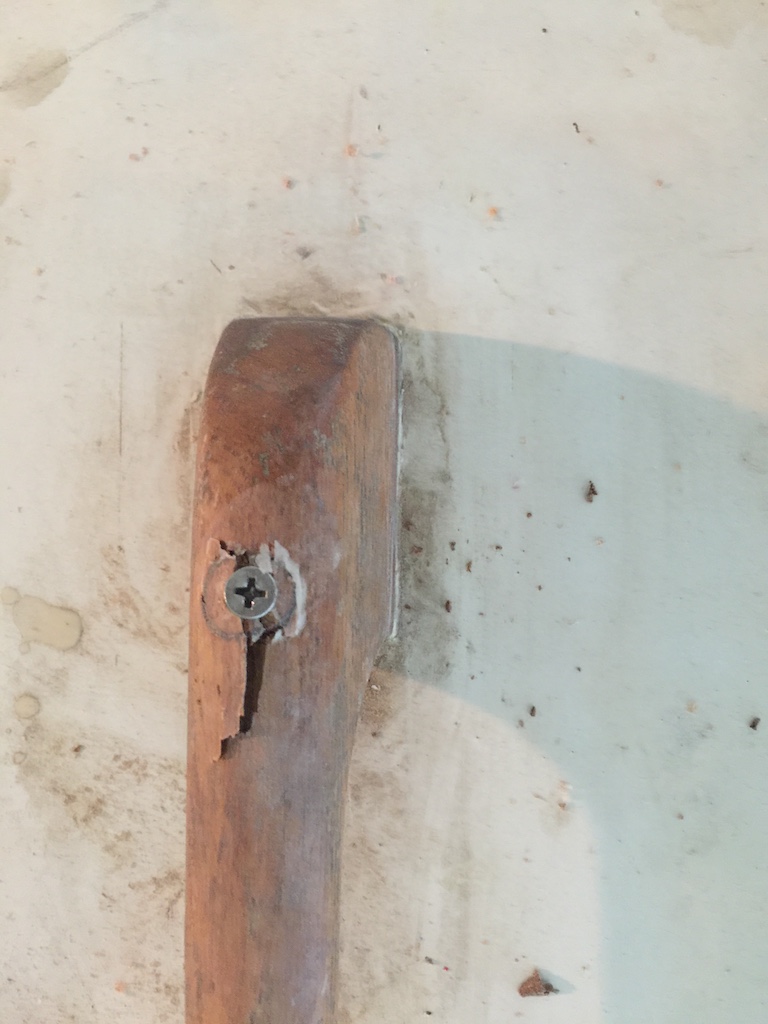
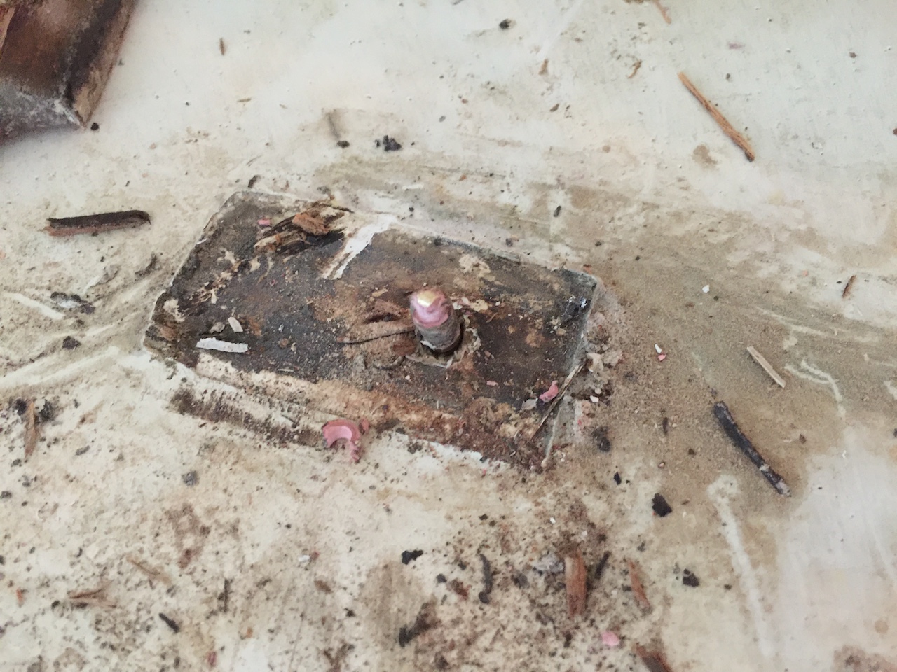
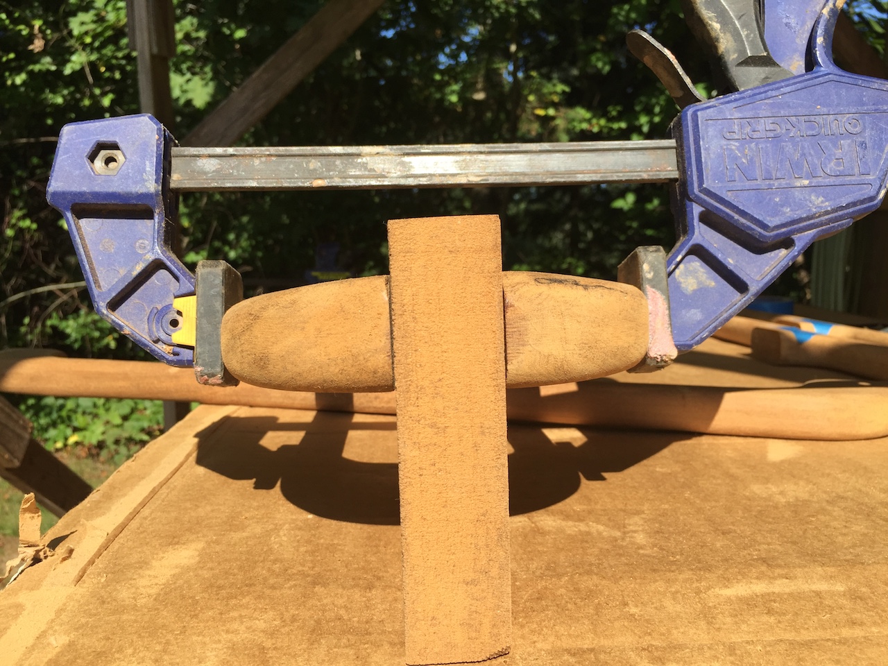
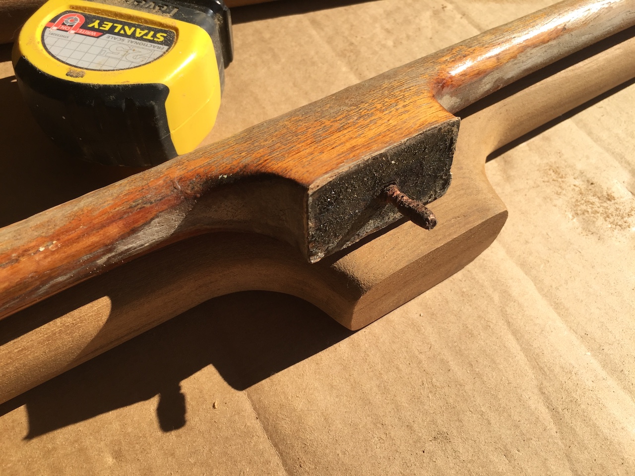
You might notice the lack of handrails in the previous two pictures. After some deliberation, I decided to remove the handrails. I had little hope of removing them without irreparably damaging them, but I tried anyway, and failed. Here I have inserted a small screw into a bung. In theory, the screw threads downward, and when it hits the fastening it lifts the bung. All that actually happened, but more then just the bung lifted up.
Banging them off with a hammer completed the job of removing them.
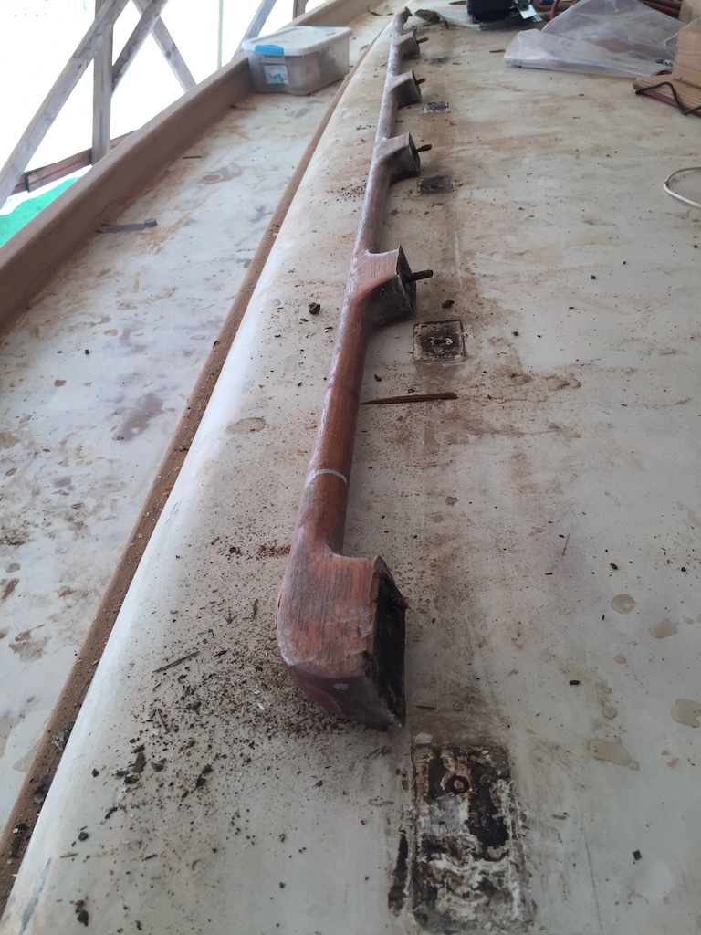
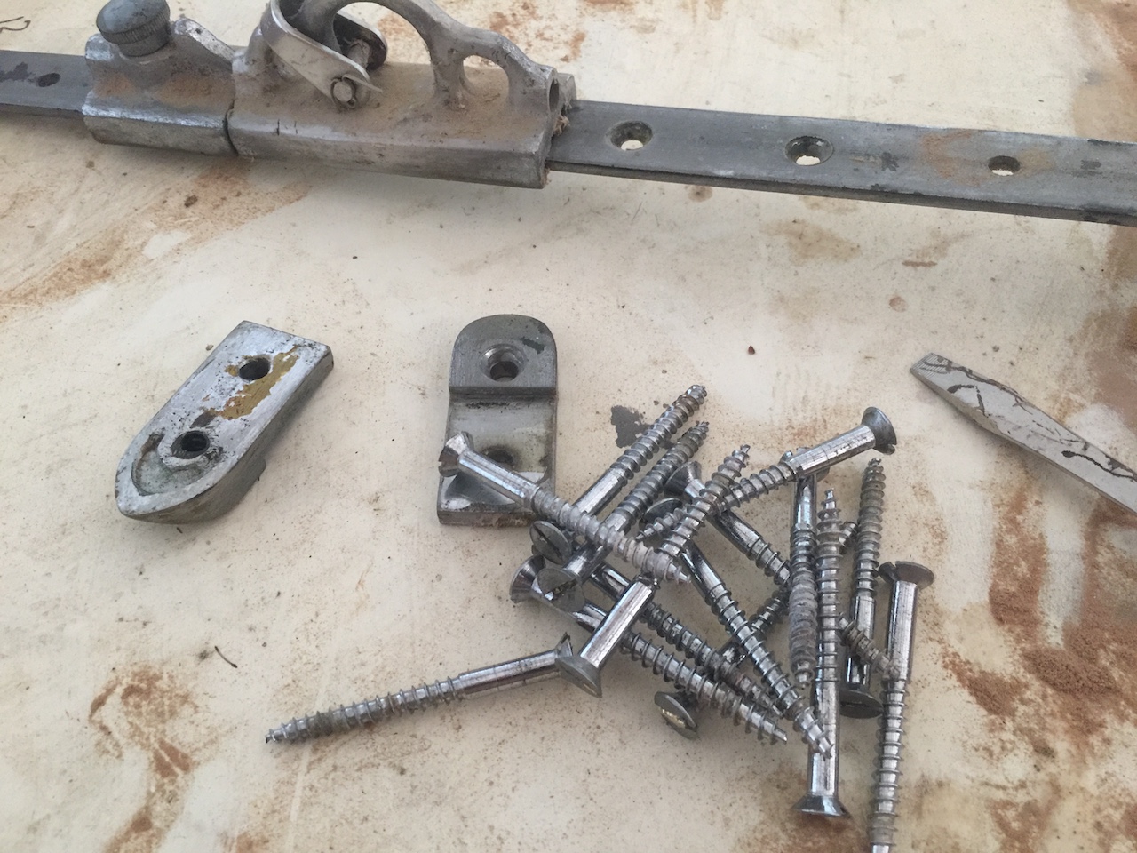
Some of the fastenings were quite corroded.
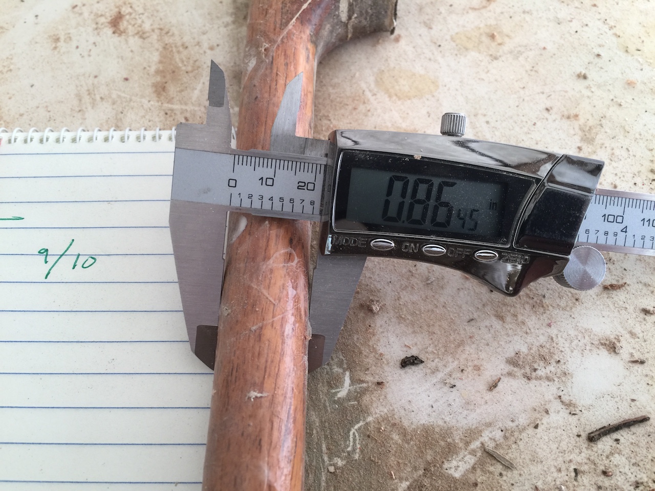
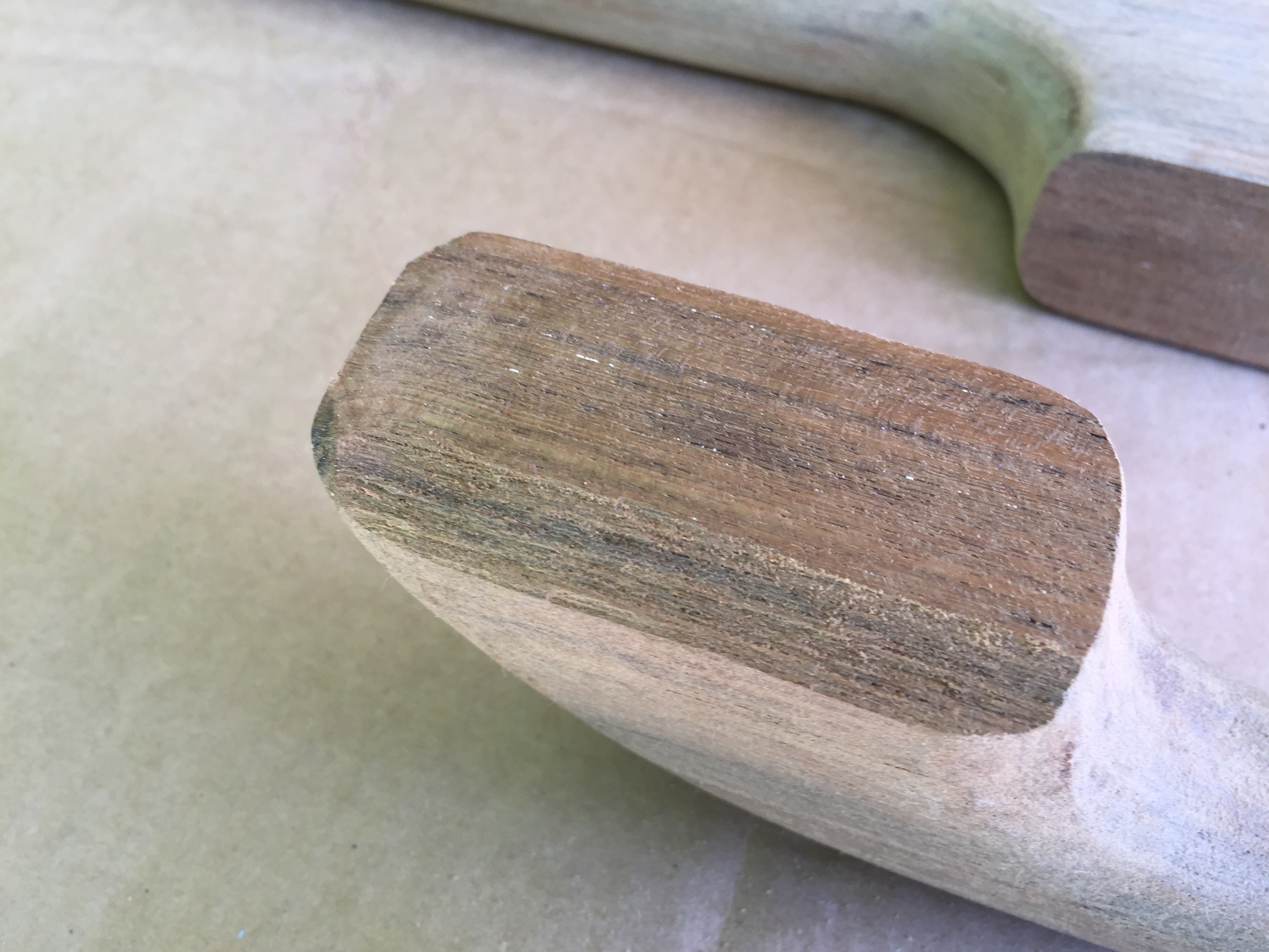
The handled are about 9/10 inches in diameter, which is almost certainly less than their original diameter.
The pads (for lack of a better term) are slightly asymmetric–square with the bottom on one side…
…and angled inward on the other. The angled side is the outboard side and the angling is an aesthetic choice that simply makes the rails appear more vertical than they actually are.
The hand-holds in the cabin were built into a molding that spanned the perimeter of the coachroof on the bottom edge (below the windows). This approach is fine, but a friend suggested that I might achieve in-cabin handholds by simply making matching a second set of matching handrails and through-bolt those on deck to those underneath. First, though, I needed to establish that the top of the roof and the underside were parallel. Otherwise, through bolting might not work.
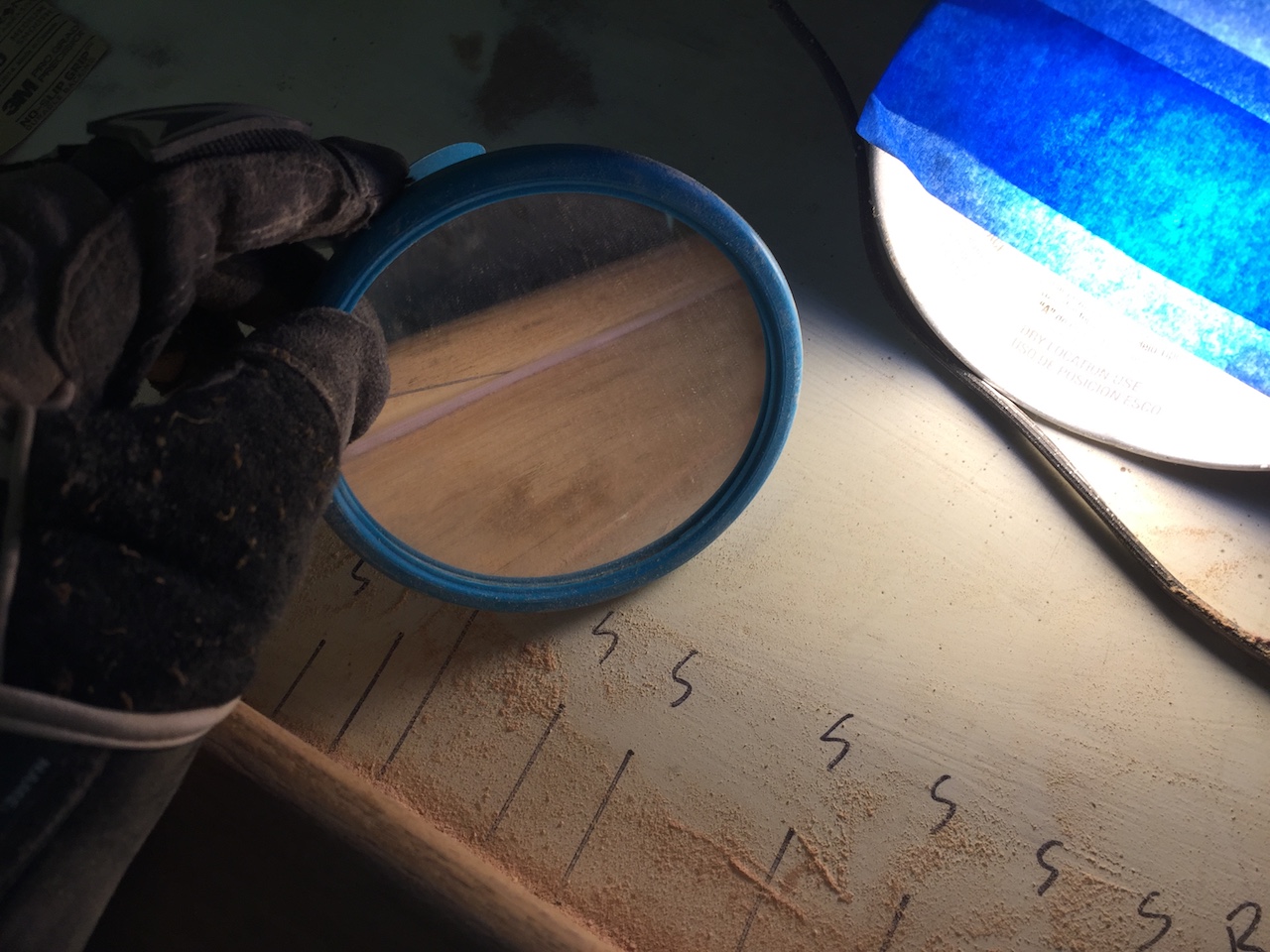
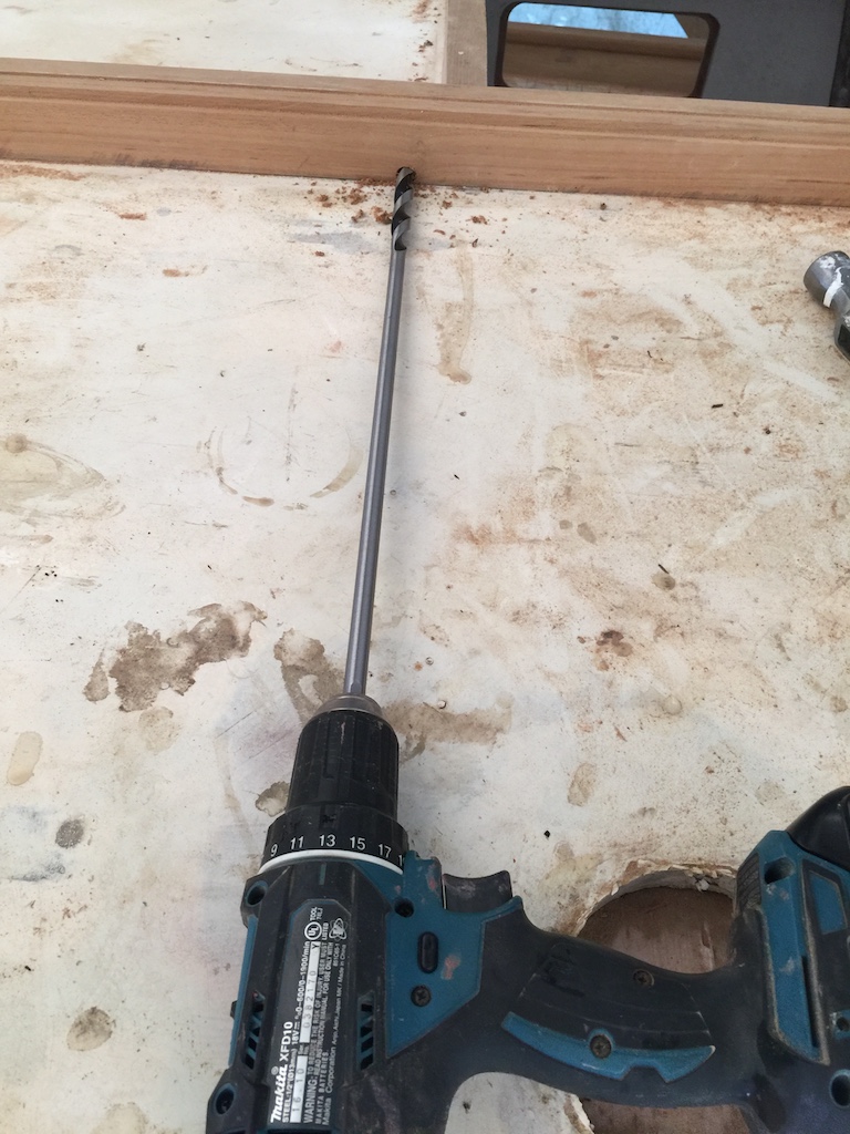
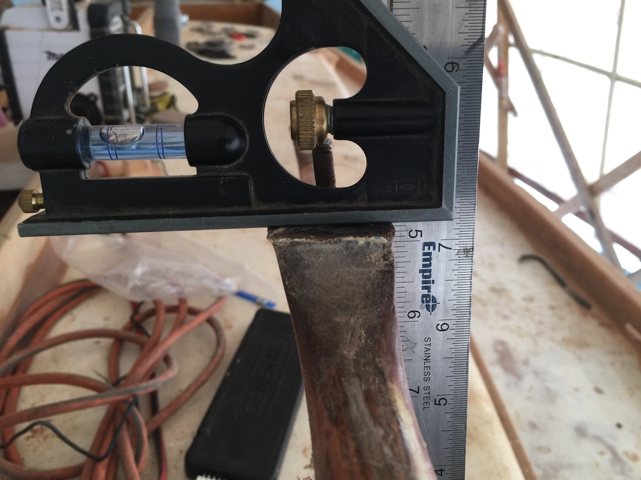
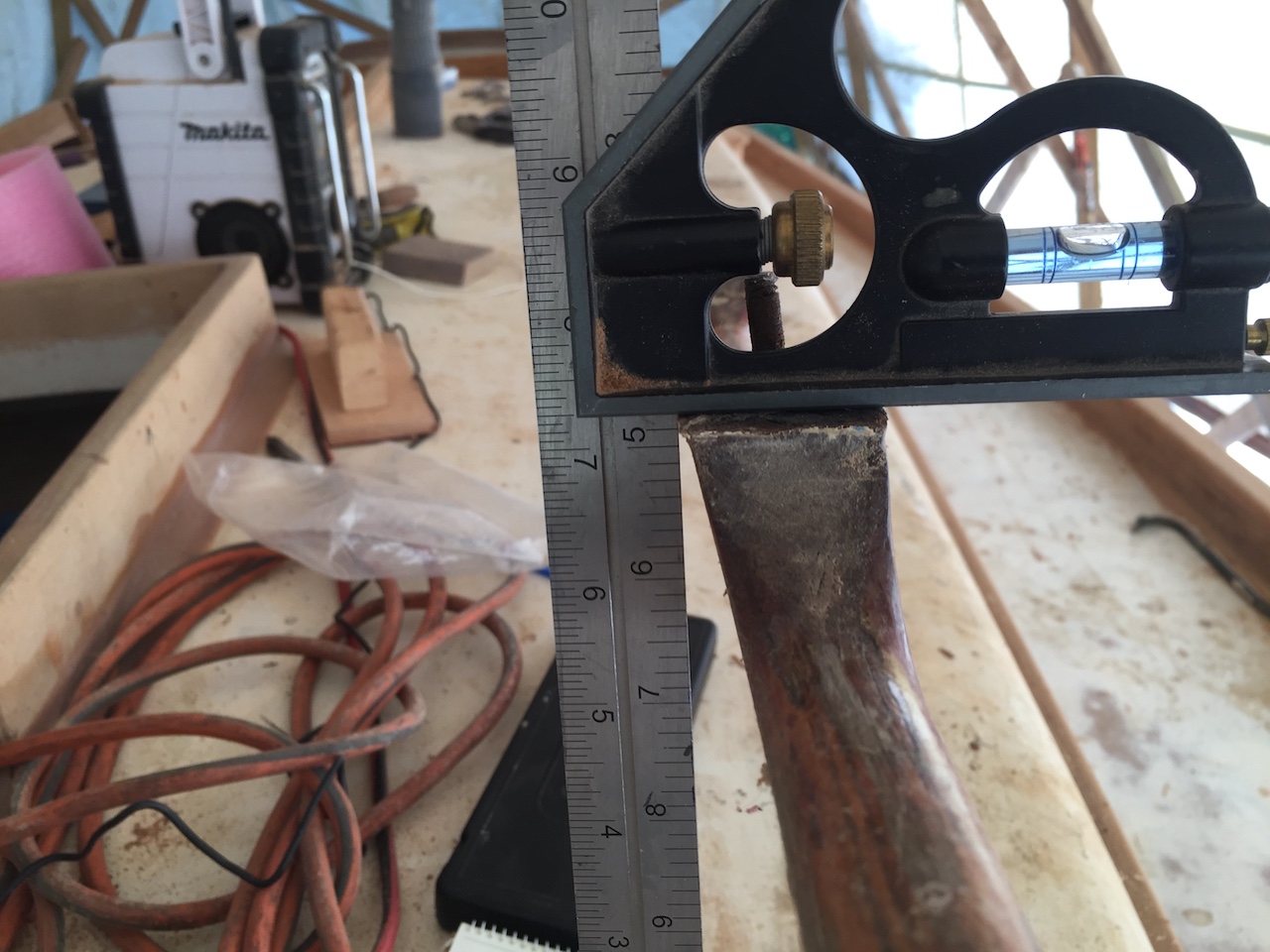
I began by using the drill press to drill a small hole through a piece of scrap teak. This hole is perpendicular to the surfaces of the wood, so I was able to use it as a jig to drill holes in the roof that are perpendicular to the top surface. (Obviously by this time I had planned out the location of the holes that will be used to bolt down the rails.)
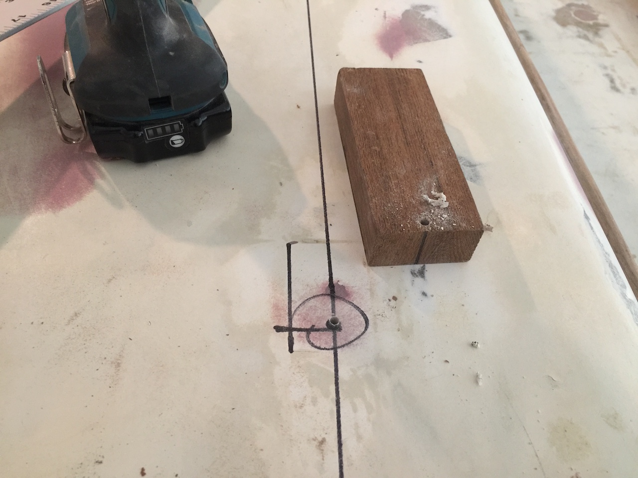
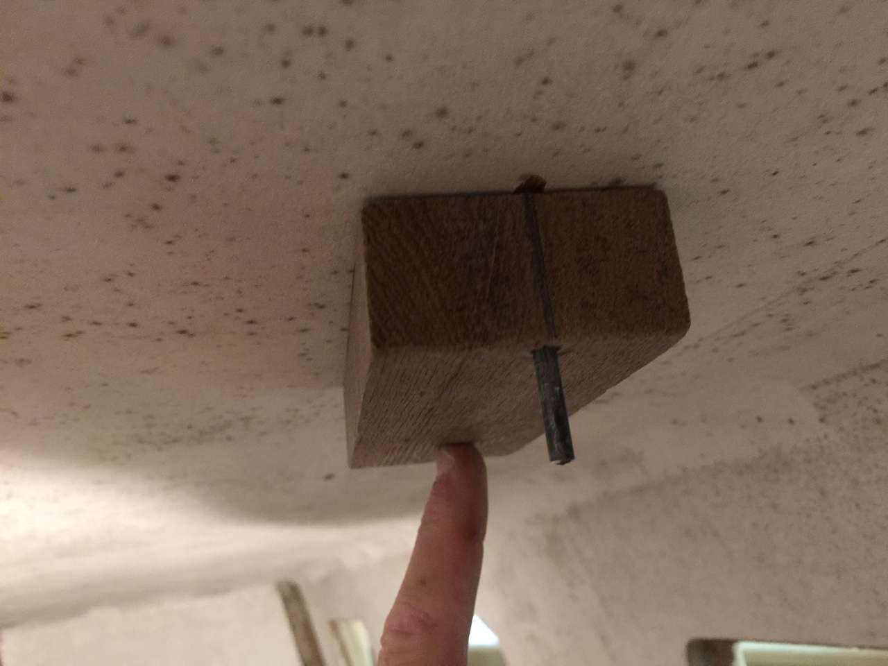
Going into the cabin, I drilled up through the roof with the same bit and jig. I know that the bit is, again, perpendicular to the top surface, so if the surface of the jig lays flat across bottom surface (the ceiling), then I know that the two surfaces are parallel. You can see confirmation in the photo below, and I was able to make a similar confirmation with the other 23 holes.
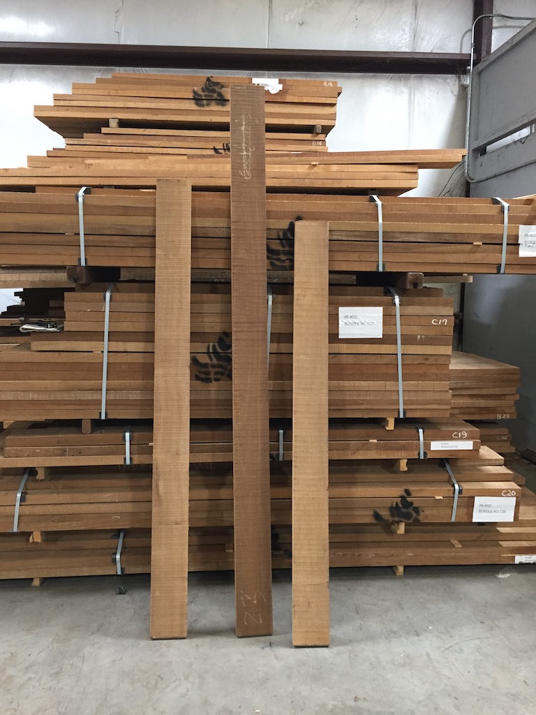
Having settled on the “matching pairs” approach, I was able to purchase whatever teak I need for the job.
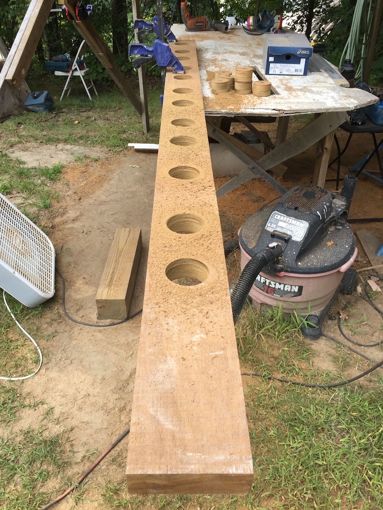
The process I will describe here is the standard way to make handrails. They almost always come in port-starboard pairs, so this two-at-a-time process makes a lot of sense. It all starts with a lot of careful measurements. Next, I used a drill with a 3-inch hole-saw bit to cut out the pre-planned holes.
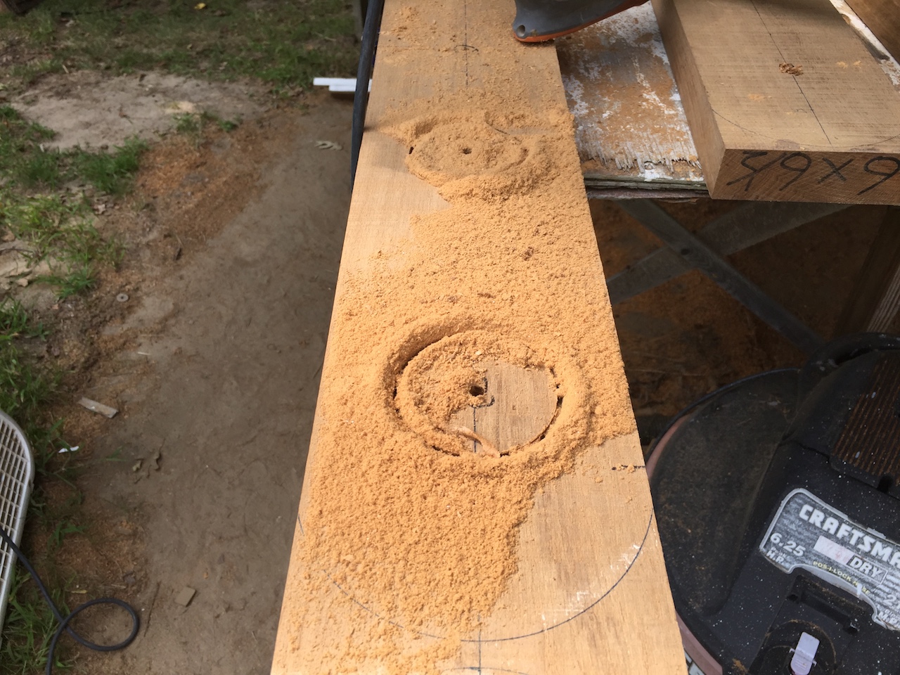
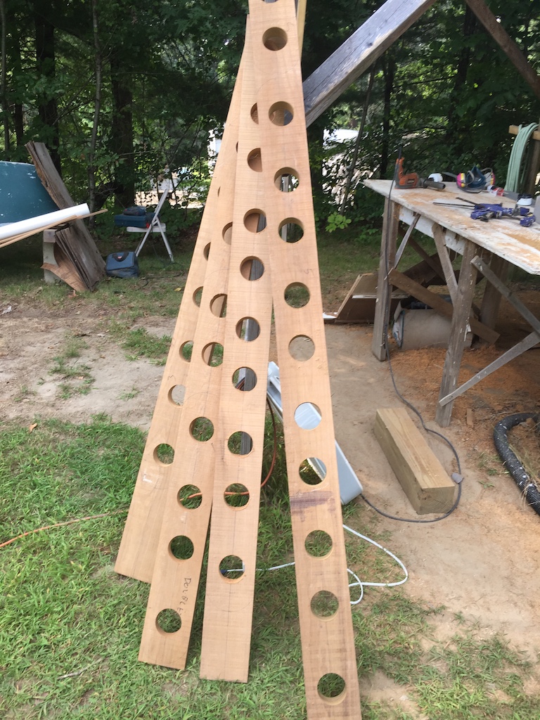
Lines are traced between some of the holes, and I used the jig saw to roughly cut out the middle parts. Next, I used the router and a straight-edge as a guide, and cleaned up the perimeters of the holes.
The amount of unavoidable waste in carpentry work is often significant.
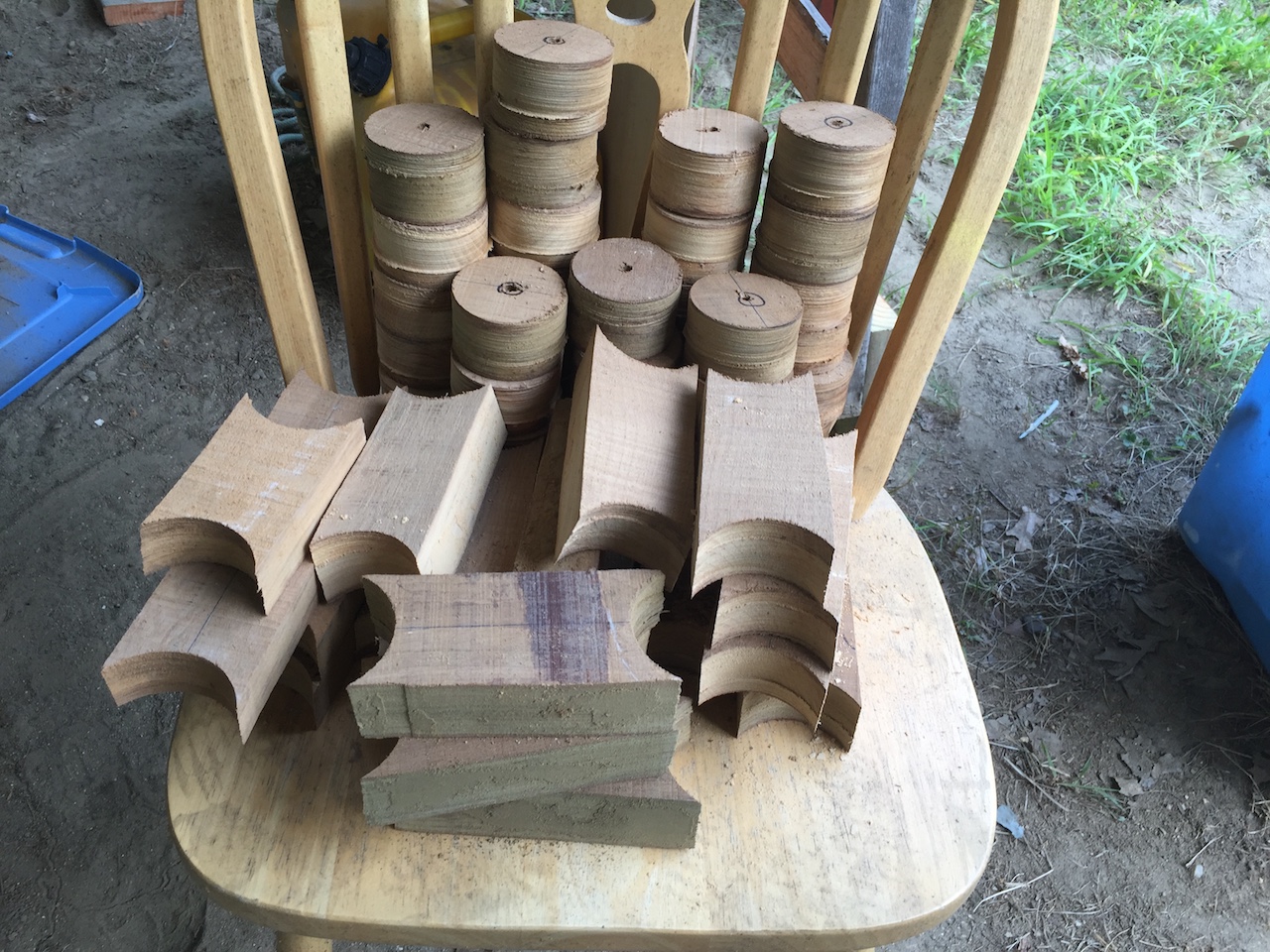
Next, I ran the boards through the table saw to cut them exactly in half lengthwise, and now I have my rough rails.
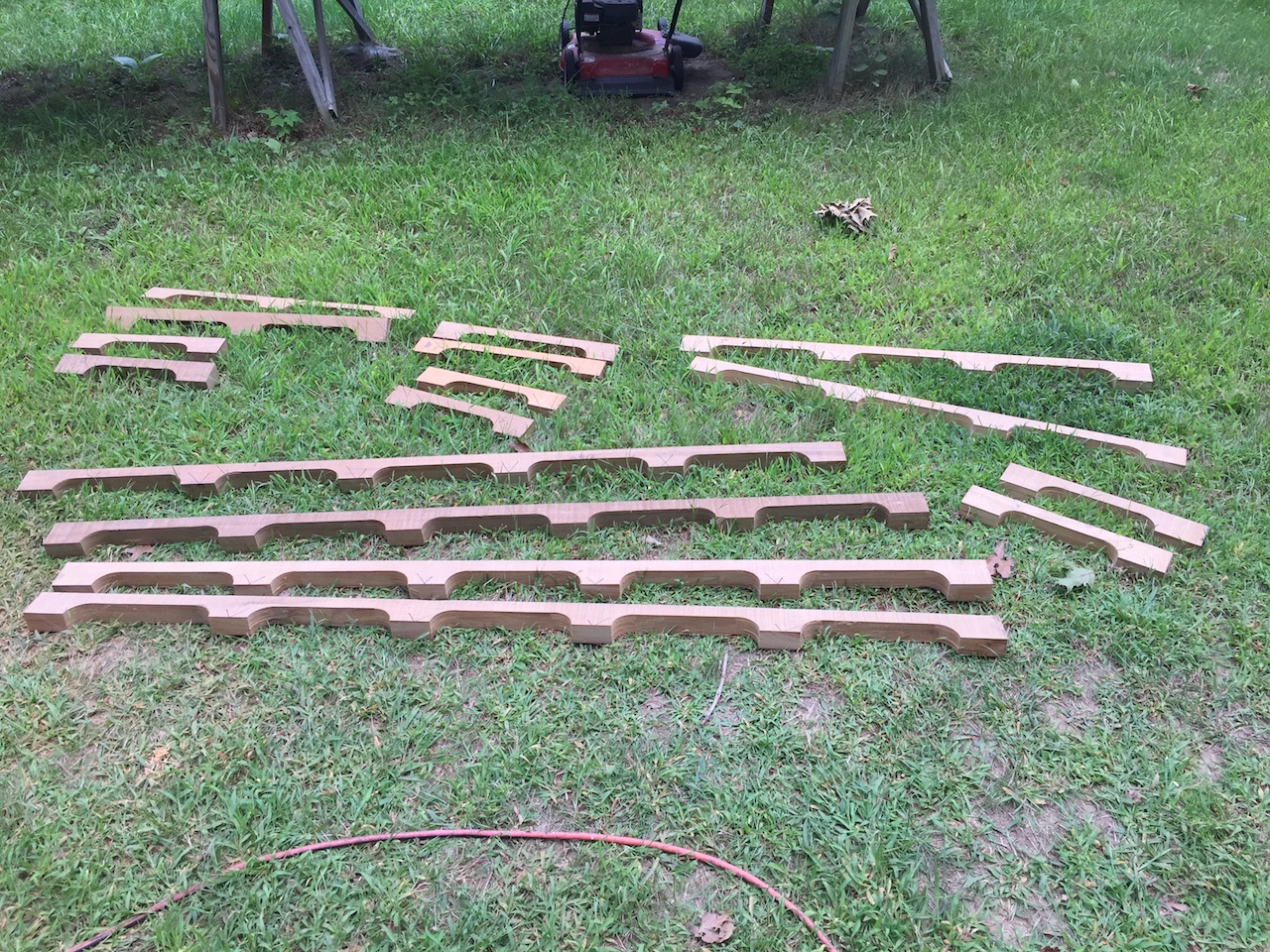
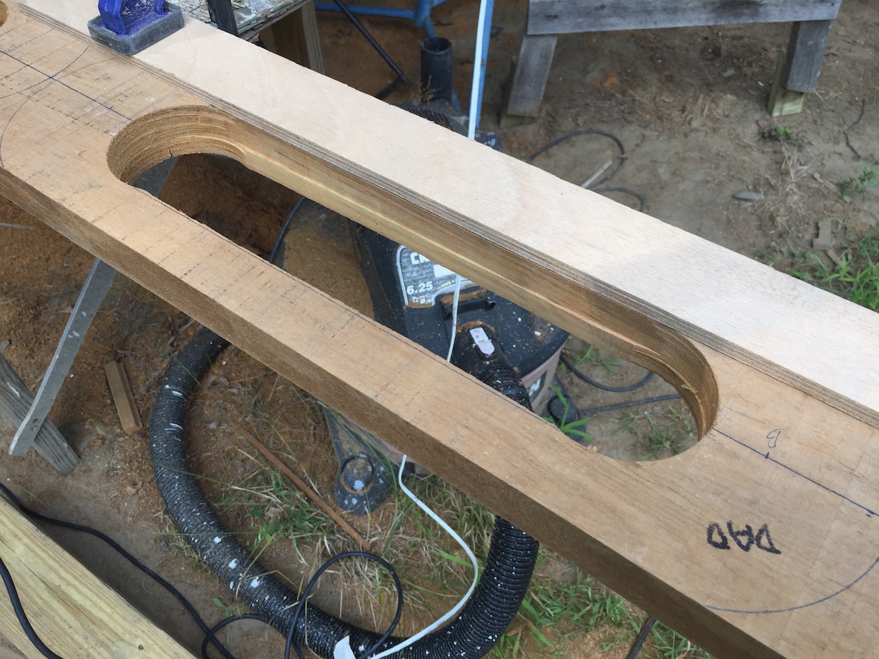
Using an old cereal bowl and a pen, I traced the round-overs on the ends and used the jig saw to roughly cut them, and then the table sander to clean them up.
Next, using the table saw, I cut the “angling in” bevel at about the same angle as in the original pieces.
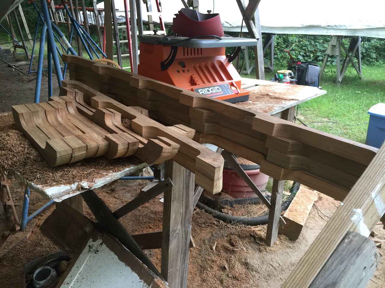
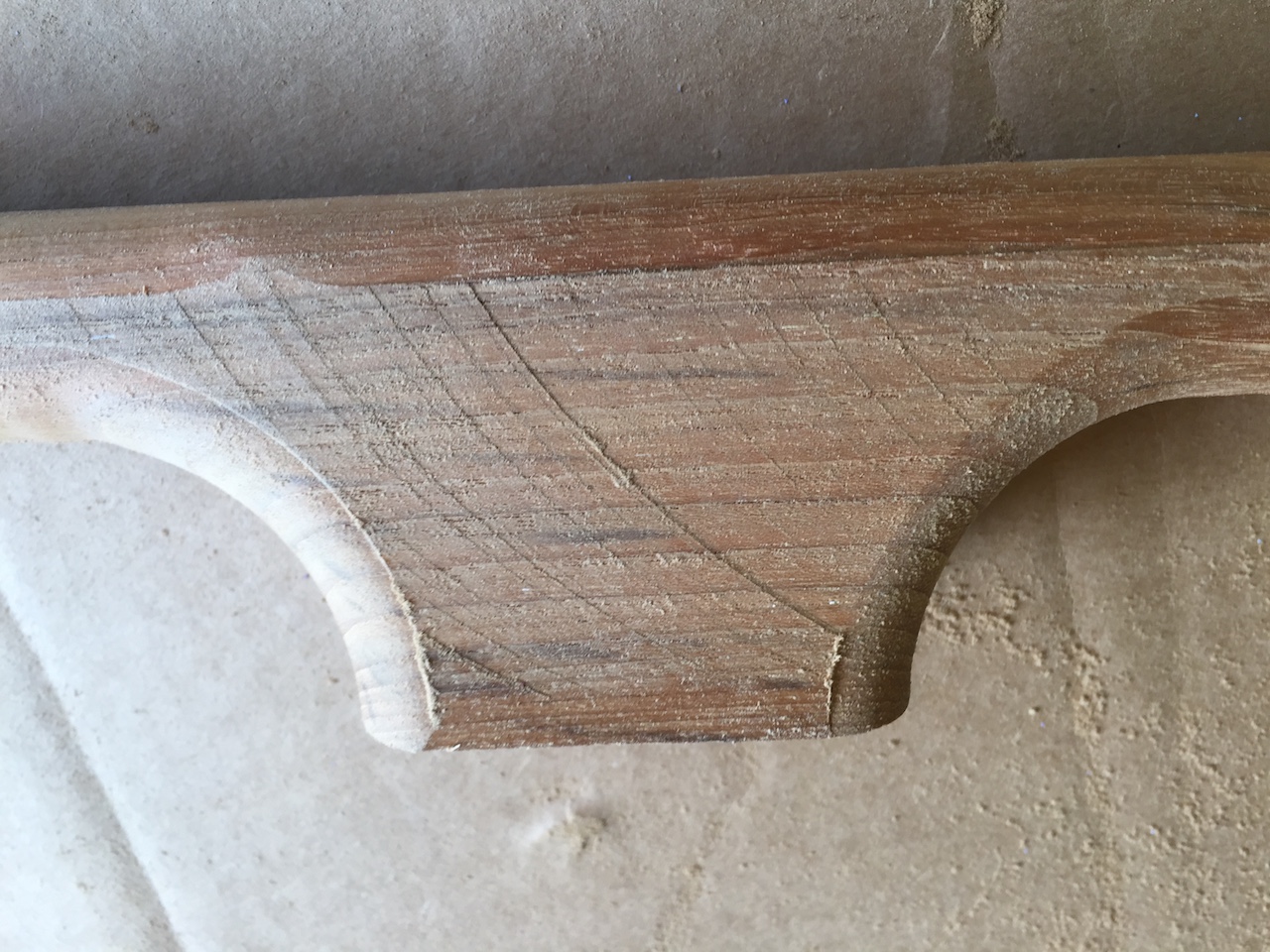
Using the router again, this time with a 1/2-inch round-over bit, I rounded off the rails everywhere but the perimeter of the bottoms of the pads.
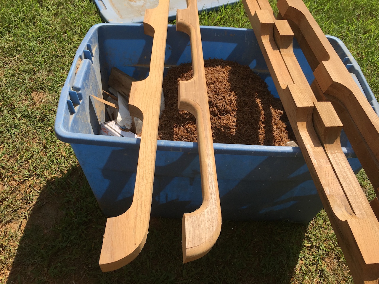
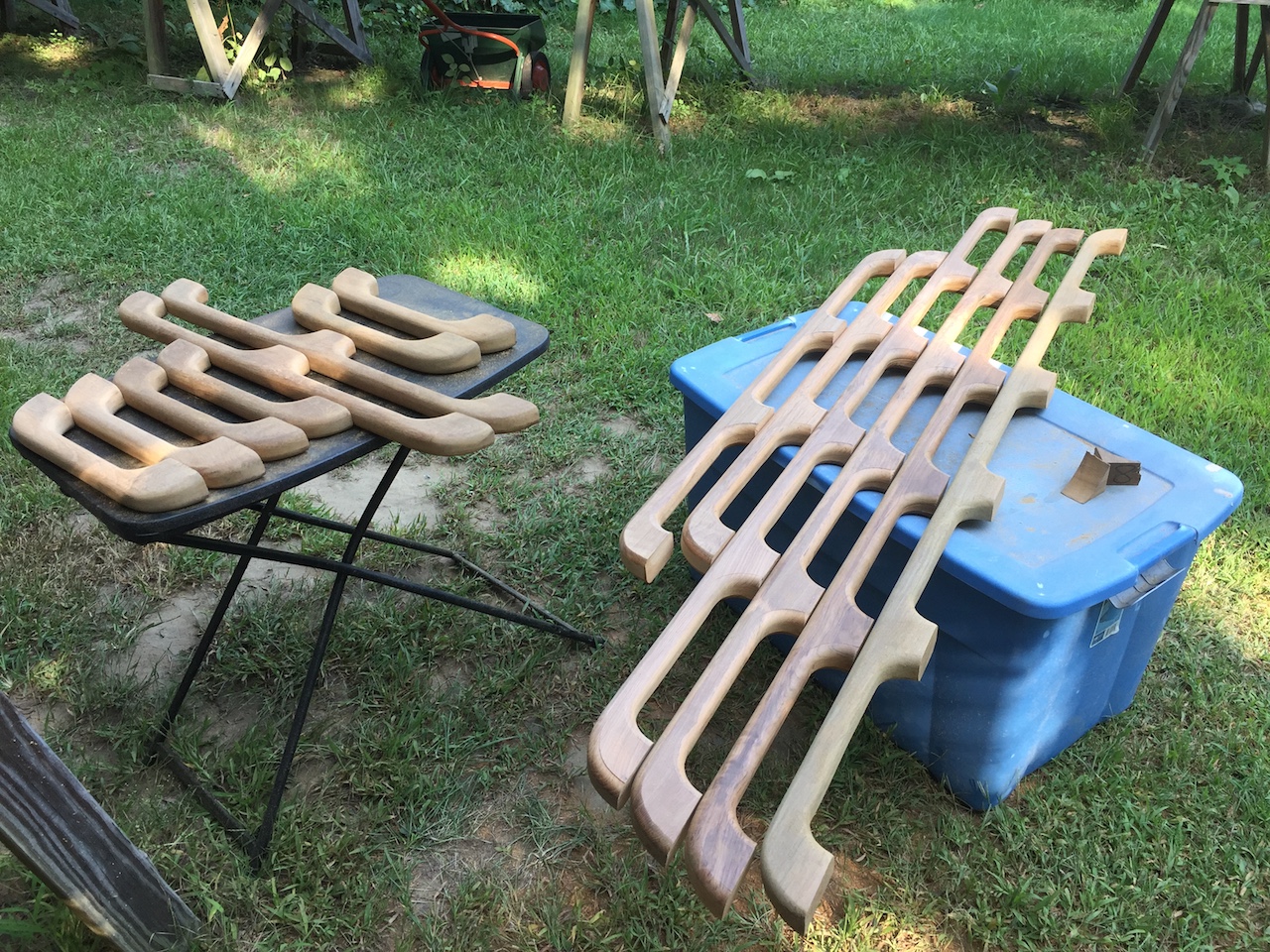
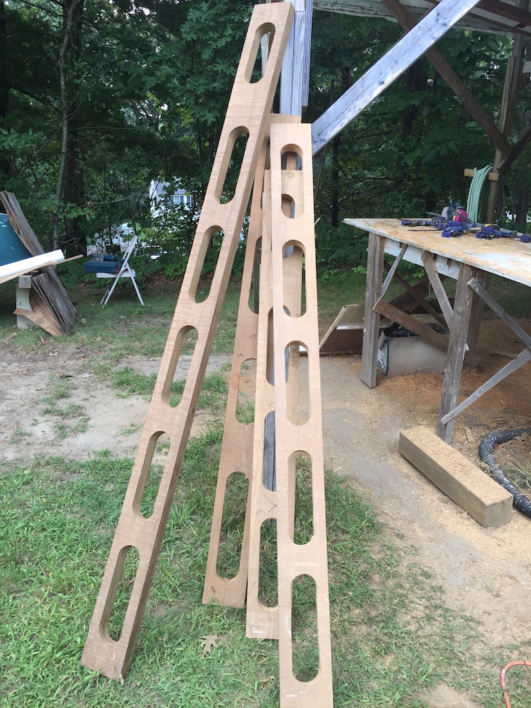
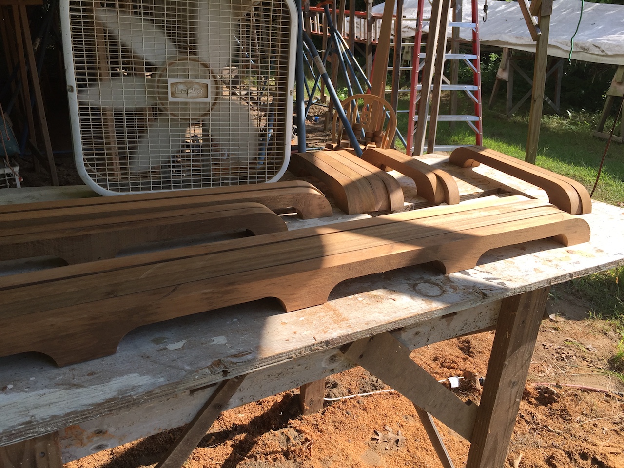
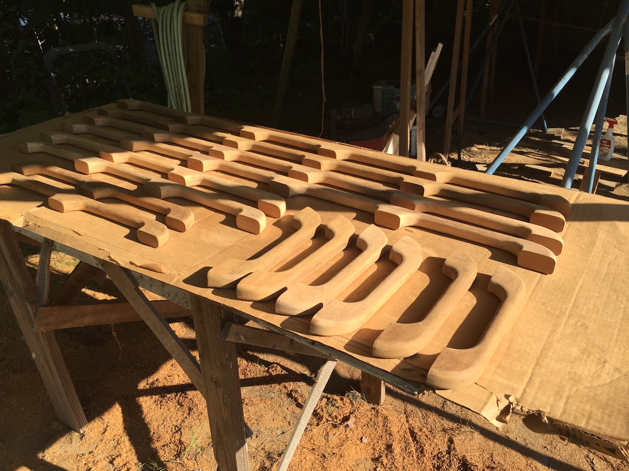
They look pretty much complete here, but there’s still a lot of sanding to do to remove machine marks and mistakes made while using the various saws, drills, and routers.
Finally, everything is sanded, but there will be more sanding later.
This gives you an idea of how the matching pars will be aligned. You can see clearly here why it is important that the top and bottom surfaces of the roof are parallel. One bolt will secure both pads.
I took everything up to the boat for a dry fit. The rails will follow the curve of the but here they are obviously straight.
After some deliberation, I decided that there’s a little too much clearance under the rails–well more than necessary for wrapping a gloved hand around, but also making the rails a little taller than I like. For one, the taller they are, the less comfortable they are to sit on when sitting on deck. For two. the lower the profile, the stronger. For three, cutting about 1/4 inch off the bottom of each pad will remove some imperfections left over from machining and sanding.
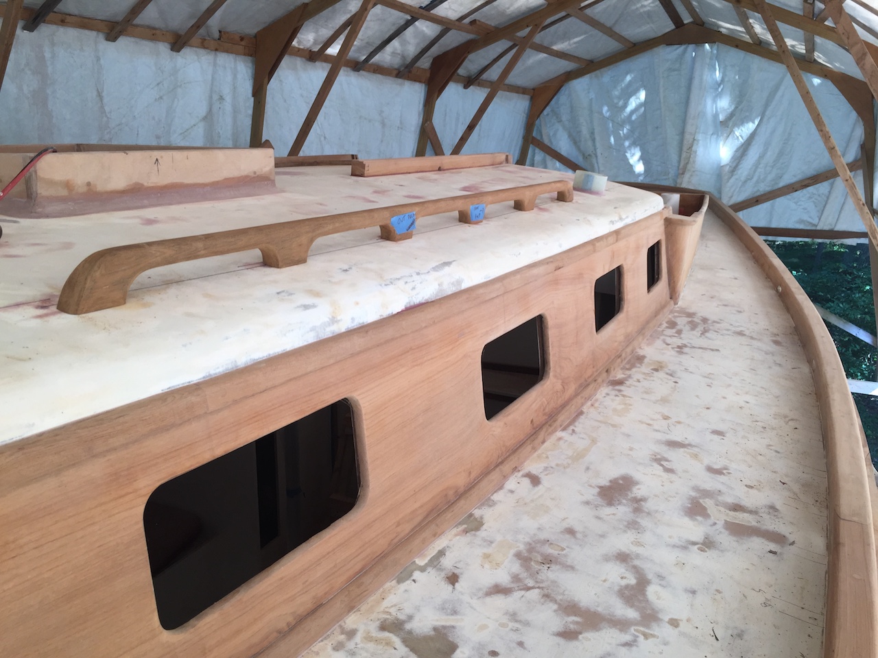
So, I used the table saw to carefully take about 1/4 inch off the bottoms of the pads. and the difference is perceptible in the following photo. (Note the fiberglass tube installed in the port-aft vent hole.)
These new rails will be much stronger than the old ones.
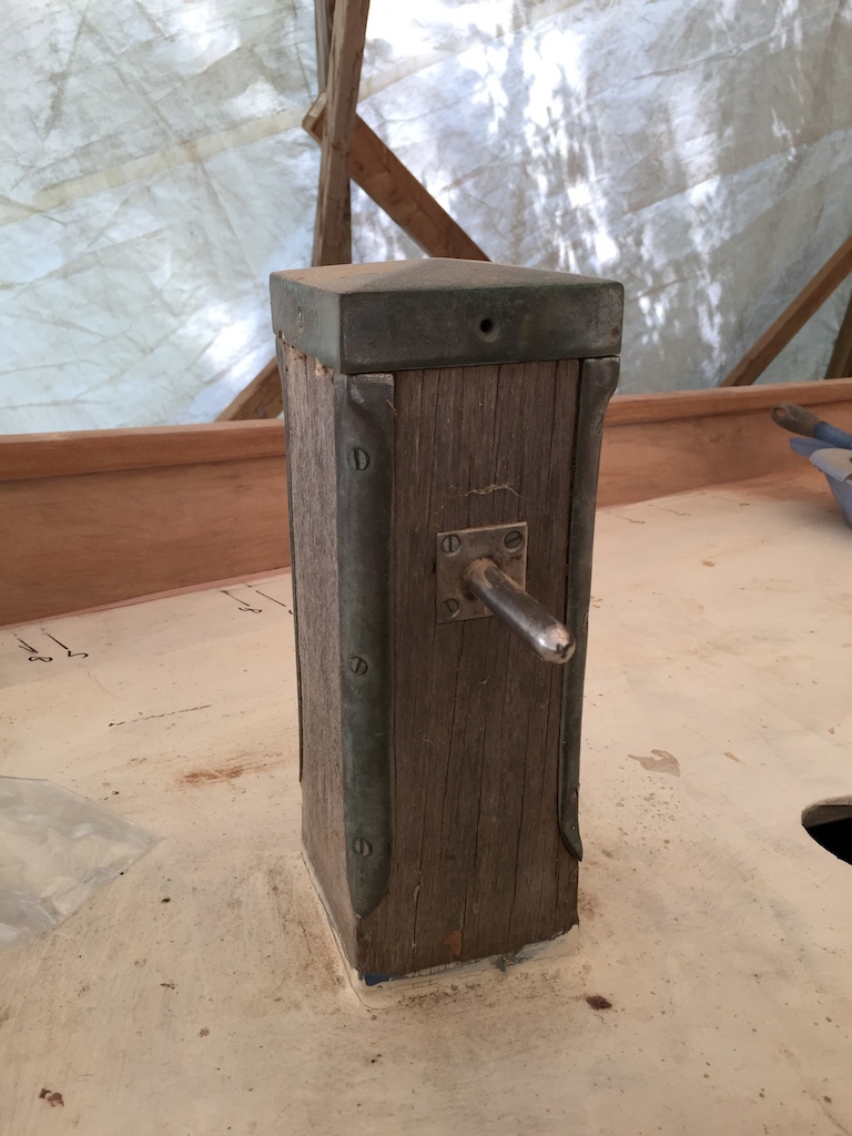
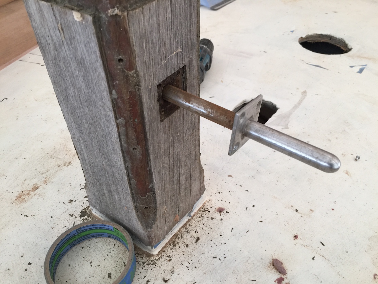
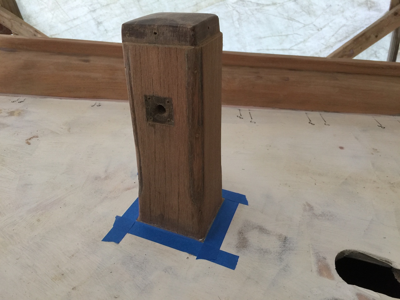
Meanwhile, there are other odds and ends to take care of. I removed the hardware from the Samson post, and sanded it down.
I finally finished the epoxy filleting around the cap rails.