2/9/19: Cockpit Gratings I
From an article in PRACTICAL SAILOR:
A snug-fitting teak grating adds safety and a touch of class to the cockpit of any boat. Spray or rain runs under the grating to the cockpit drains, leaving a reasonably dry footing for hopping about the cockpit as you haul in sheets to tack or trim sails.
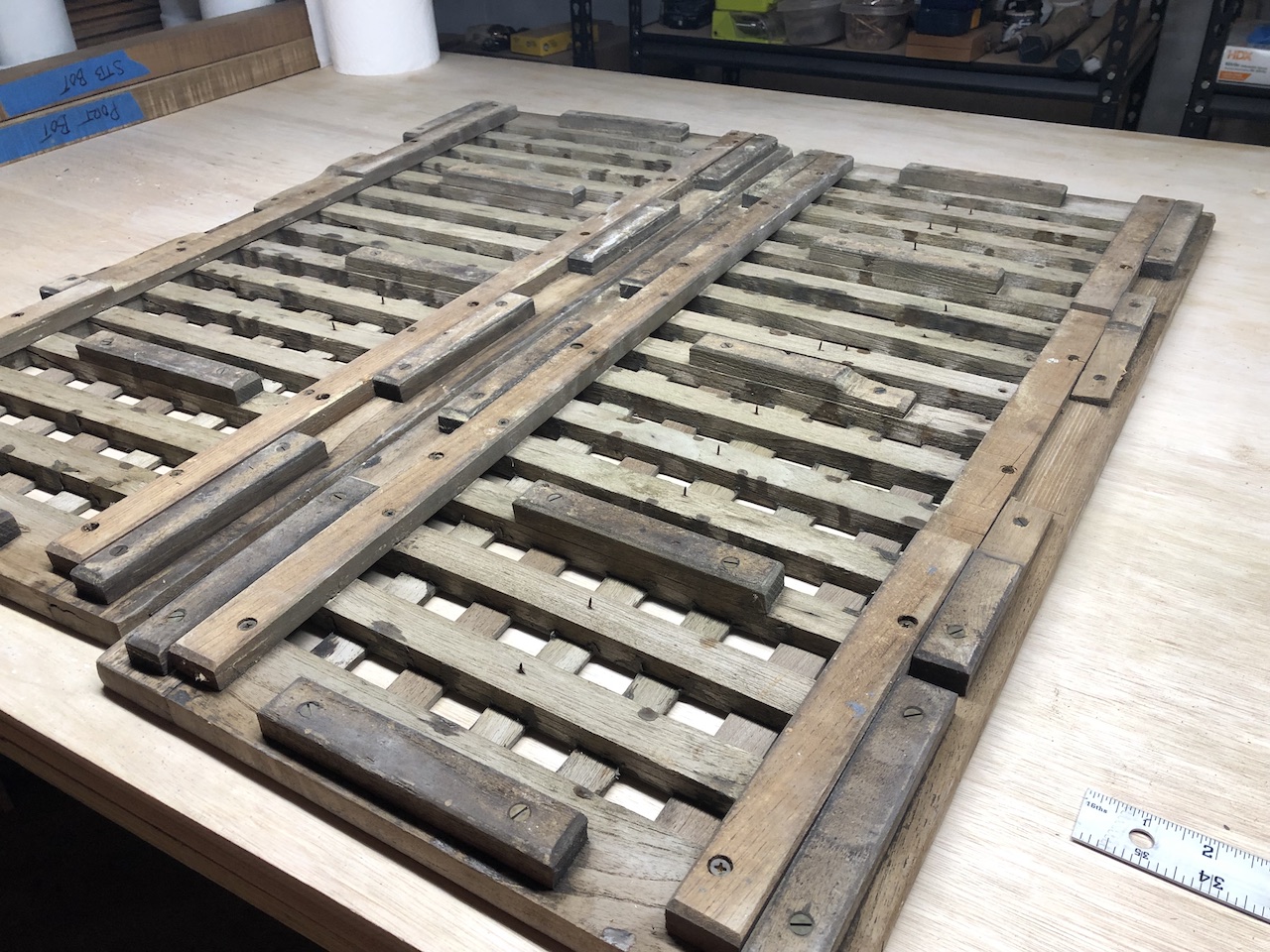
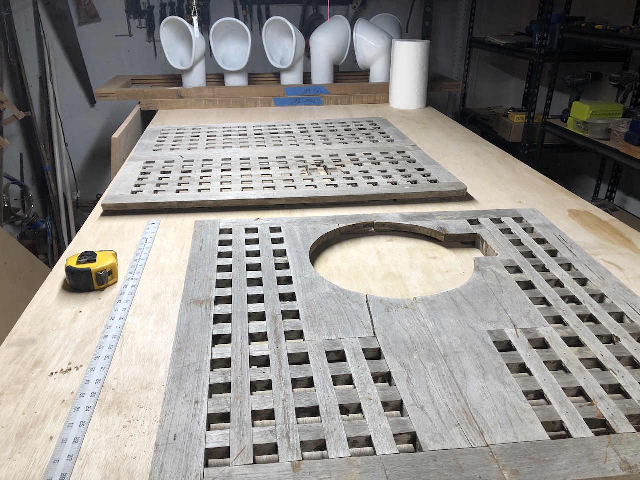
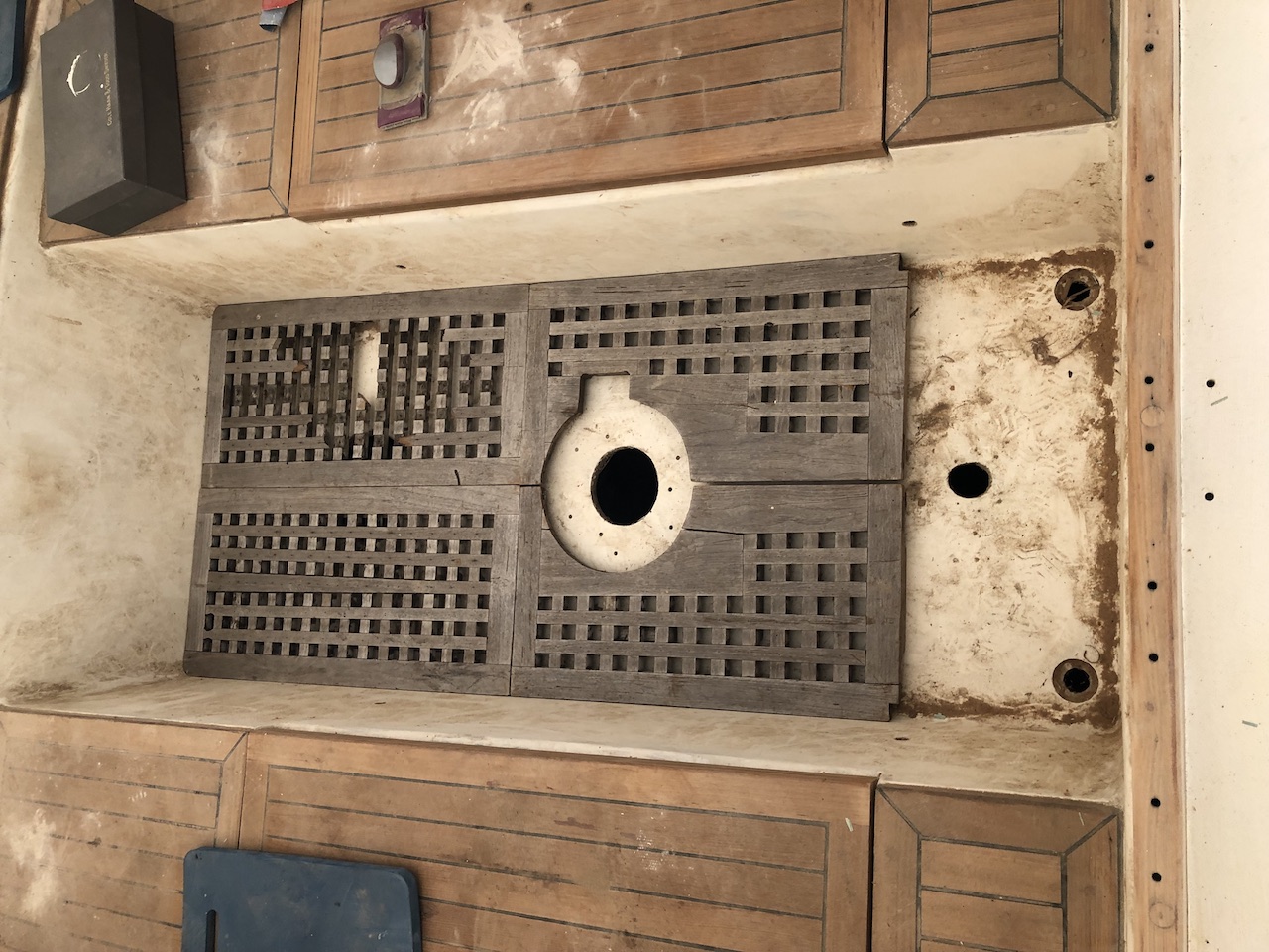
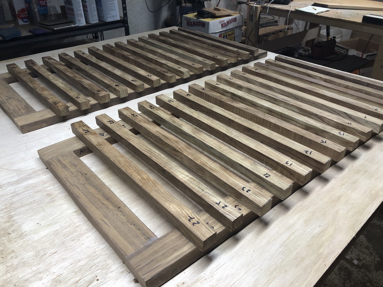
Thalassa’s original cockpit grating consists of four pieces that are now worn and damaged.
The round opening is for the steering pedestal base.
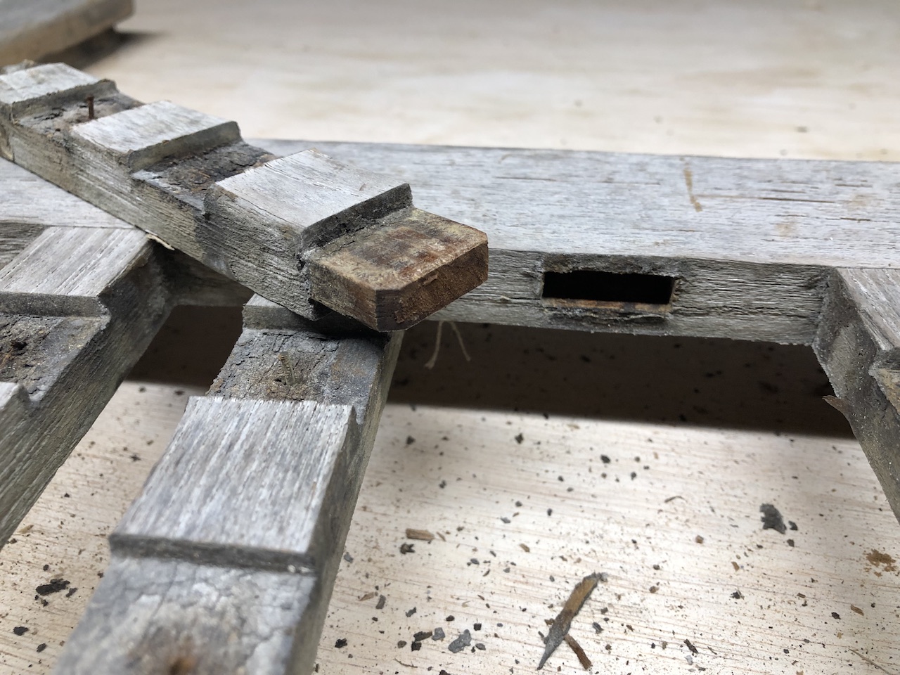
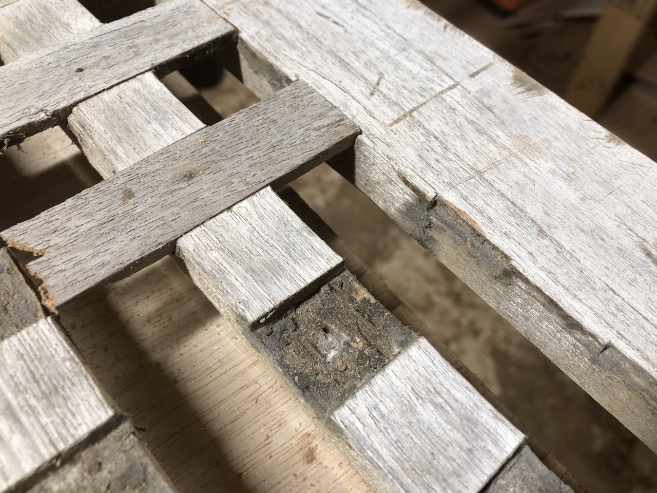
My plan is to use the old gratings as templates, but my construction methods will differ somewhat. As you can see below, the transverse members are attached to the frame by mortise and tenon joints. Obviously, then, the frames were assembled at the same time that they were fitted with the transverse members (obviously you cannot not fit the tenons into the mortises in a completed frame). I have neither a mortising machine, nor the patience and skill to cut about 100 by hand, not to mention the time to plan out the process.
Here are the original gratings on the cockpit sole. At the aft end of the cockpit was a built-in box/lid that served as a little storage bin, and concealed the few inches of rudder-post that protrudes above the cockpit sole.
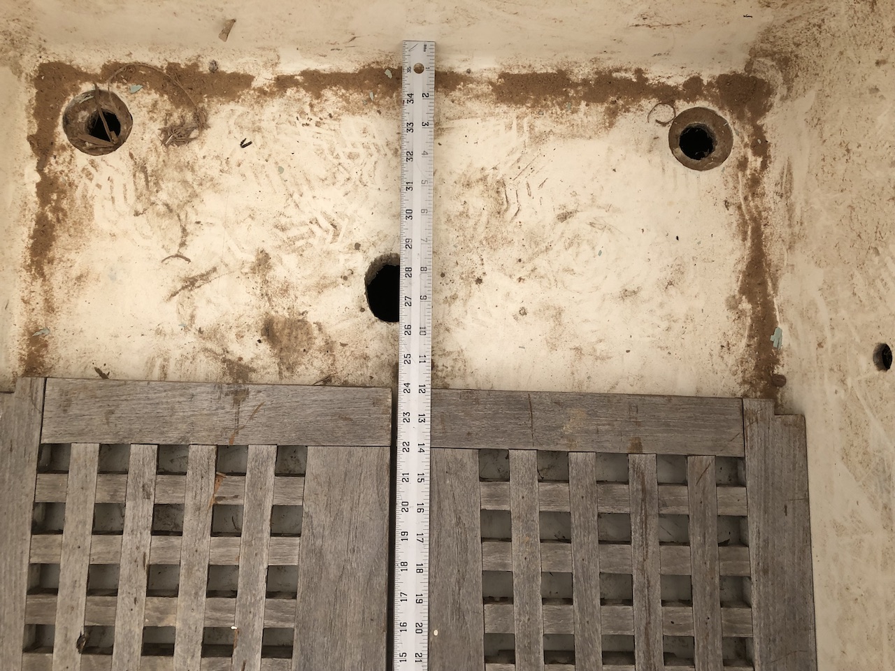
I’ve decided to steal this area, and give it back to the cockpit sole. The result will be a little more room to move behind the wheel, and a few more places to sit in an already very roomy cockpit. The aft two gratings, however, will have to be about 12 inches longer than the originals.
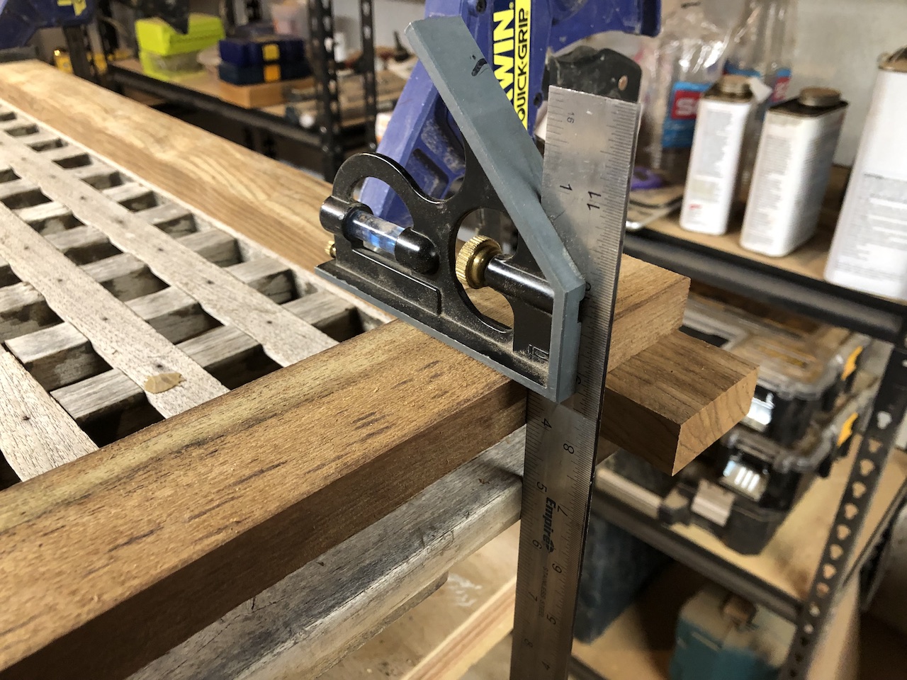
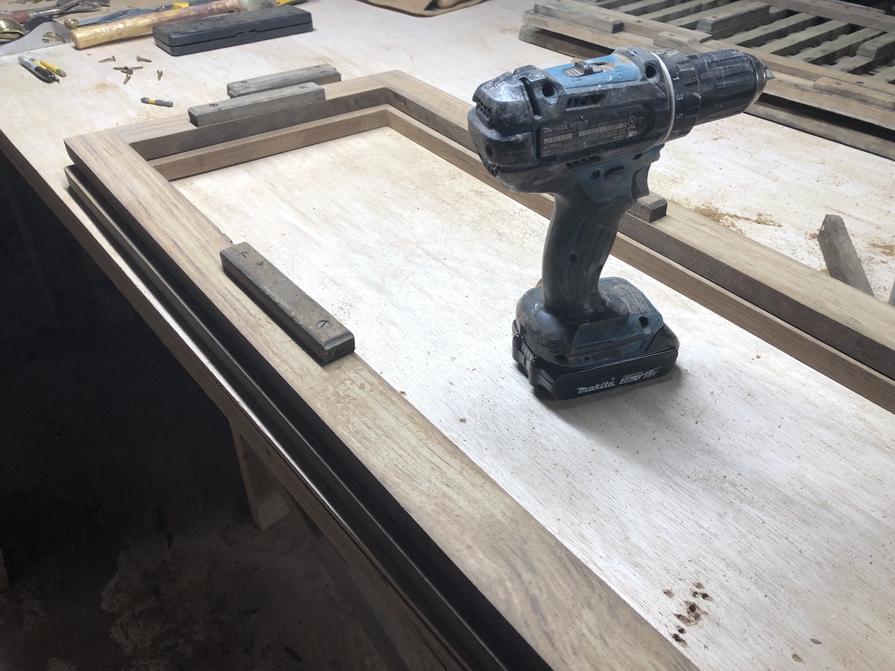
Frames first, starting with the forward two. One of the challenges here is that the gratings are not square, as the cockpit sole is wider forward than aft. Thus, the half-lap joints will not be square.
After carefully marking the inside end of the joints, I used the circular saw (with depth set to about 3/8 inch) and a guide to cit on the line, and more cuts to remove additional waste.
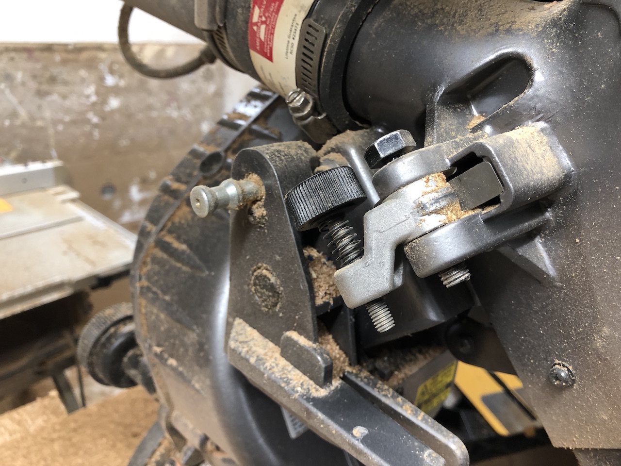
I also employed the miter saw extensively, using the “depth stop” to control the depth of the cuts.
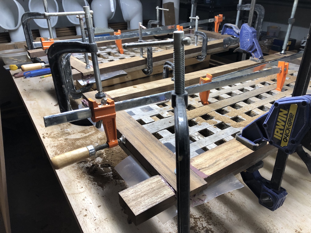
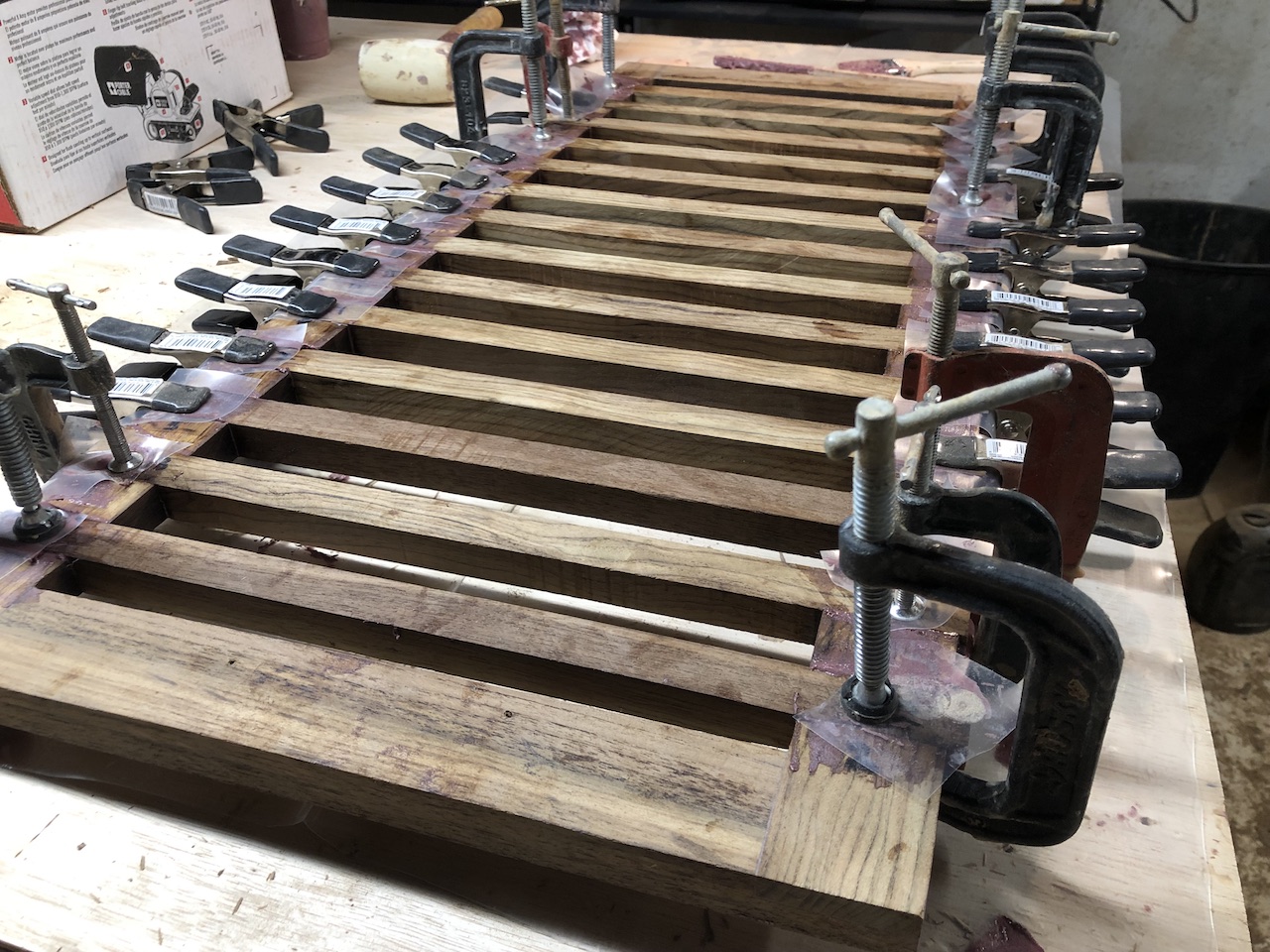
Here the eight joints are glued and clamped.
The gratings don’t sit directly on the sole, but are supported by strips of teak that are screwed into the bottom side. I added some temporary supports for the purpose of test fitting in the cockpit.
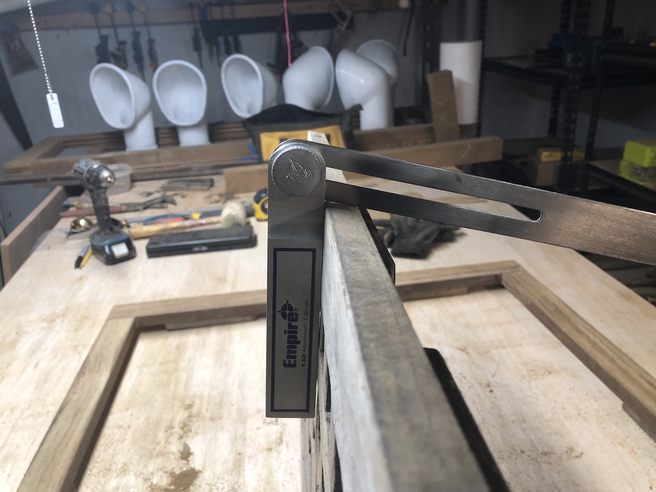
The cockpit sides are angles slightly outward, so the forward and outer sides of these frames received a slight angle.
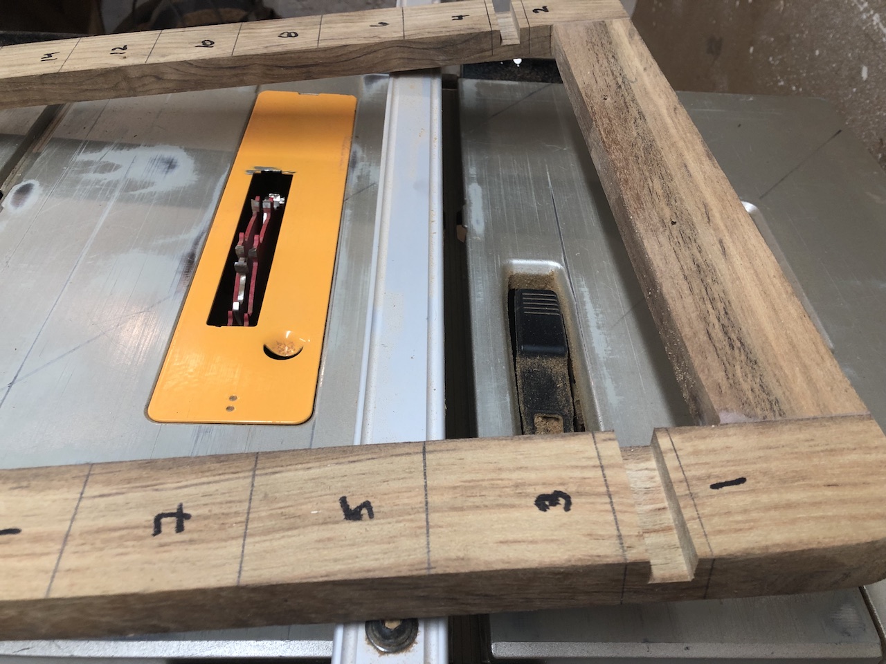
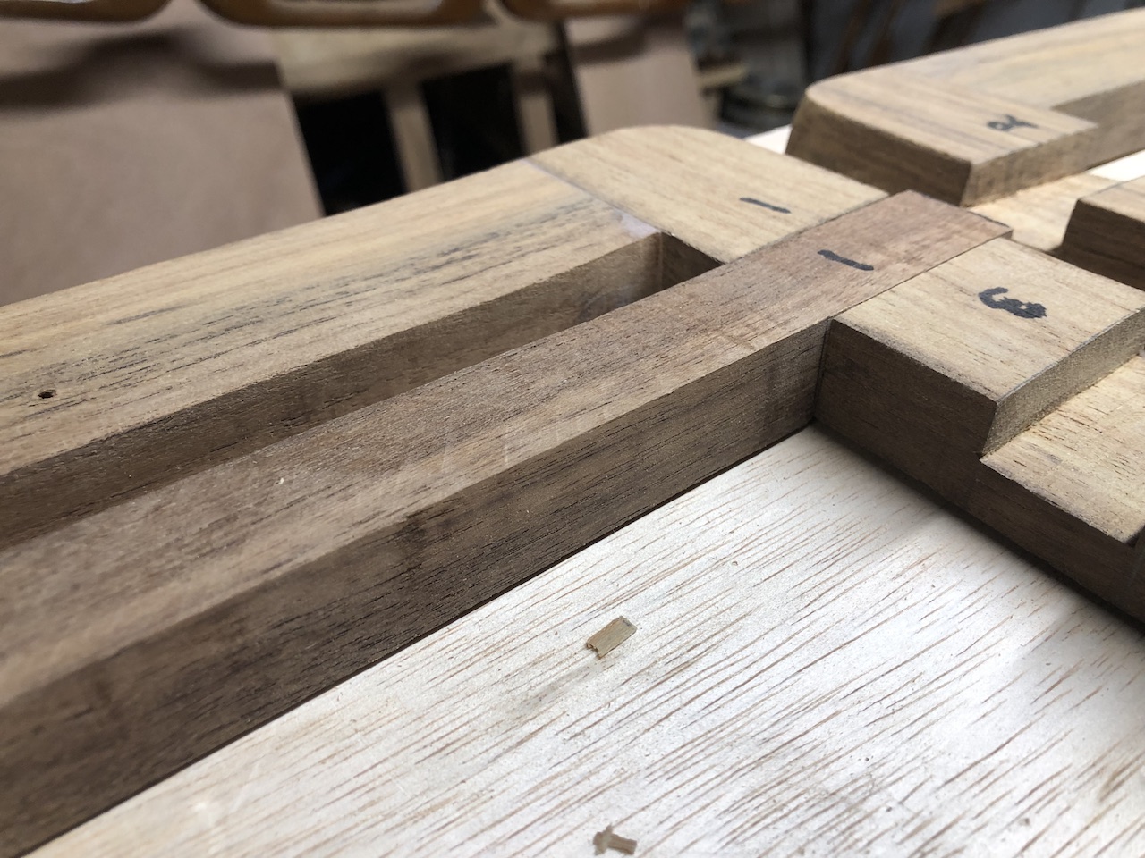
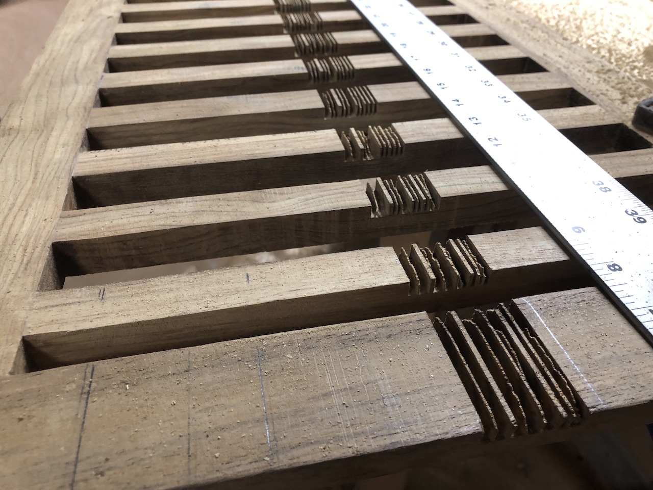
The transverse members are about 1 inch wide, but not identical…
…so each joint had to be marked by the piece that would eventually make the joint.
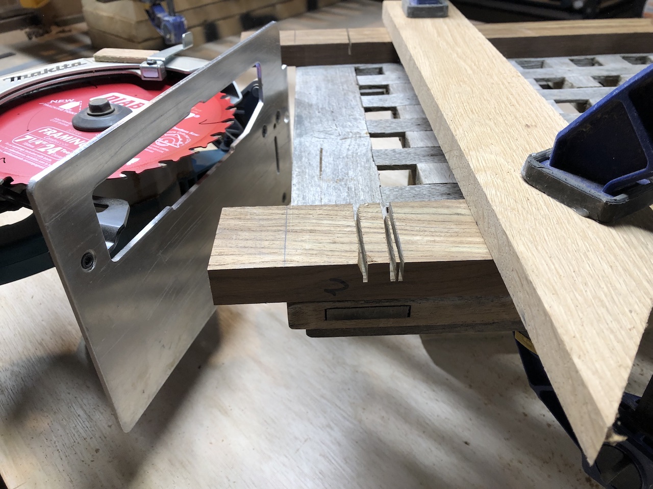
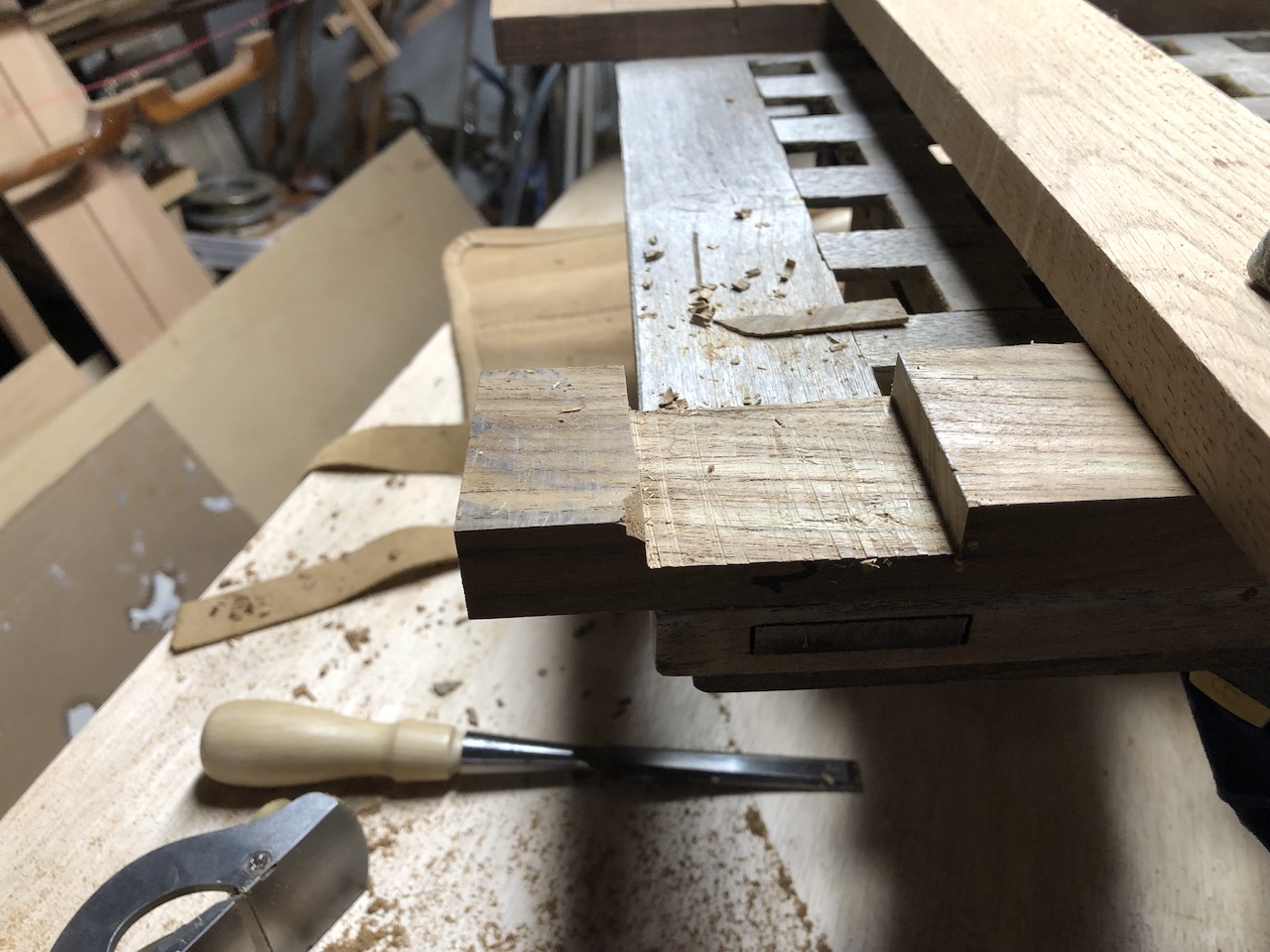
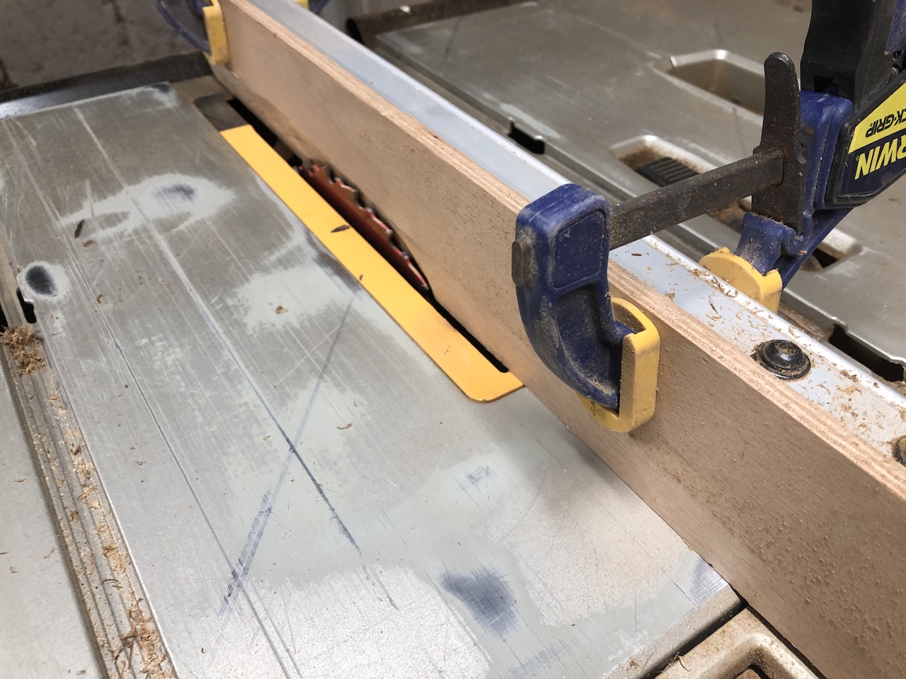
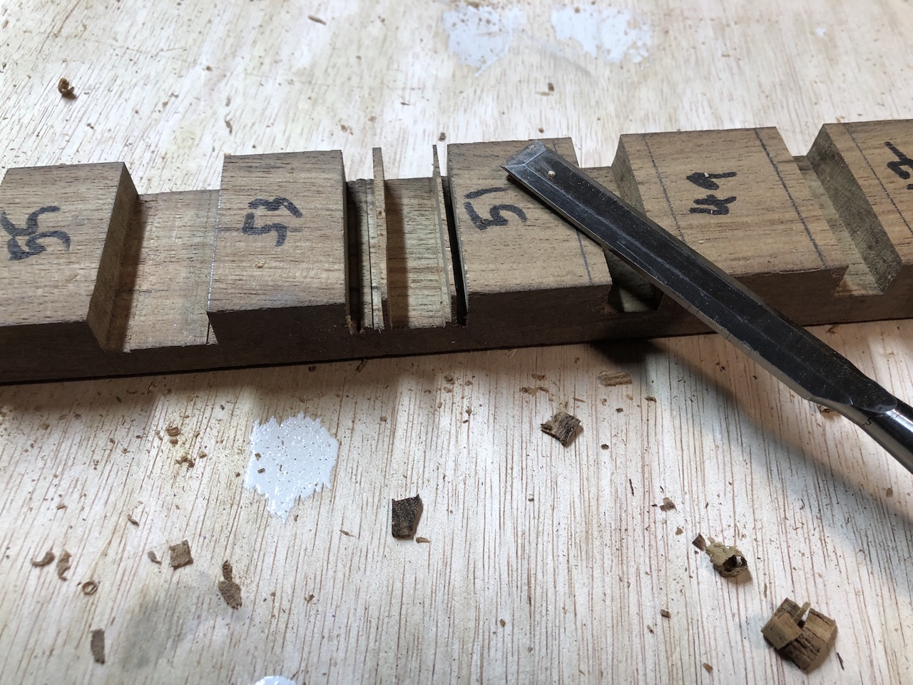
There’s a lot of material to remove in these 56 joints, so I roughed out the middle by hand using the dado set in the table saw.
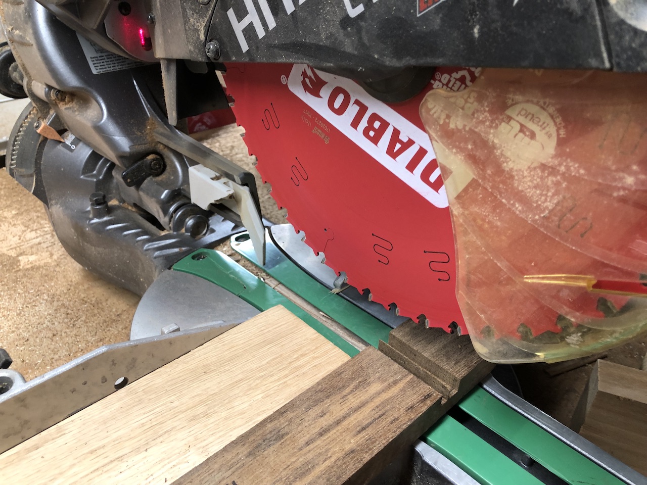
The rest of the material was removed with the miter saw, and sharp chisels took care of the leftover.
The transverse members were cut in a similar way…
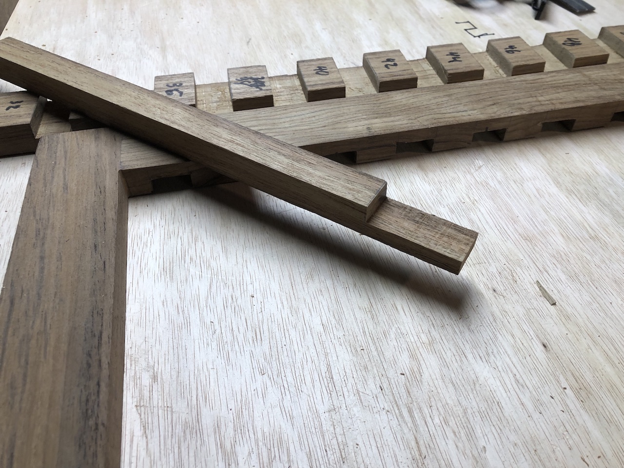
…but the depth is slightly different.
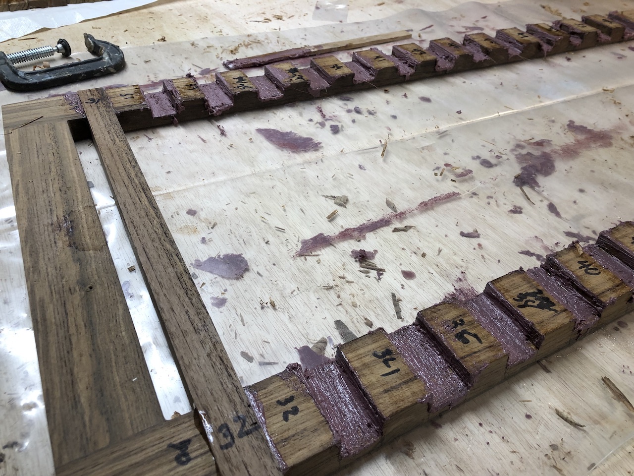
Here the glue (thickened epoxy) is in place and ready.
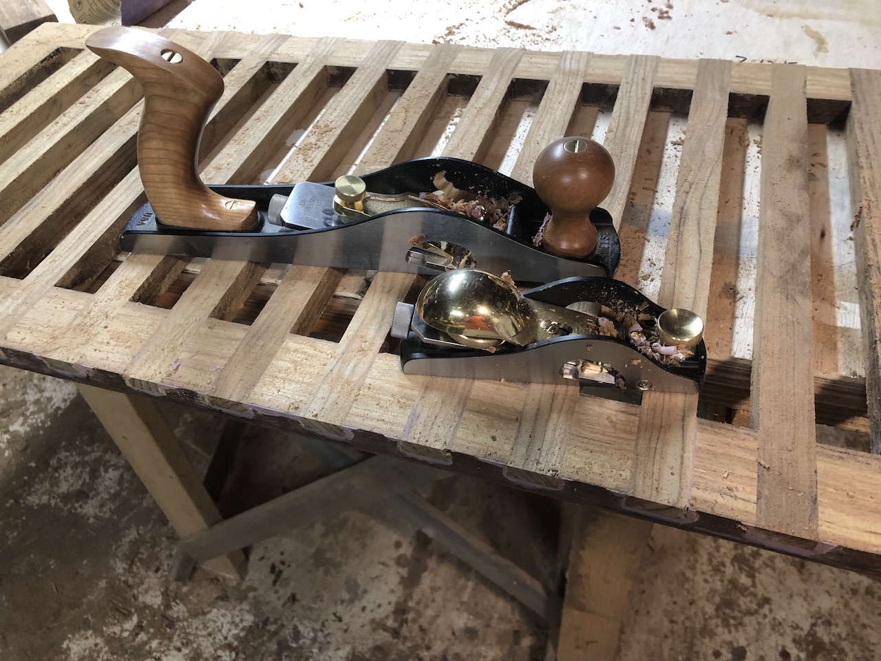
I used the belt sander to remove the dried glue and most of protruding ends of the transverse members.
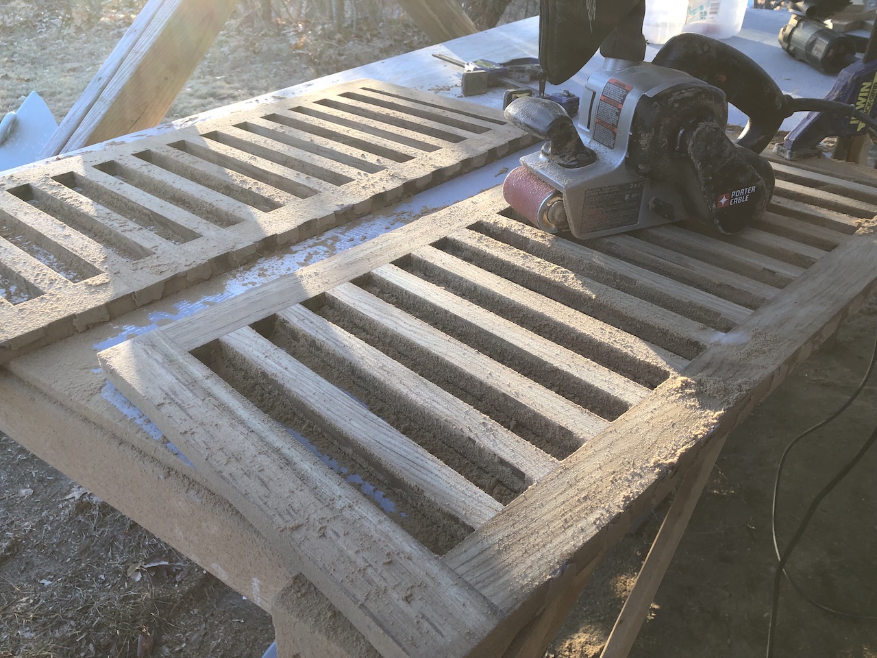
The hand planes did a great job of taking off the rest of the ends.
The following photo shows one of the original gratings and you can see that the longitudinal members are very thin (about 1/8 inch) and set into shallow rabbets with nails. The frame receives the ends in a very shallow rabbet.
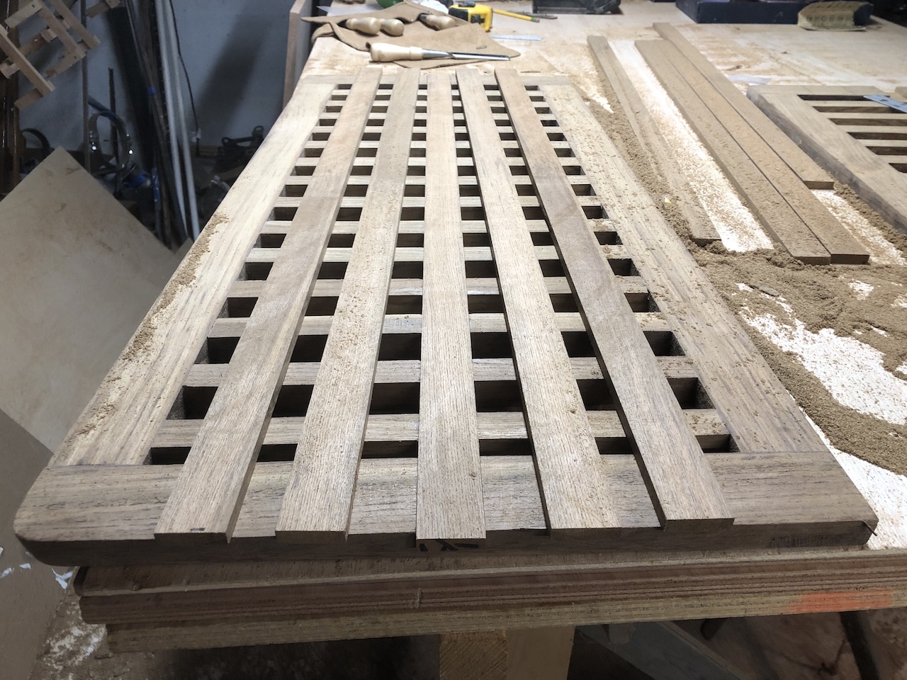
Much of the damage to the original gratings is to these thin longitudinal strips, so I decided to go with much thicker and slightly wider material,
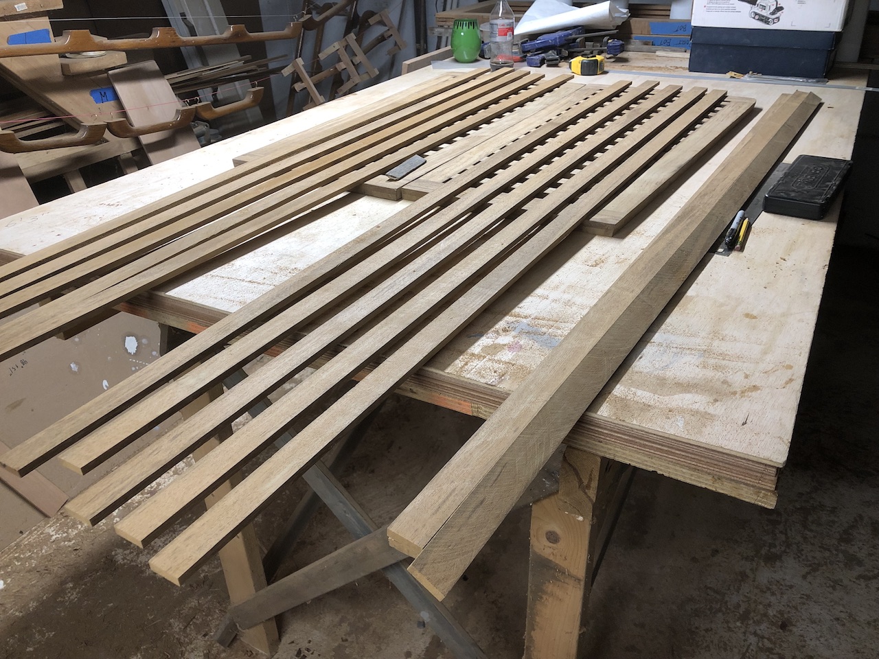
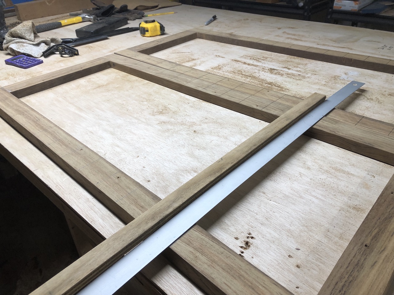
Once again, the gratings are not square, so if I cut the grooves parallel to one edge, then at the other edge the groove will be very noticeably not parallel. My plan calls for five strips, and the outer two on each side will be parallel to the close frame edge, and the middle strip will split the difference and be parallel to neither edge. This was the scheme for the original gratings, and they looked just fine. In the photo below I’ve used the circular saw and a long guide to cut our the center groove in one of the two forward gratings.
Here the center longitudinal member is set into the center row of rabbets, and the other four longitudinal members are simply set on top above their approximate locations.