3/17/19: Cockpit Grating II
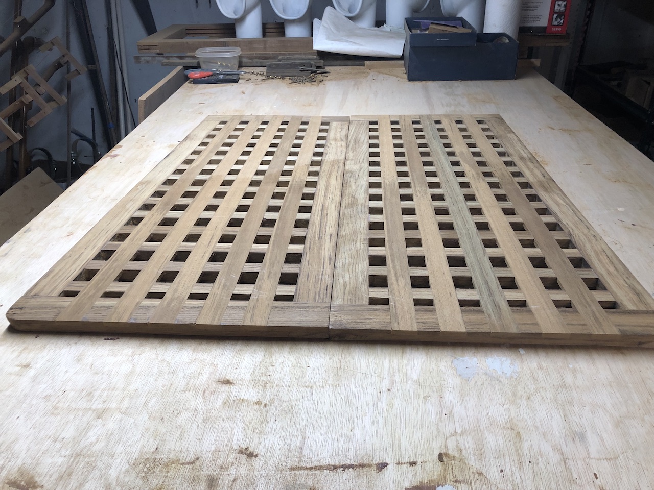
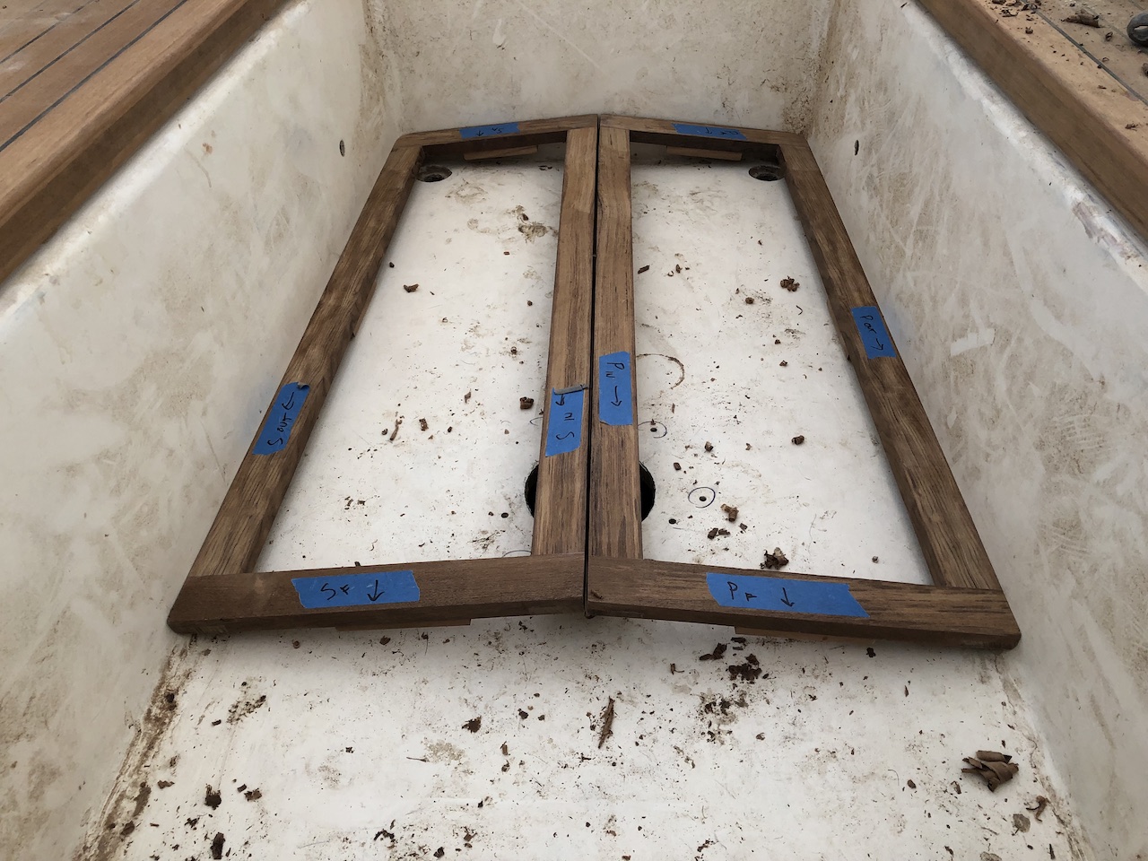
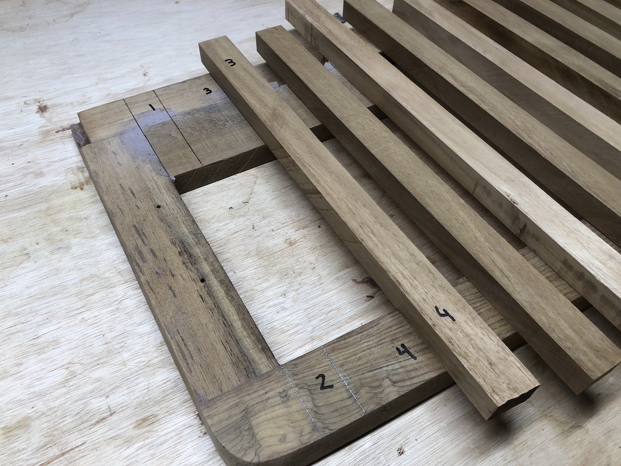
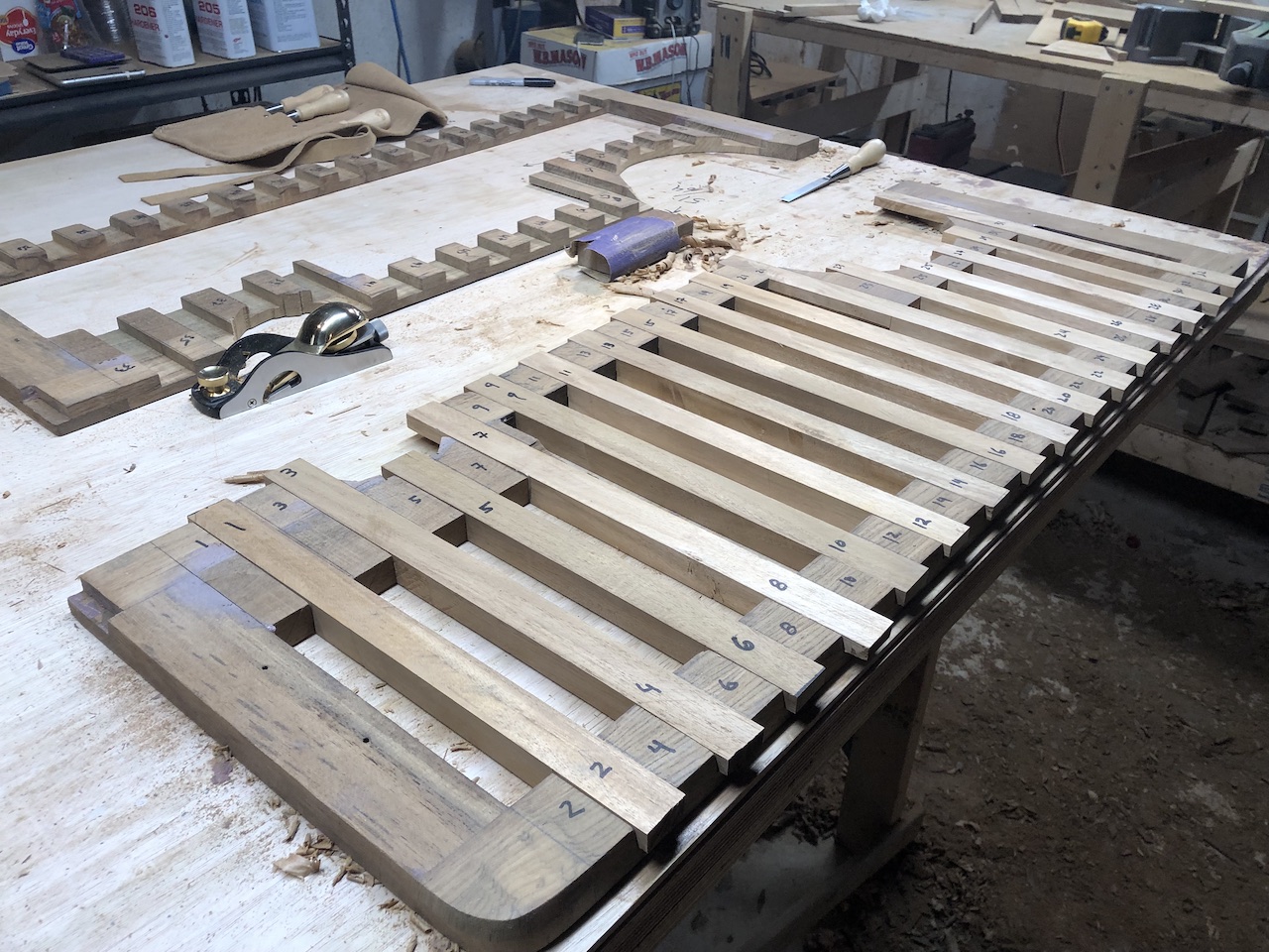
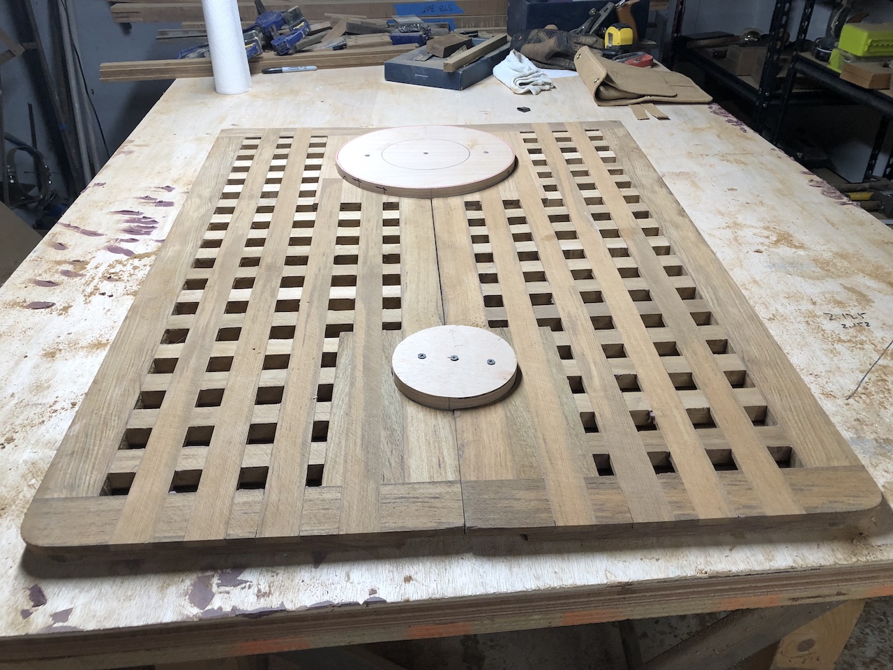
7Work continues on the cockpit gratings. Below, the two forward gratings are ready to accept the longitudinal slats.
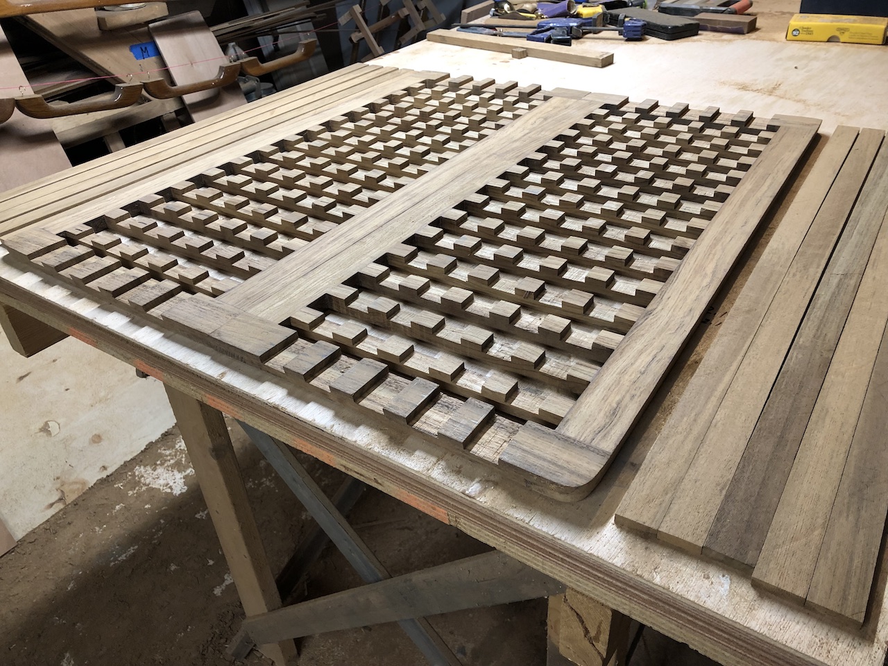
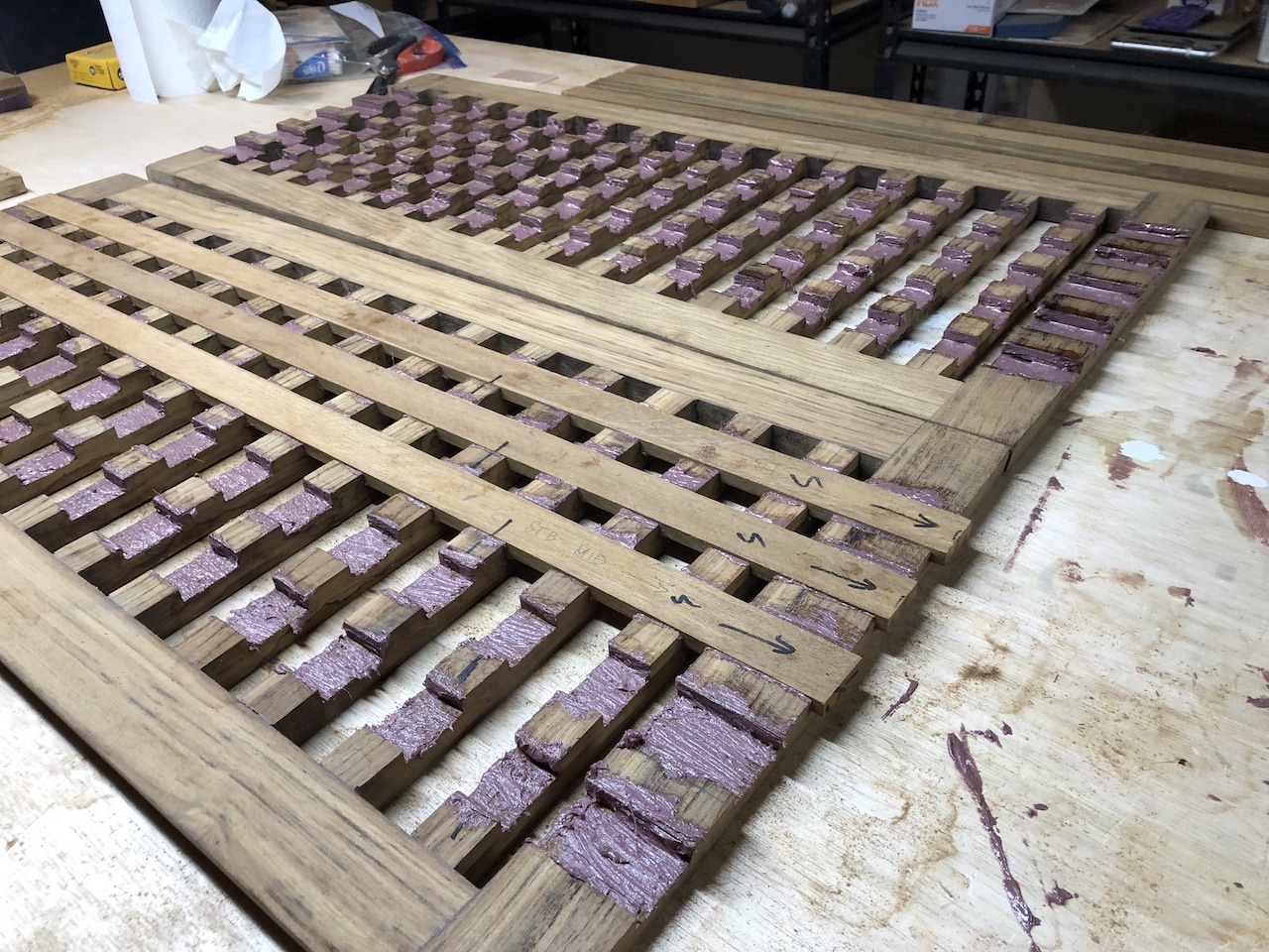
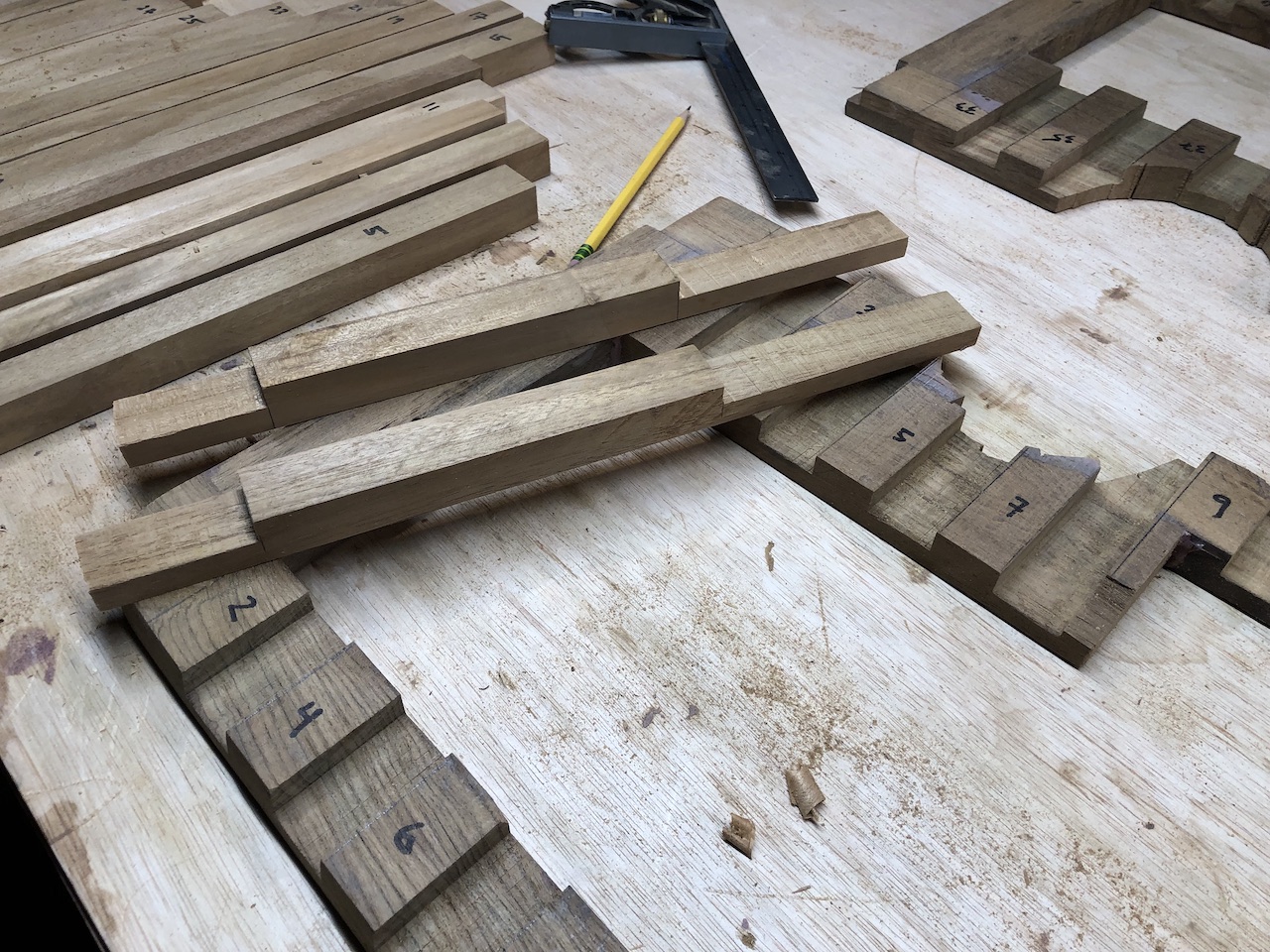
I made marks with a sharpie as a means to easily identify the location and orientation of each slat.
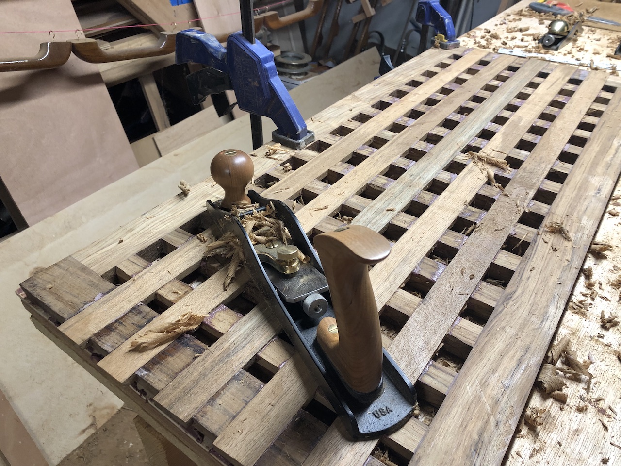
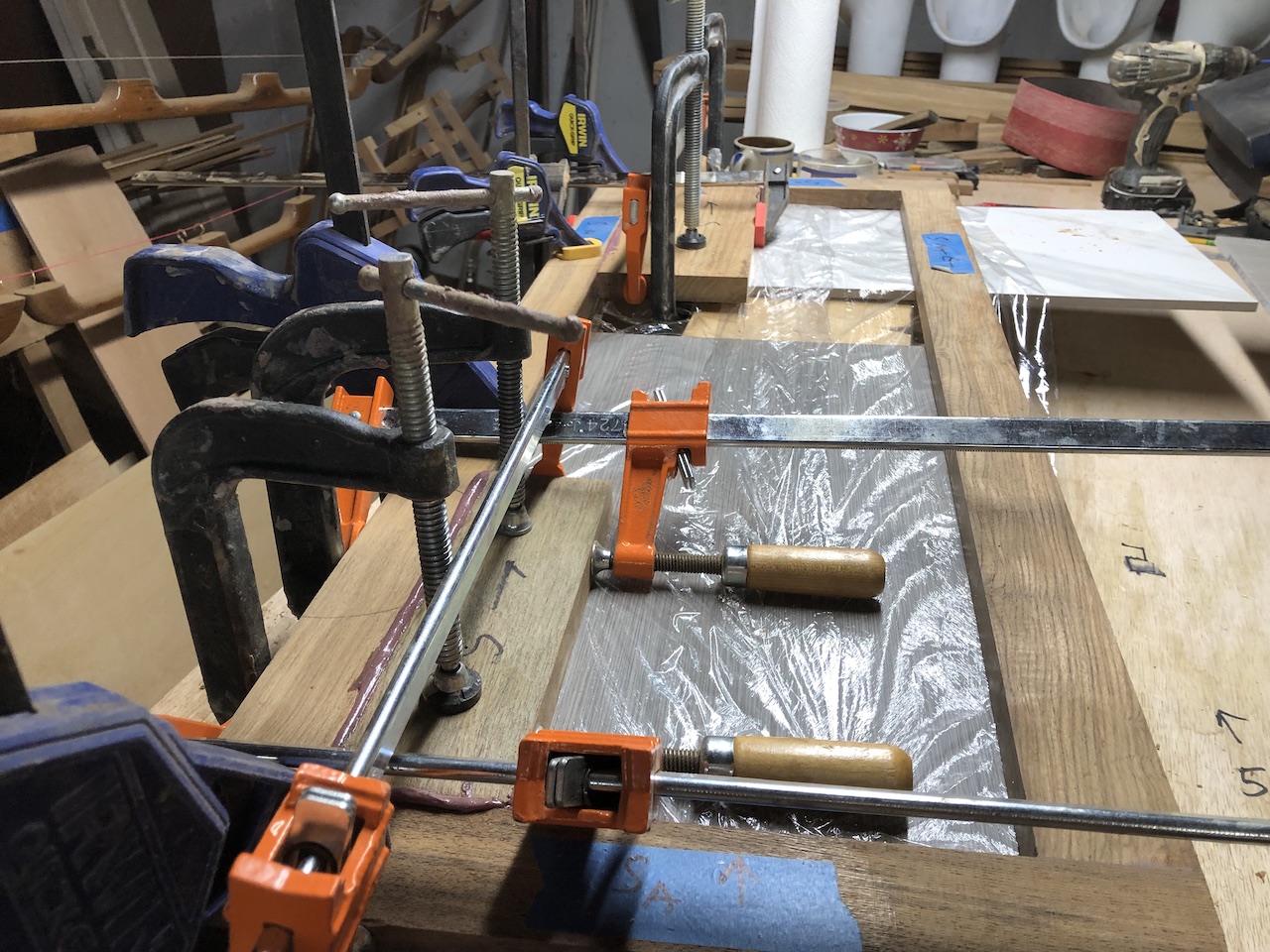
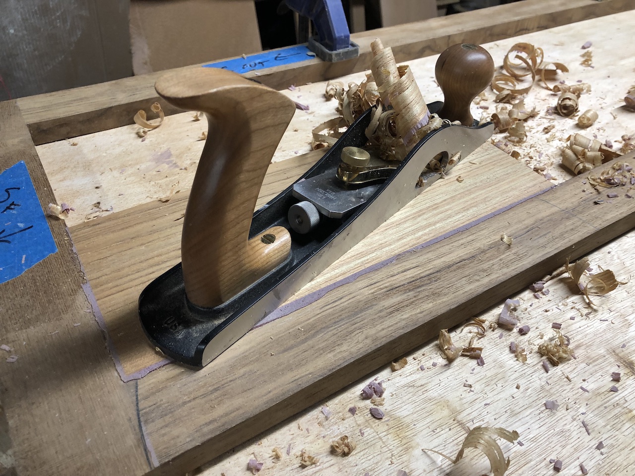
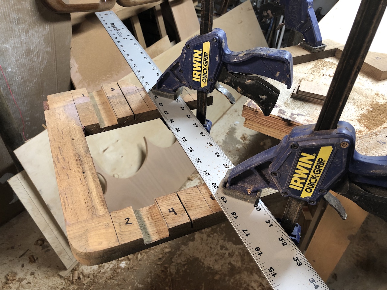
This glue-up job required just a few clamps, and below I’ve removed the clamps and sanded, and am planing the surface flat.
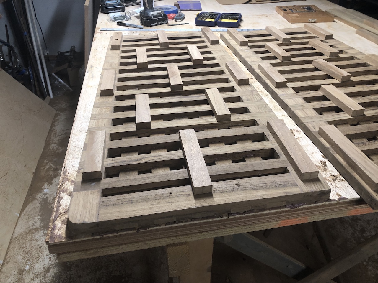
The gratings are supported by a number of narrow blocks that are screwed onto the bottom sides. More on that later.
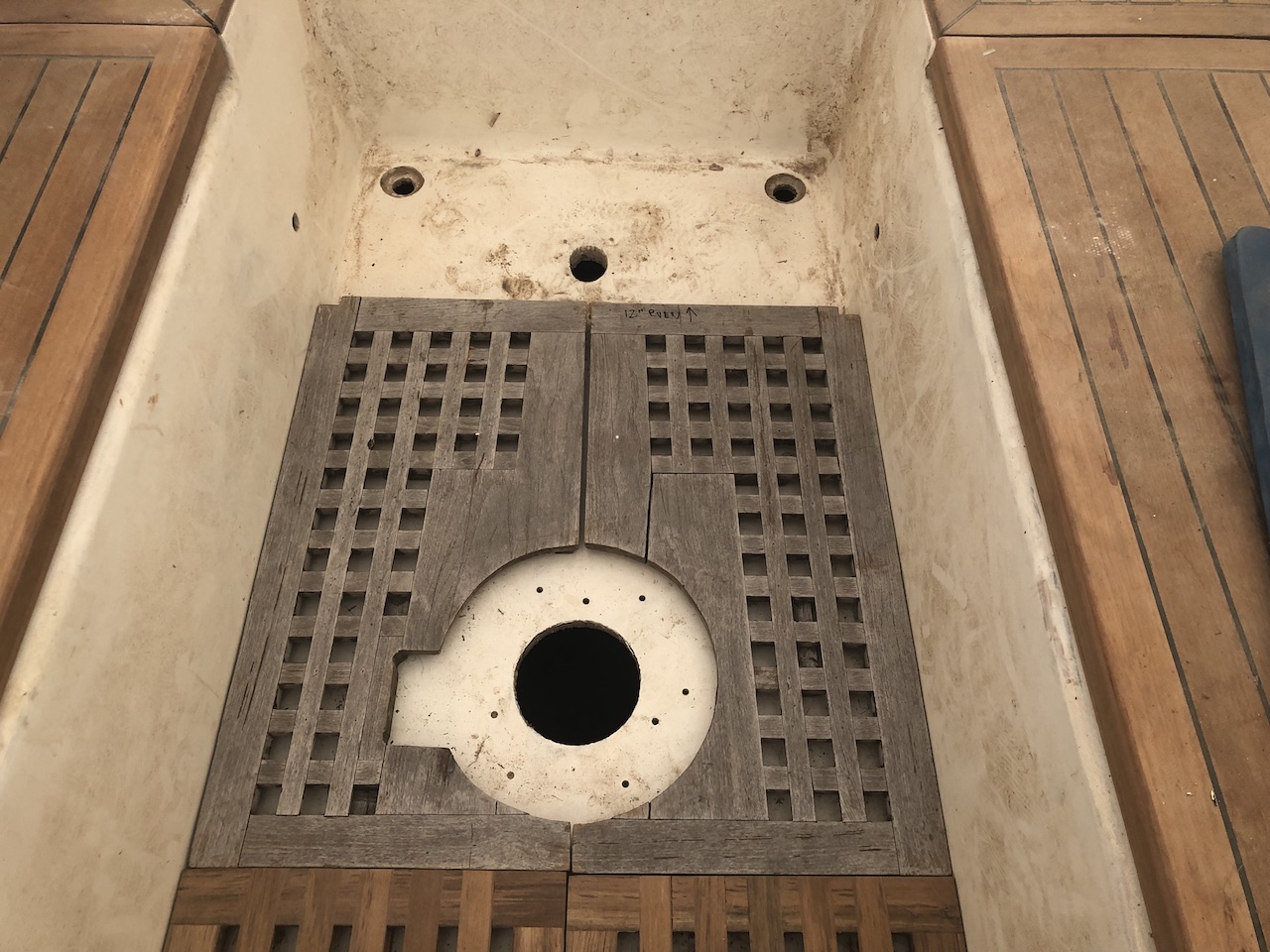
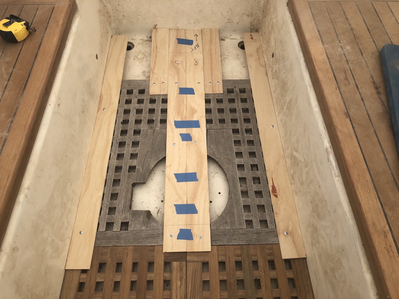
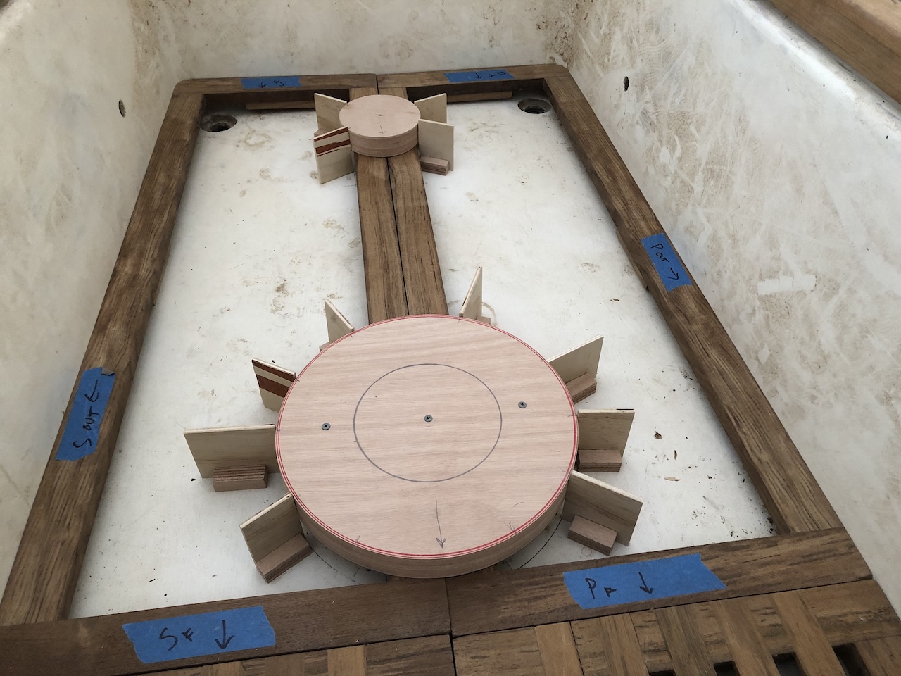
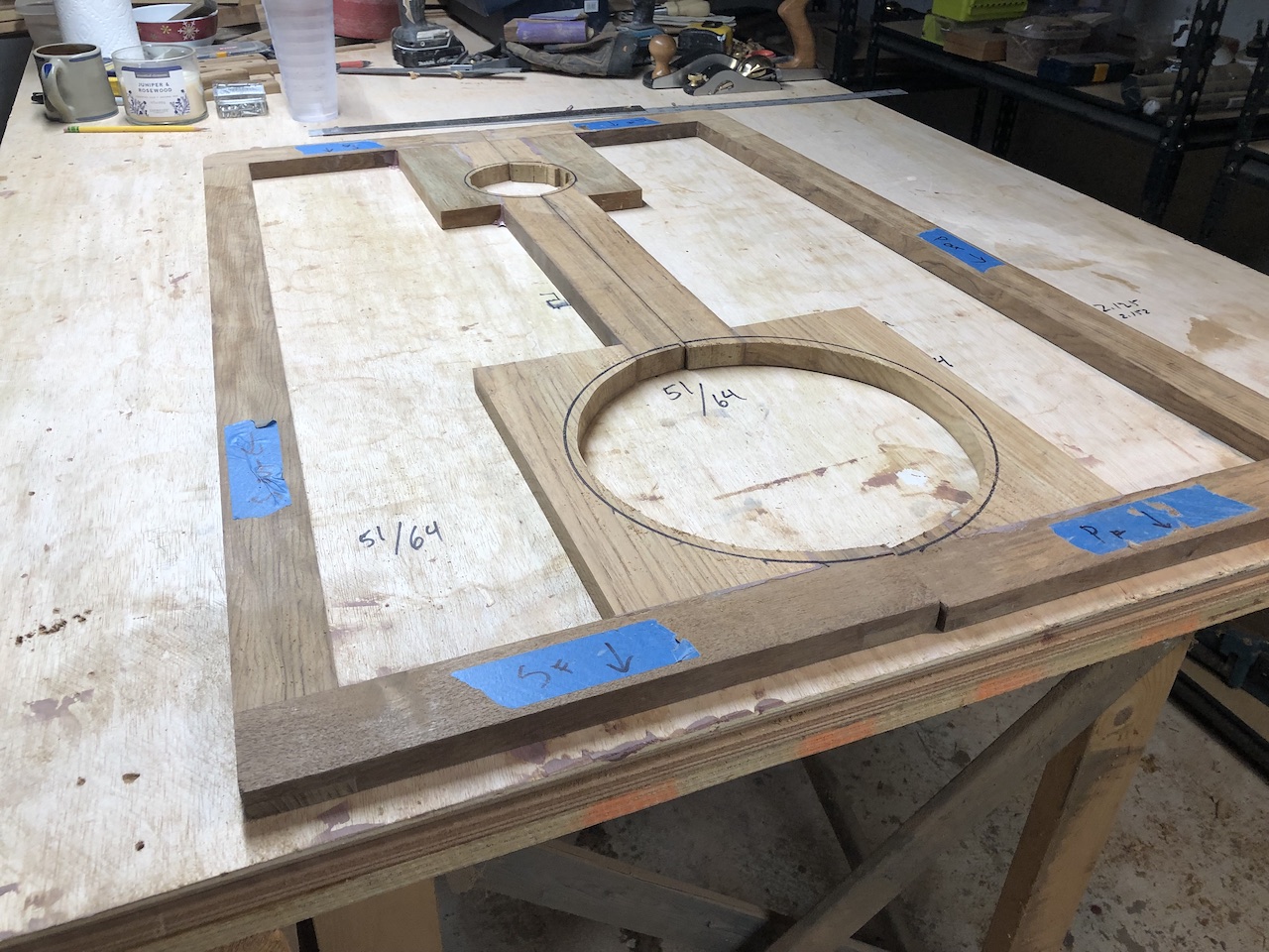
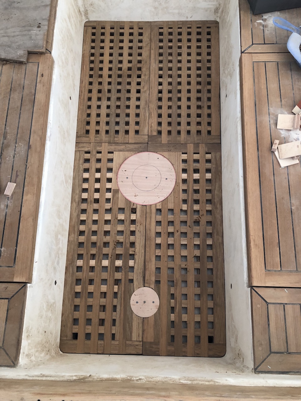
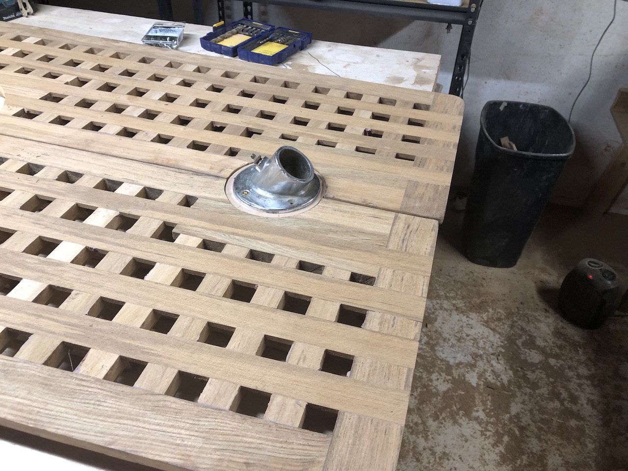
In the photo below I’ve placed the original aft gratings on the cockpit sole. The two aft gratings are more complex because they need holes for the steering pedestal base and, further aft, a base for a fitting that encloses the top of the rudder post.
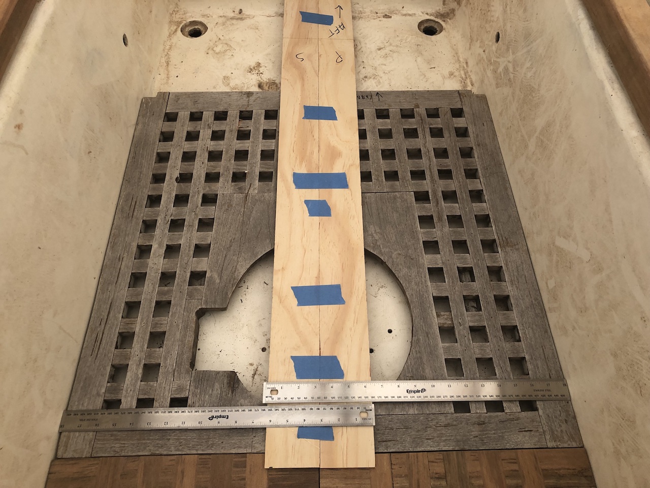
I taped two pieces of template material together and centered them exactly, then screwed them to the original gratings.
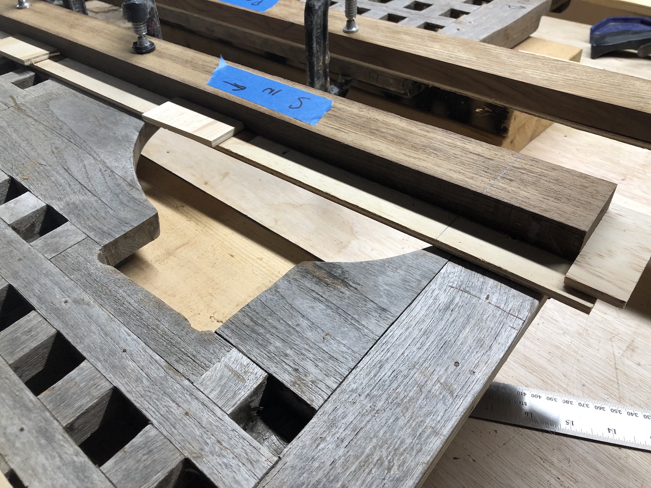
In the workshop, I positioned the new trim pieces, then glued some small pieces of template material against the pieces as a means to be able to position them precisely after removing them to cut the joints.
Fast forward a little, and the trim is glued up with the usual half-lap joints.
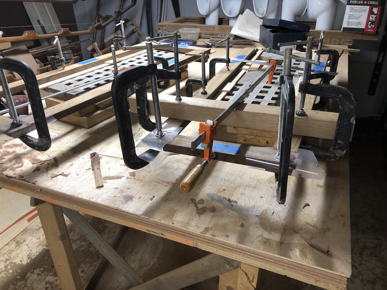
Out of the clamps, sanded, and edges beveled to match the slope of the cockpit sides, there was still some material to remove, which I did with a block plane.
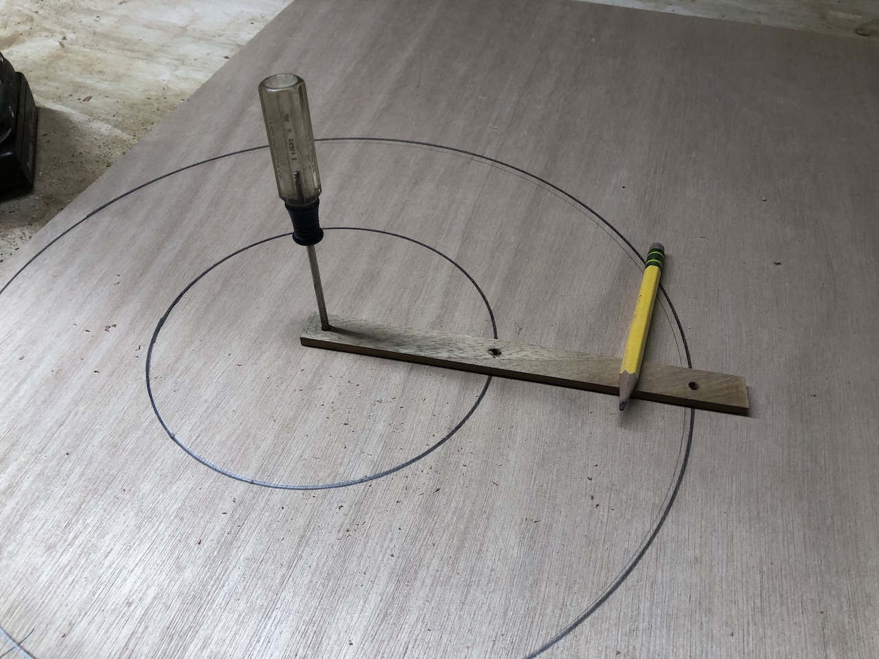
I measured the diameter of the base of the original steering pedestal, and also researched the specs of possible new steering pedestals.
It turns out that a 12-inch diameter base would be sufficient.
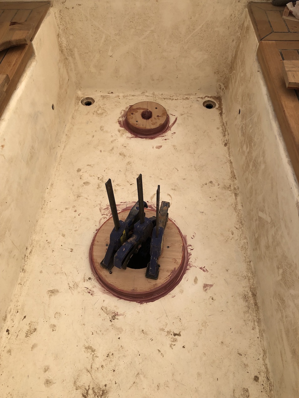
My next task was to determine the positions of the two bases, then transfer the positions to the frames. The challenge here is that the bases and the frames cannot be simultaneously in their correct positions, so I hot-glued some blocks and strips of wood to the cockpit sole.
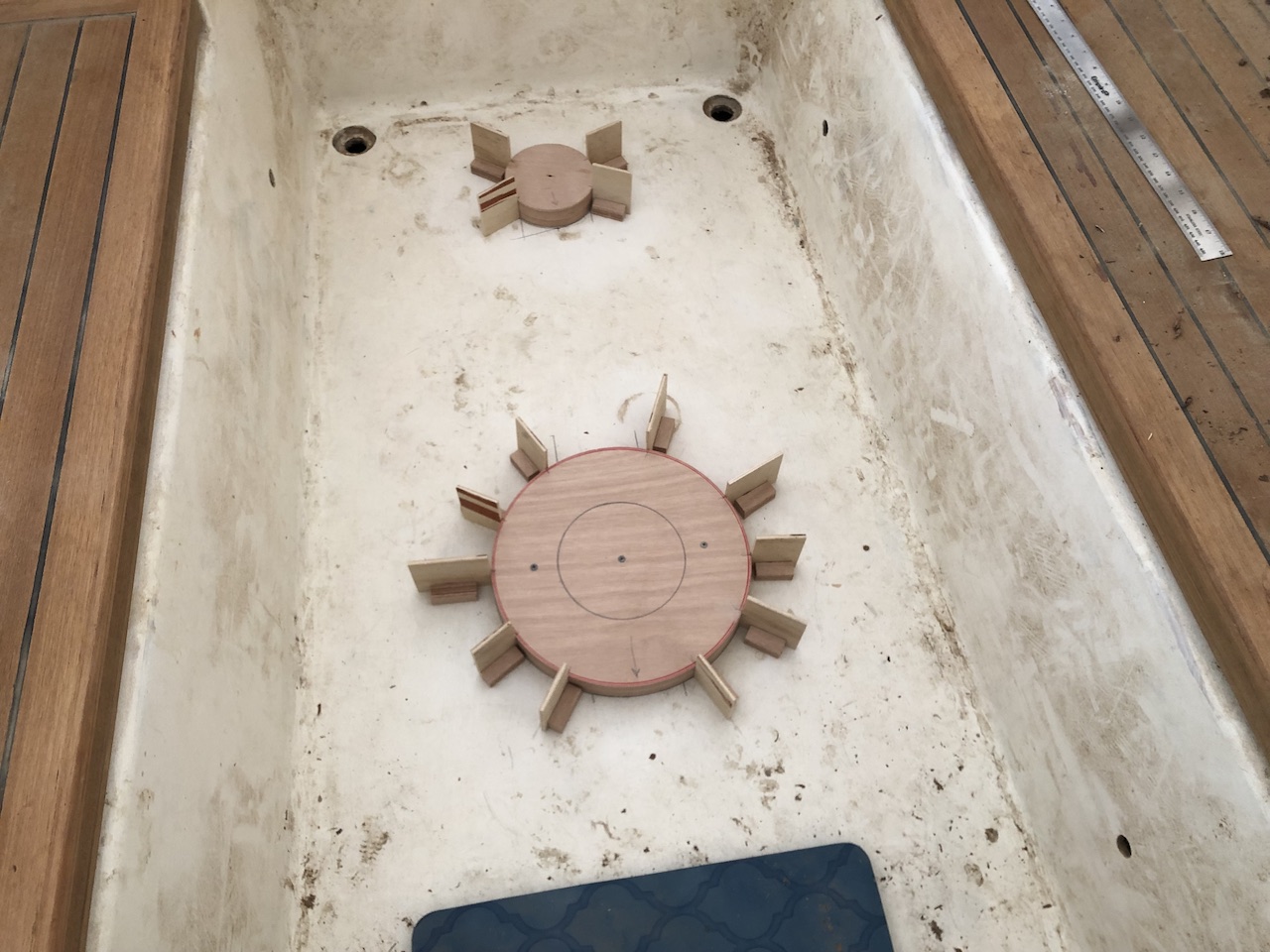
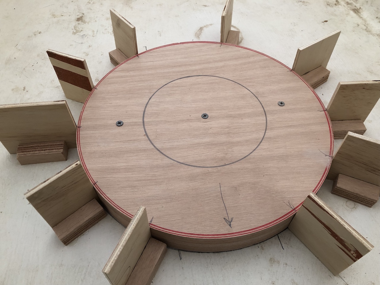
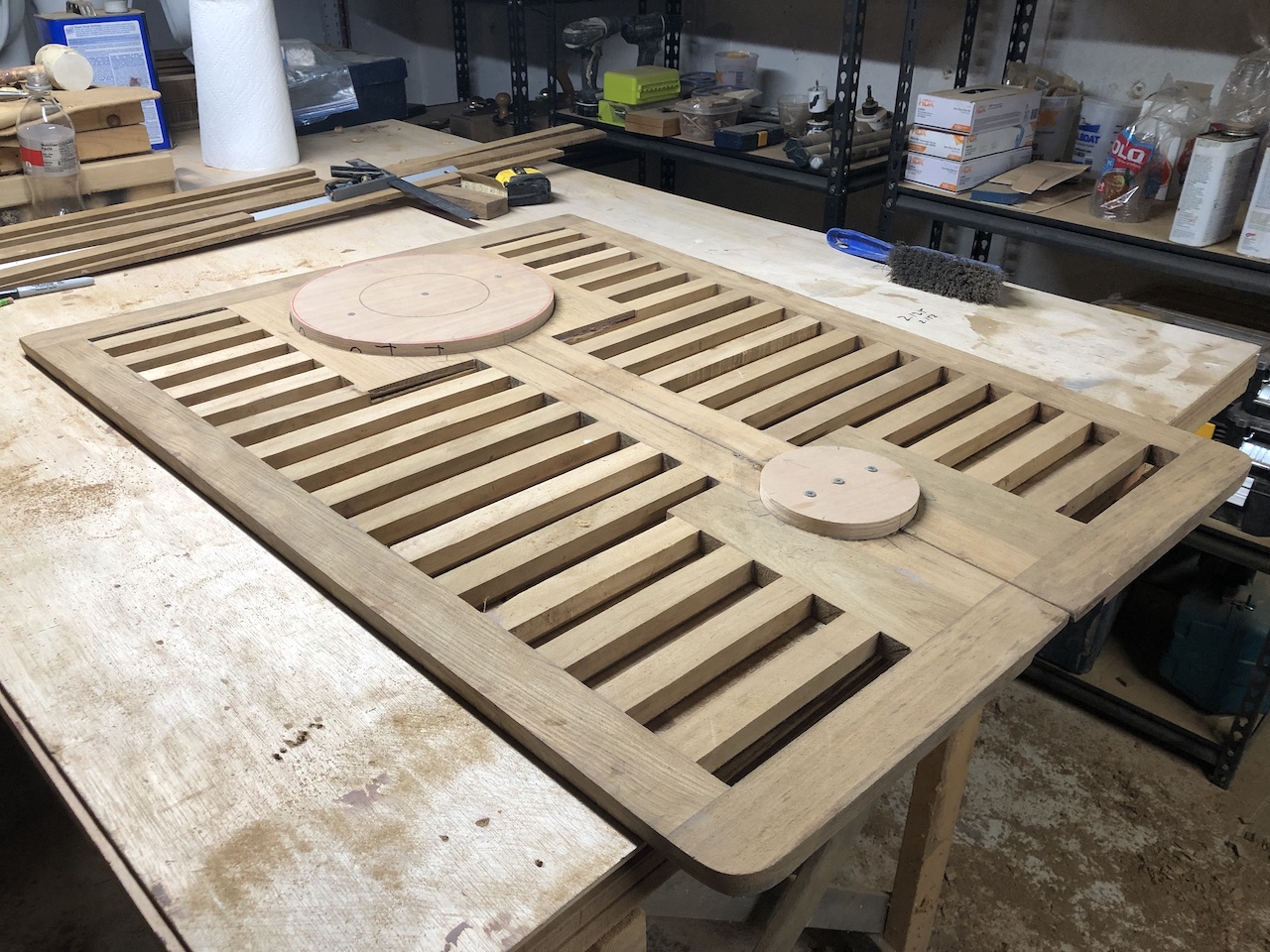
Doing so allowed me to find the correct location to trace the circles onto the frames.
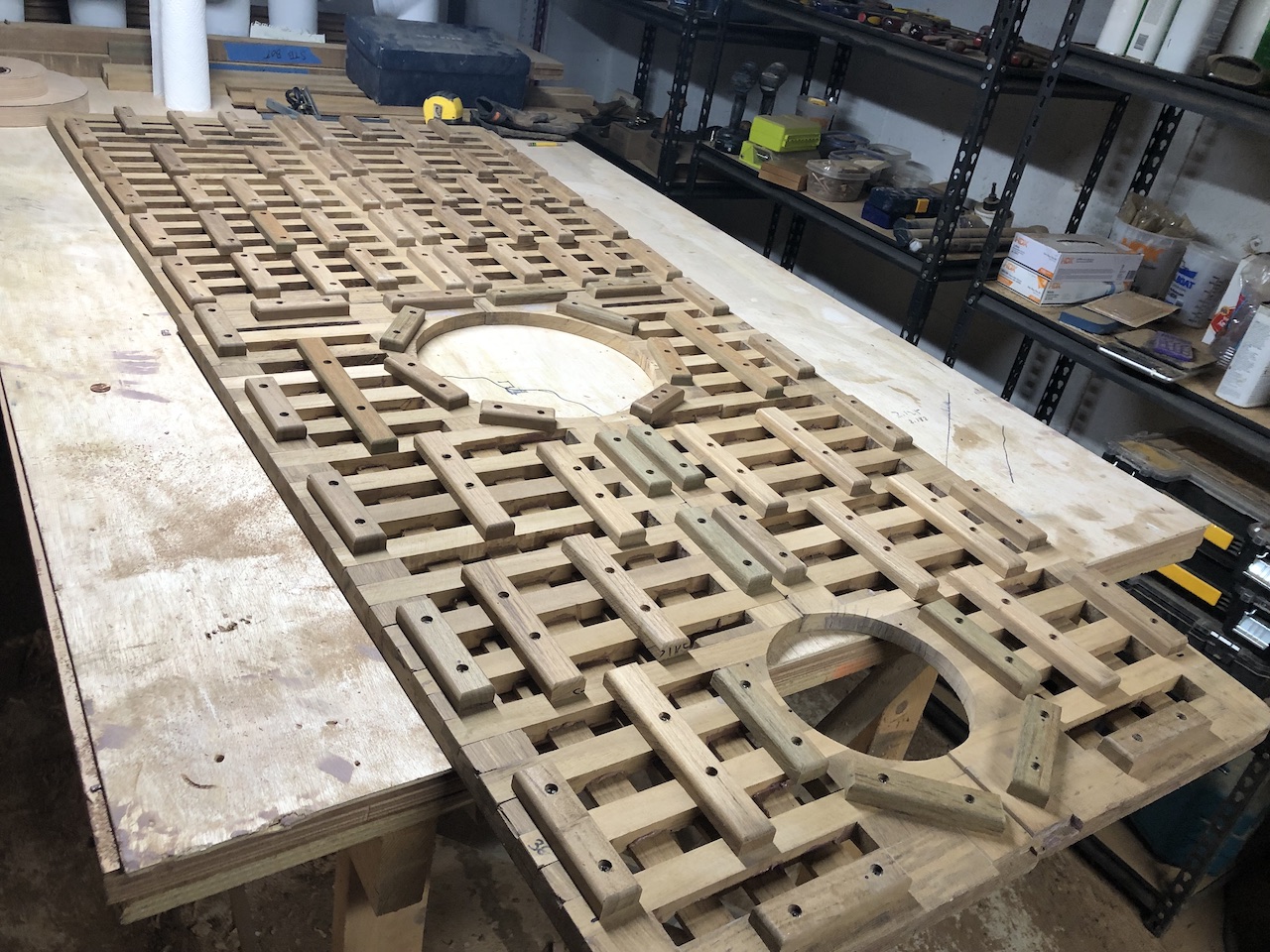
I wanted solid wood around the bases, so I glued in some solid teak in four locations.
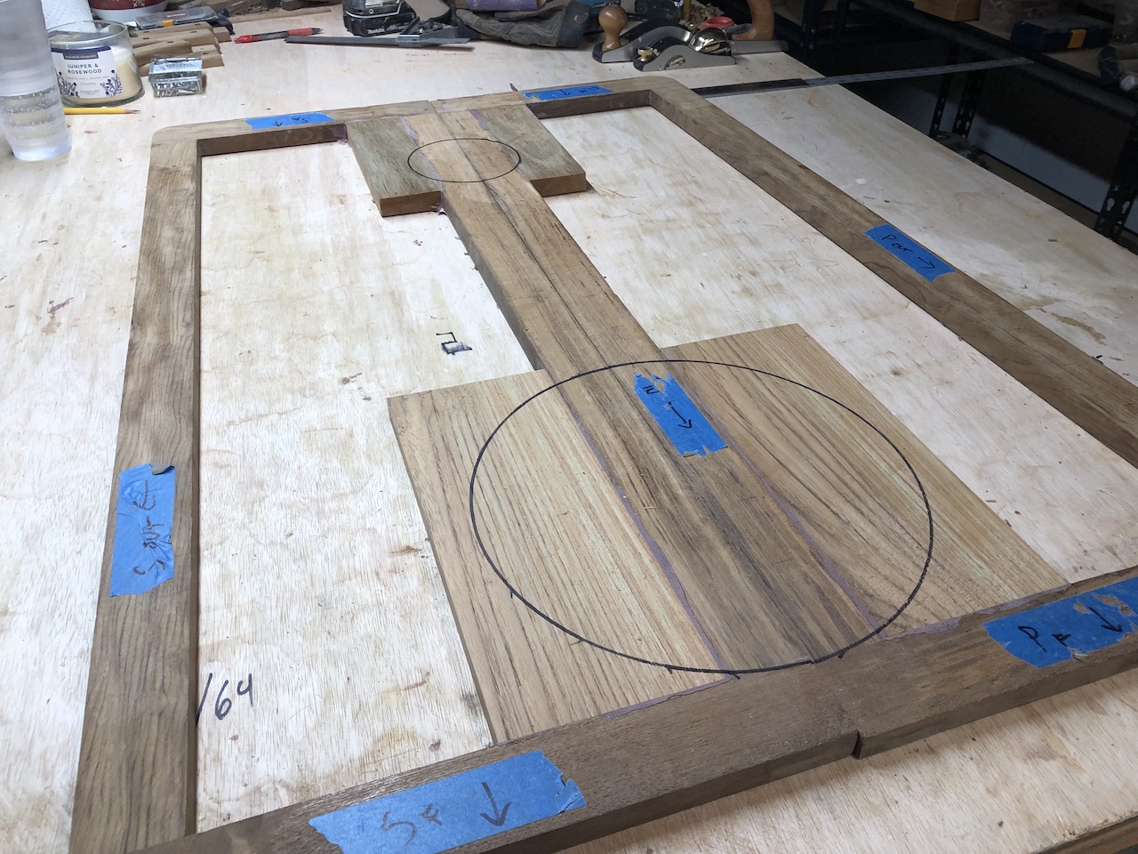
I cut the circles well inside the trace.
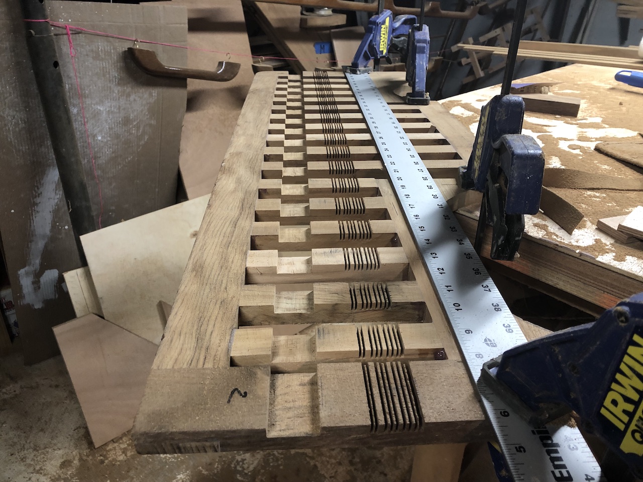
Next, I planned the layout of the transverse members.
Once again, running the circular saw along a movable fence proved a suitable method to hog out most of the waste.
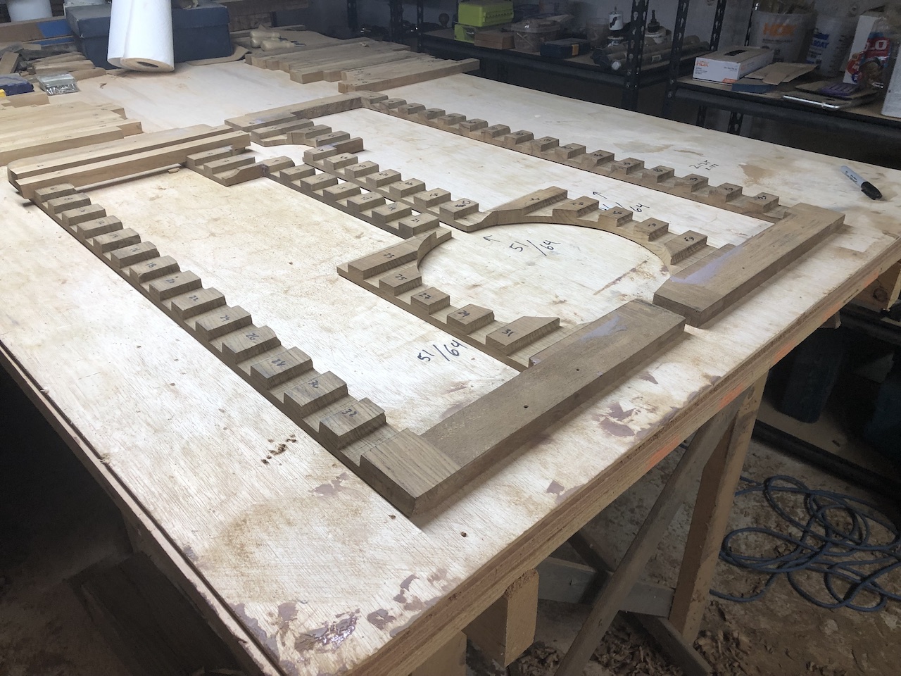
Once again, I used the table saw with the stacked dado blade and the miter saw to remove the waste from the transverse members.
Here is a dry fit of some of the joints.
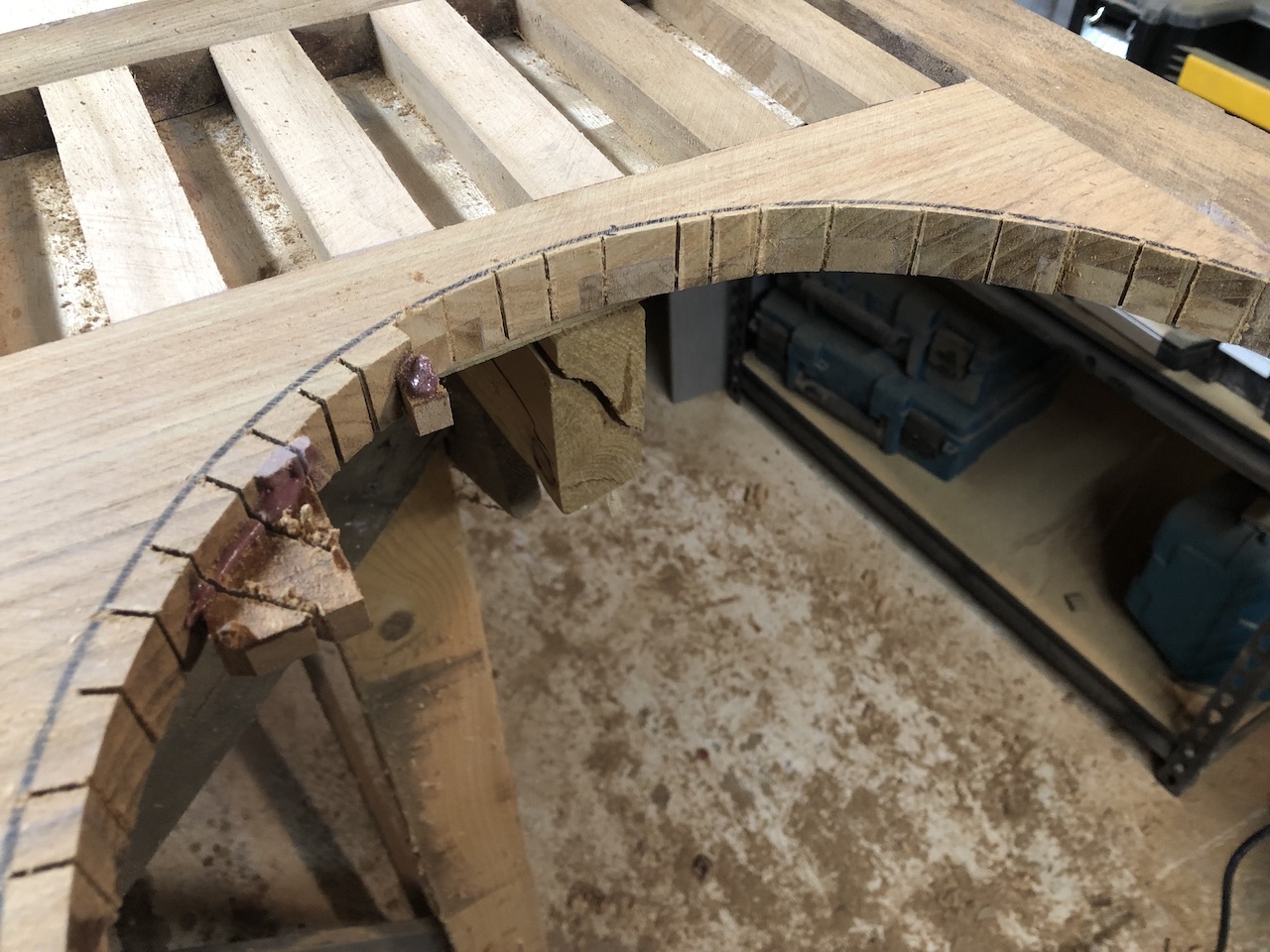
When cutting close to a curved line with a jig saw, it’s helpful to start with a number of relief cuts, perpendicular to the line.
After some sanding, the bases fit just right.
On to the longitudinal members:
The system of support blocks was planned so that water can run relatively freely to the cockpit drains.
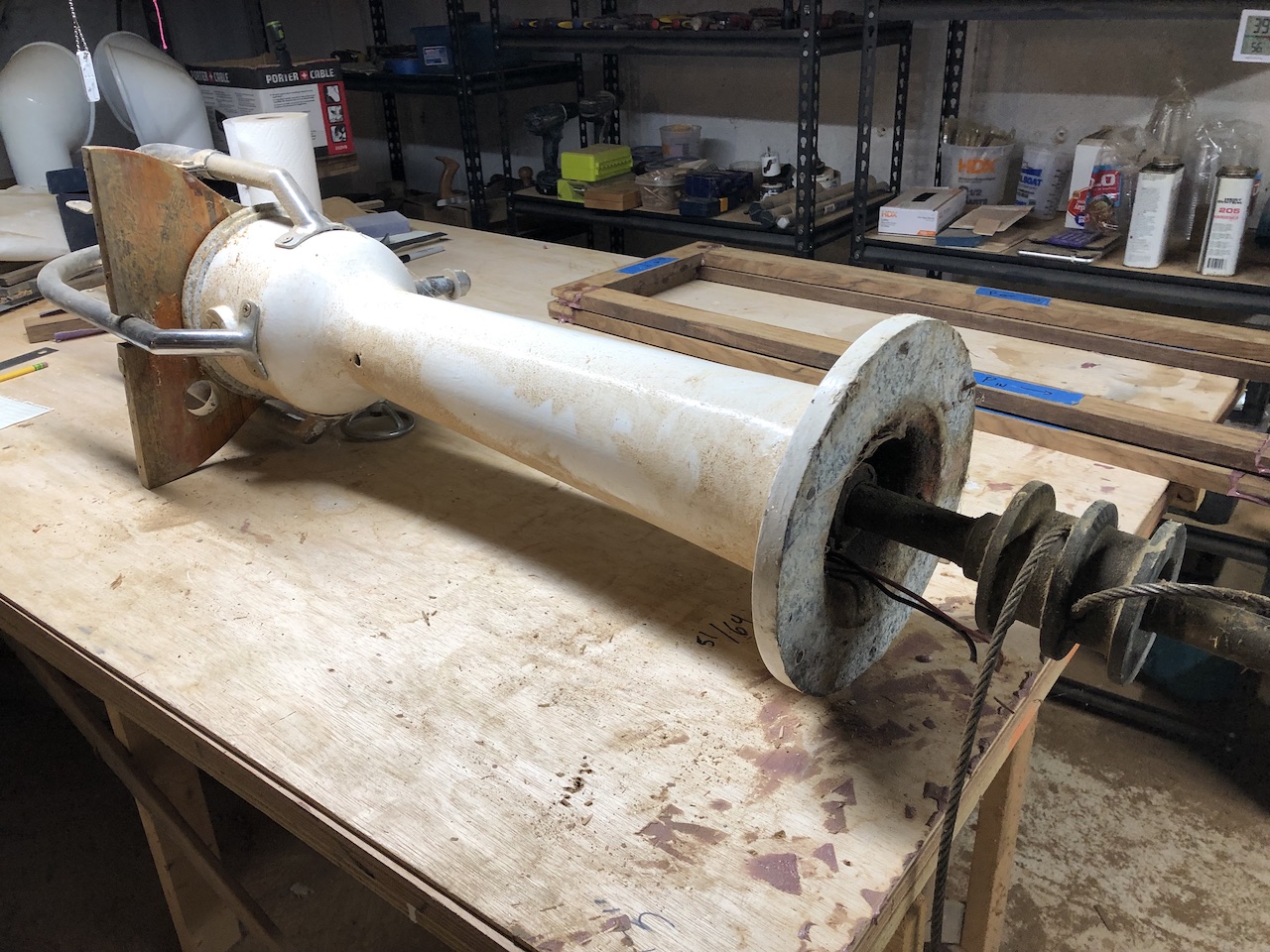
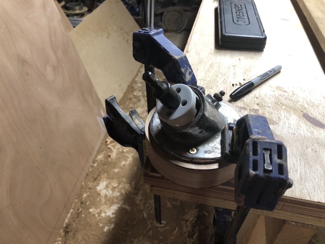
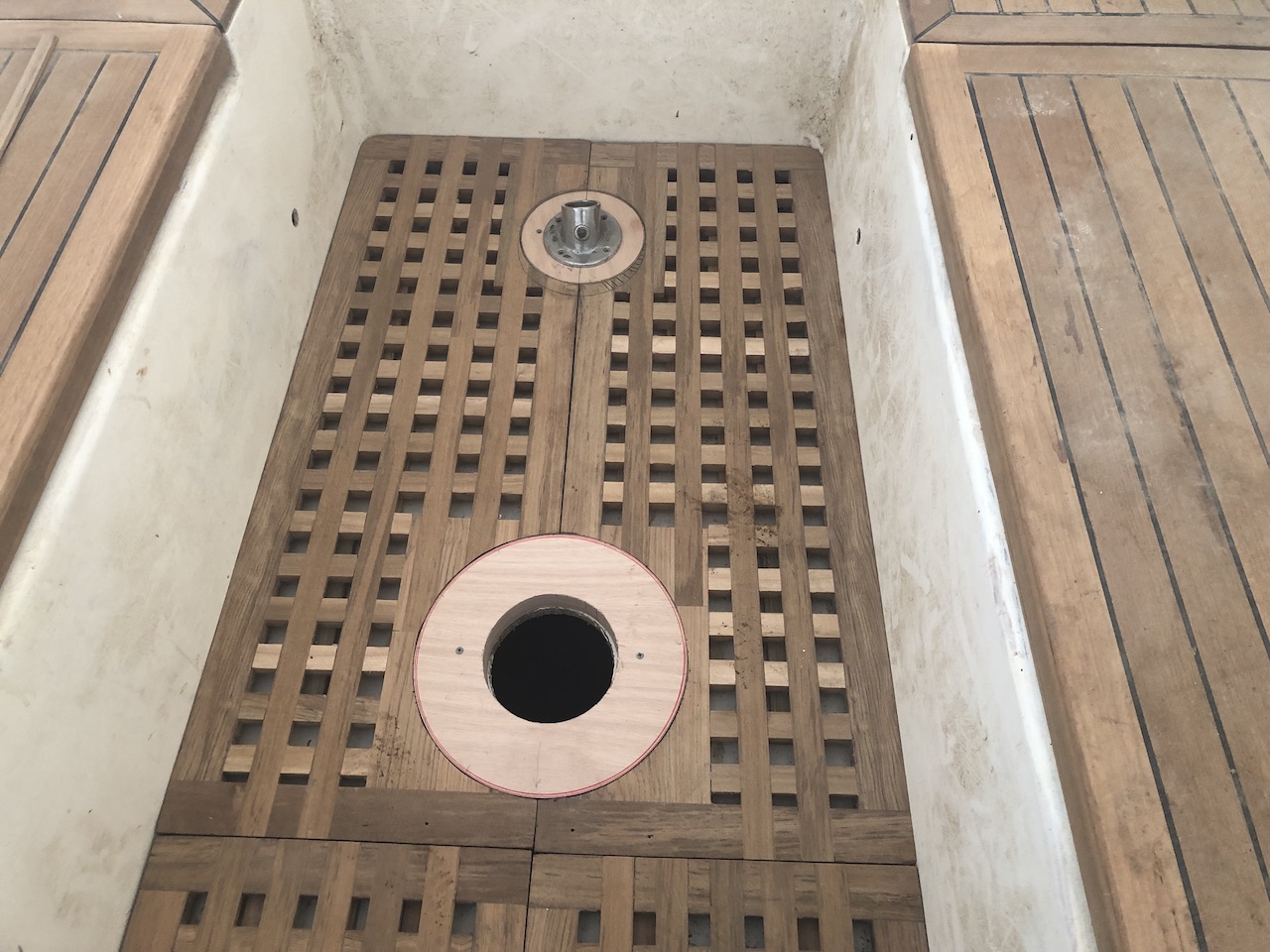
I found the fitting for the top of the rudder post.
I used a hole saw to make an opening at just the correct angle.
I had forgotten how steep this angle is, and found that I needed to move the base about 1 inch aft.
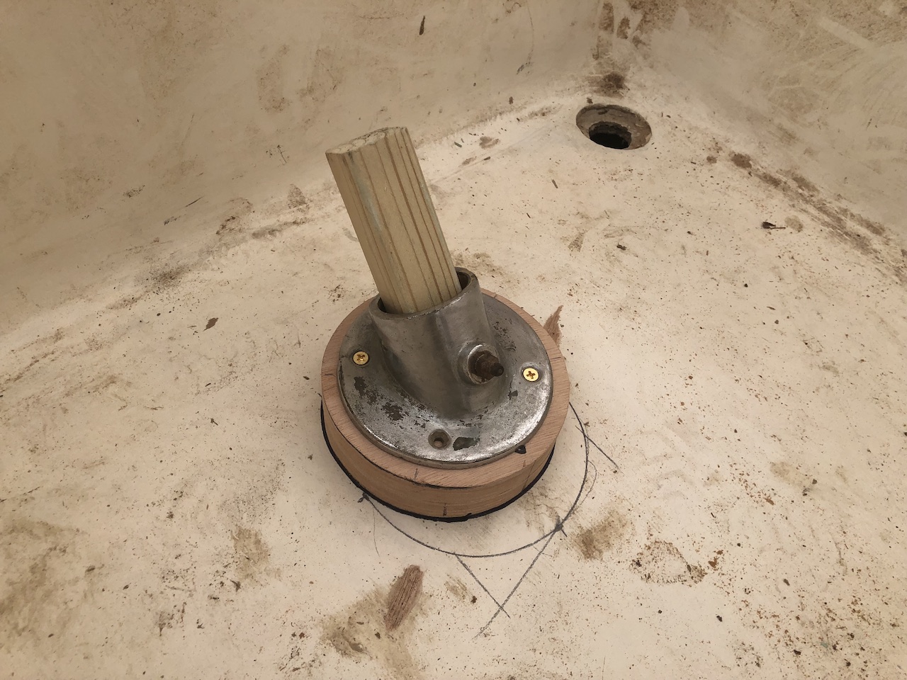
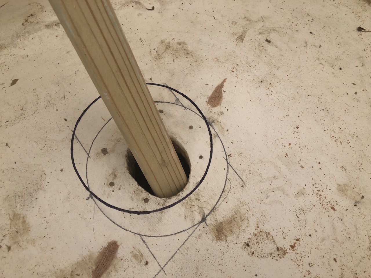
The easiest fix was to simply make a base of a larger diameter, and retrace and cut the hole in the gratings. Here is that long story, short:
Next, I glued up the bases…
…and one day later sanded, and made a final check for fit.
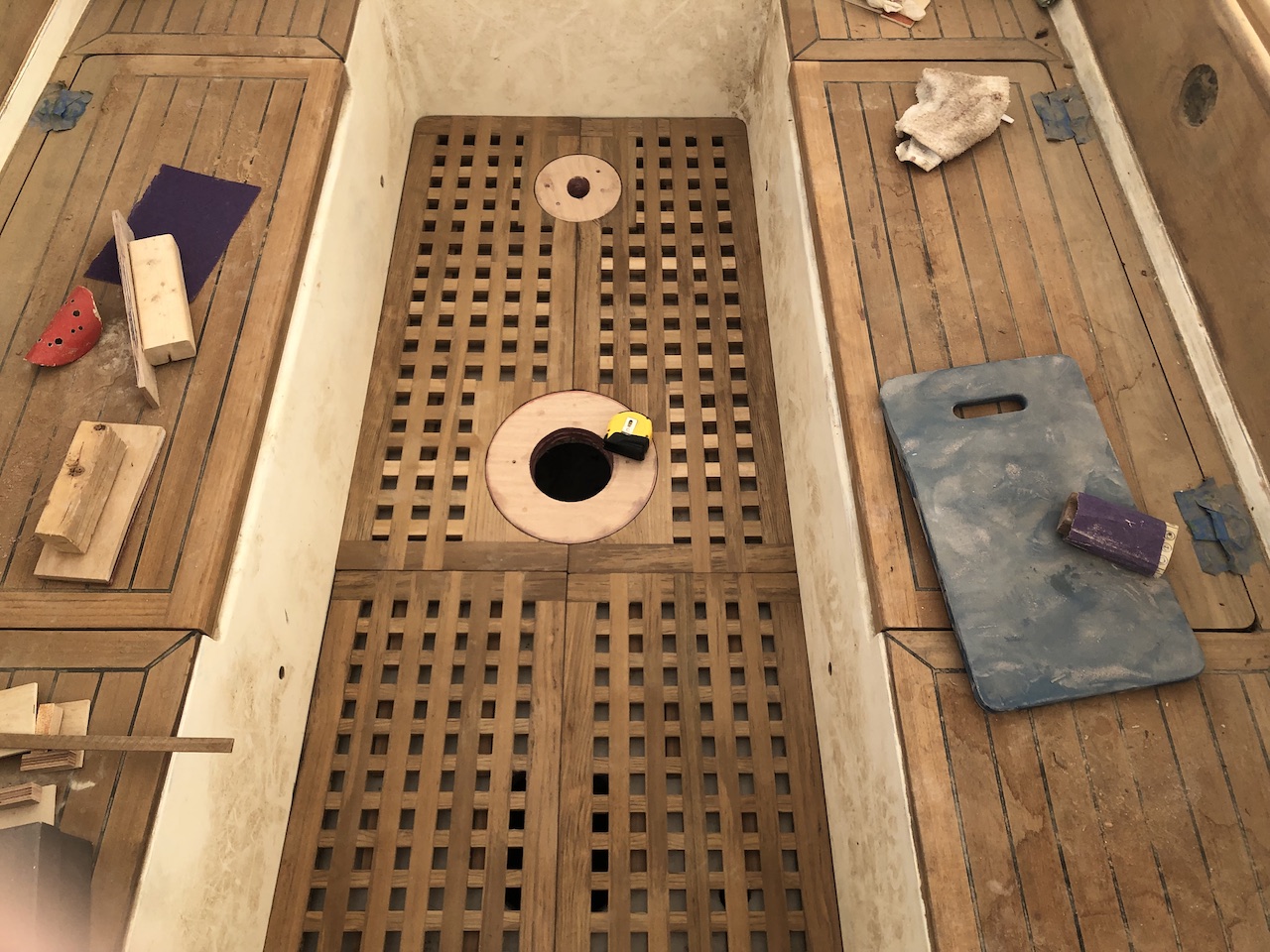
Finally, the cockpit gratings can be moved to storage.