11/10/19: Rudder, Exhaust
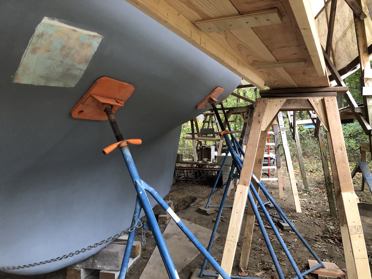
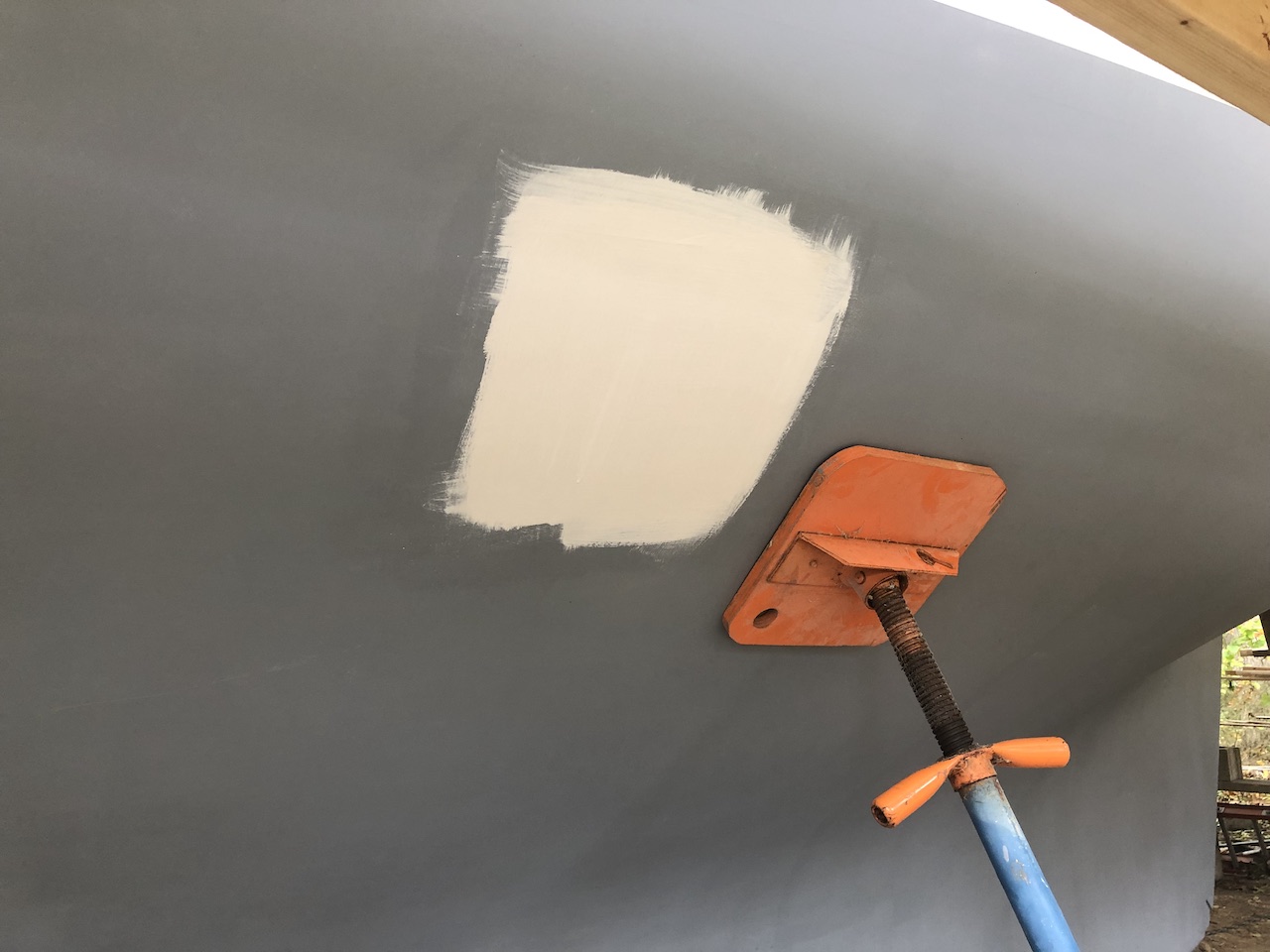
Wrapping up the bottom project required painting under four jack-stand pads.
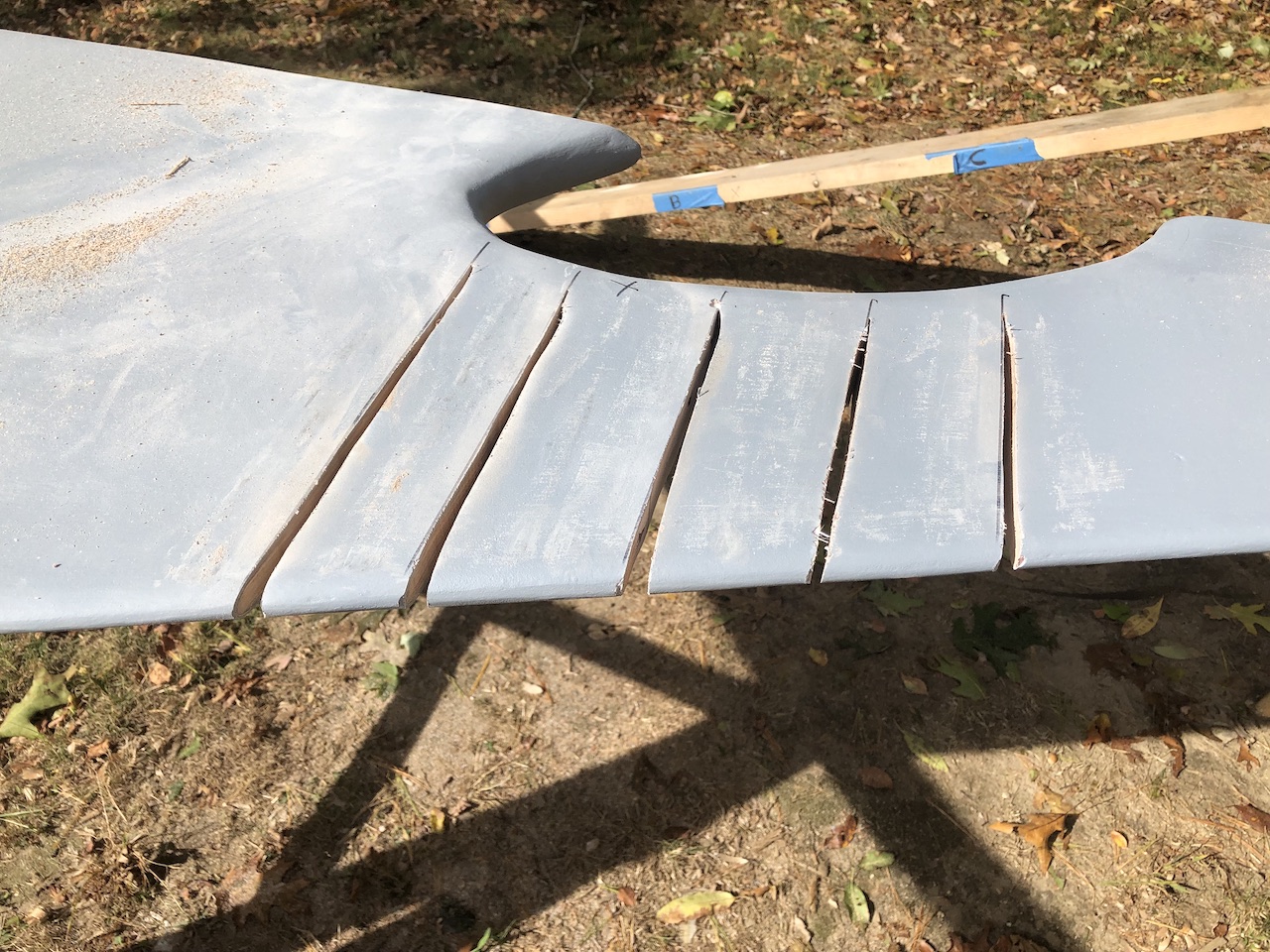
The misalignment of the upper and lower rudder posts persists–despite previous efforts to bend the rudder back into shape. (See HERE for a review.) The boat will steer properly, even with the misalignment, but I decided to make one more effort to fix the problem. This time, I cut grooves into the rudder adjacent the curved section, which is the source of the misalignment.
I constructed yet another bending jig, and then bent, then unbent, then bent, and so on until I felt more bending would not be productive.
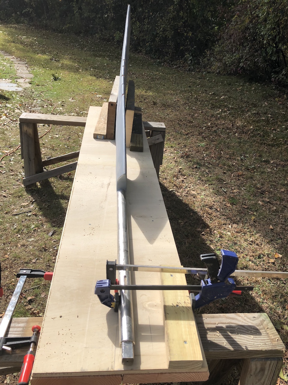
My plan now is to reinstall the rudder with the cut grooves, then repair/glass the rudder while it is in place.
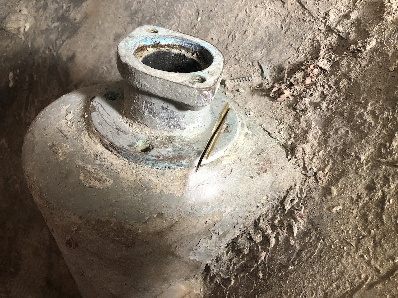
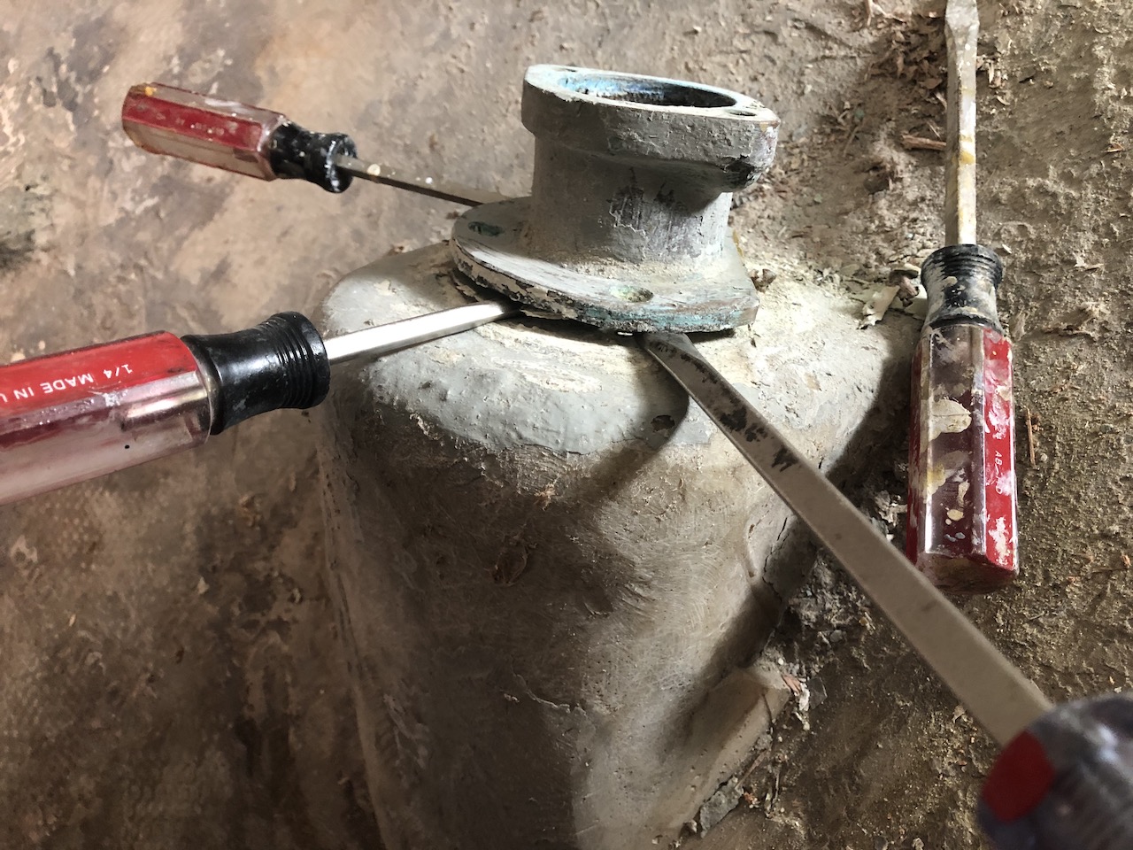
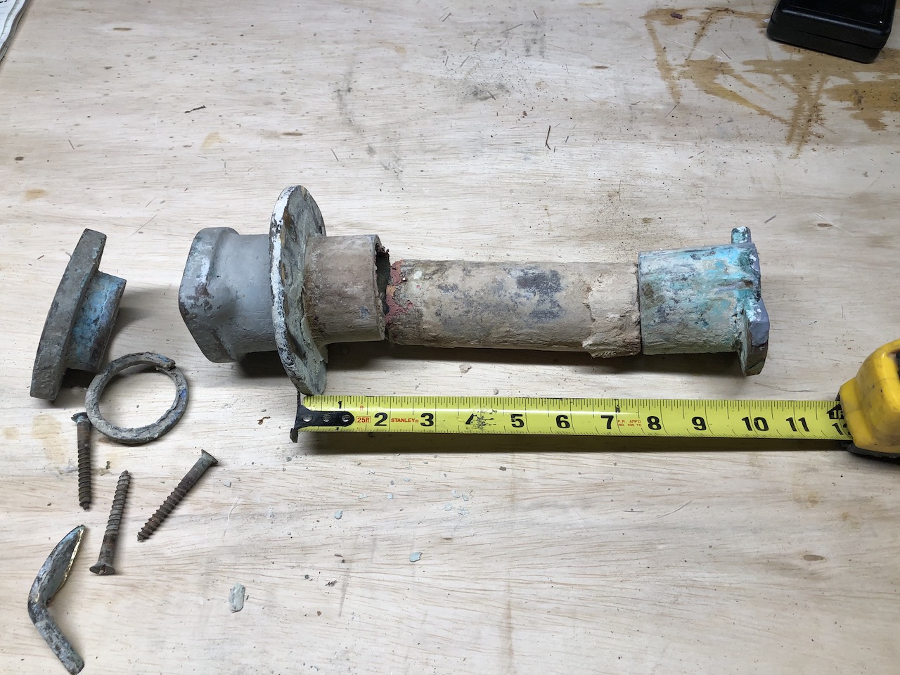
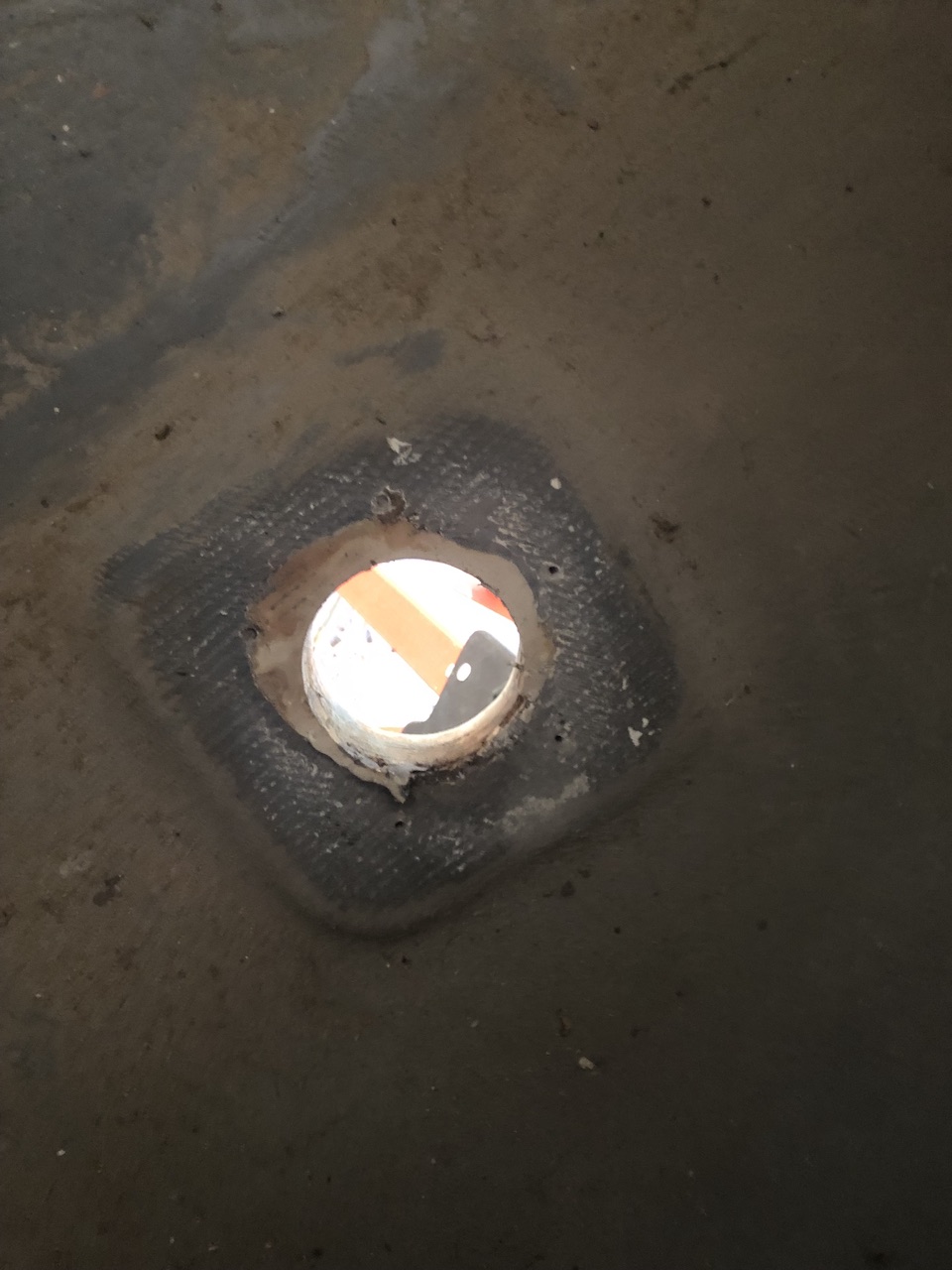
The rudder port serves a dual purpose. First, it is a bearing that holds the upper rudder post in place. Second, there is a flax seal that prevents sea water from entering. After some deliberation, and advice-seeking, I decided to replace the rudder port. The rudder port is under the aft end of the cockpit sole. Three of the four screws came out easily, and one did not, so I did some cutting.
The stubborn screw came out afterwards with pliers.
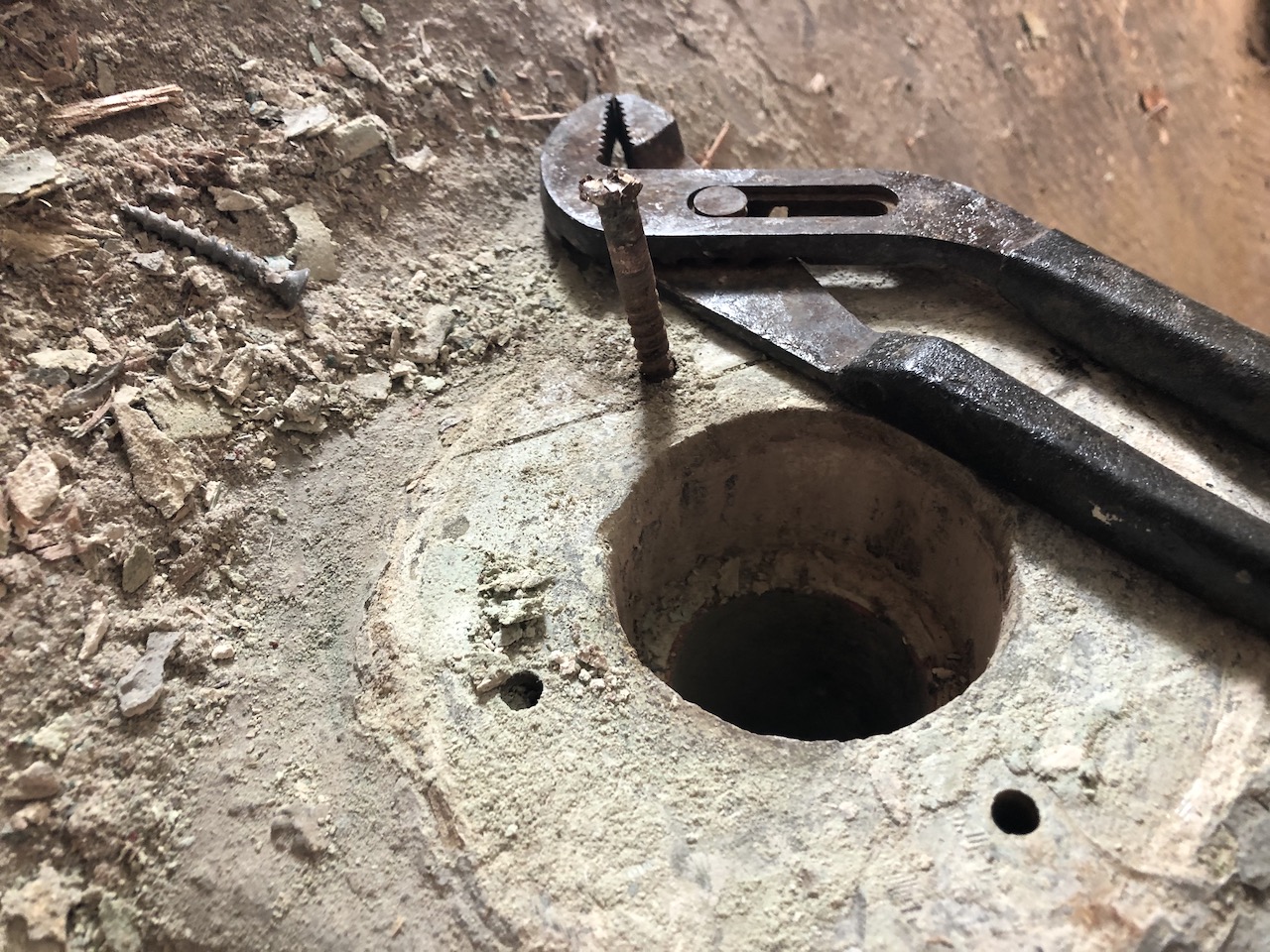
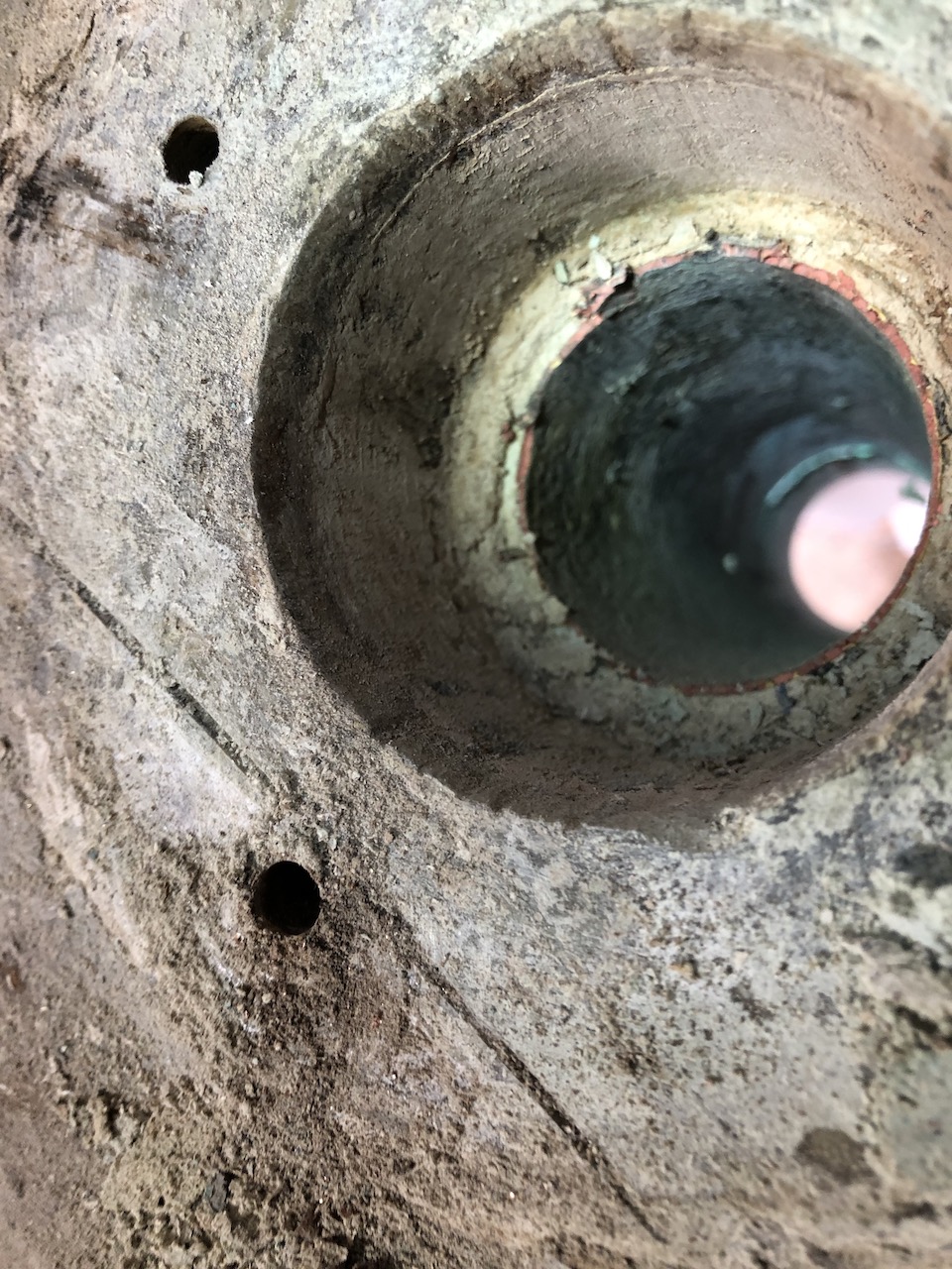
Looking down, there is another bearing inside.
On the bottom end there is yet another bearing, and I applied some heat to hopefully soften any bedding compound or sealant.
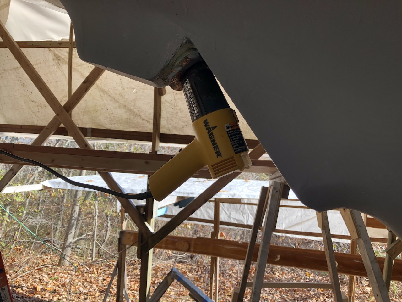
After a few hours of heating, banging, and prying, I had the whole assemble on my workbench.
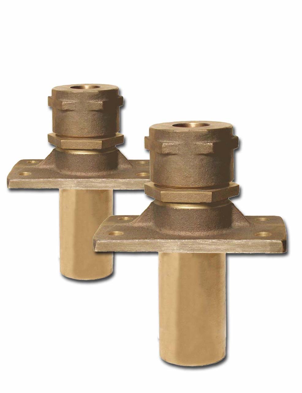
Much more on this later, but replacement part will be a Buck Algonquin part, like those pictured below.
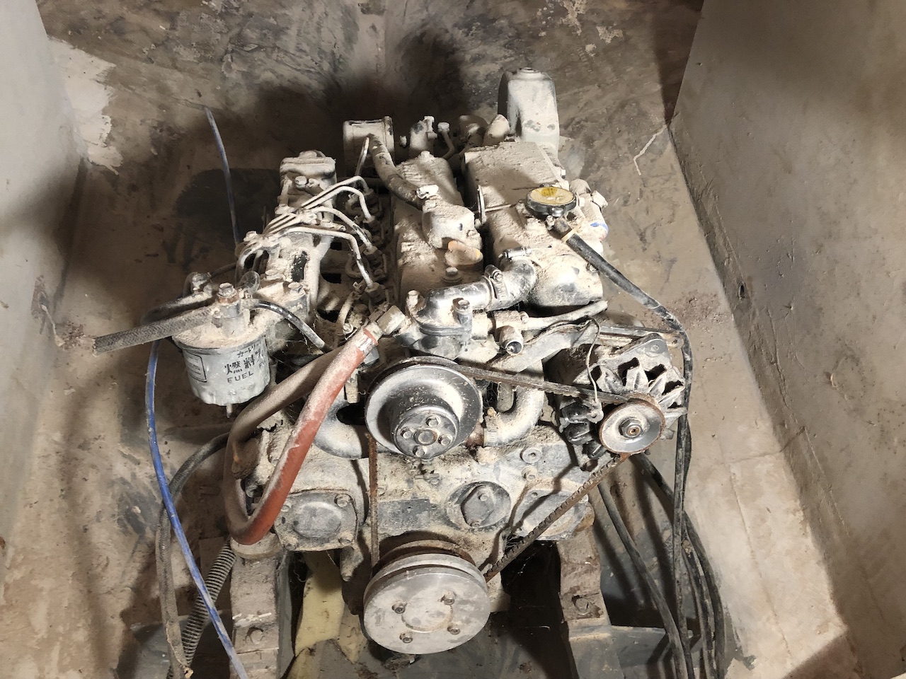
Meanwhile, I cleaned up the engine in preparation for trying to start it up.
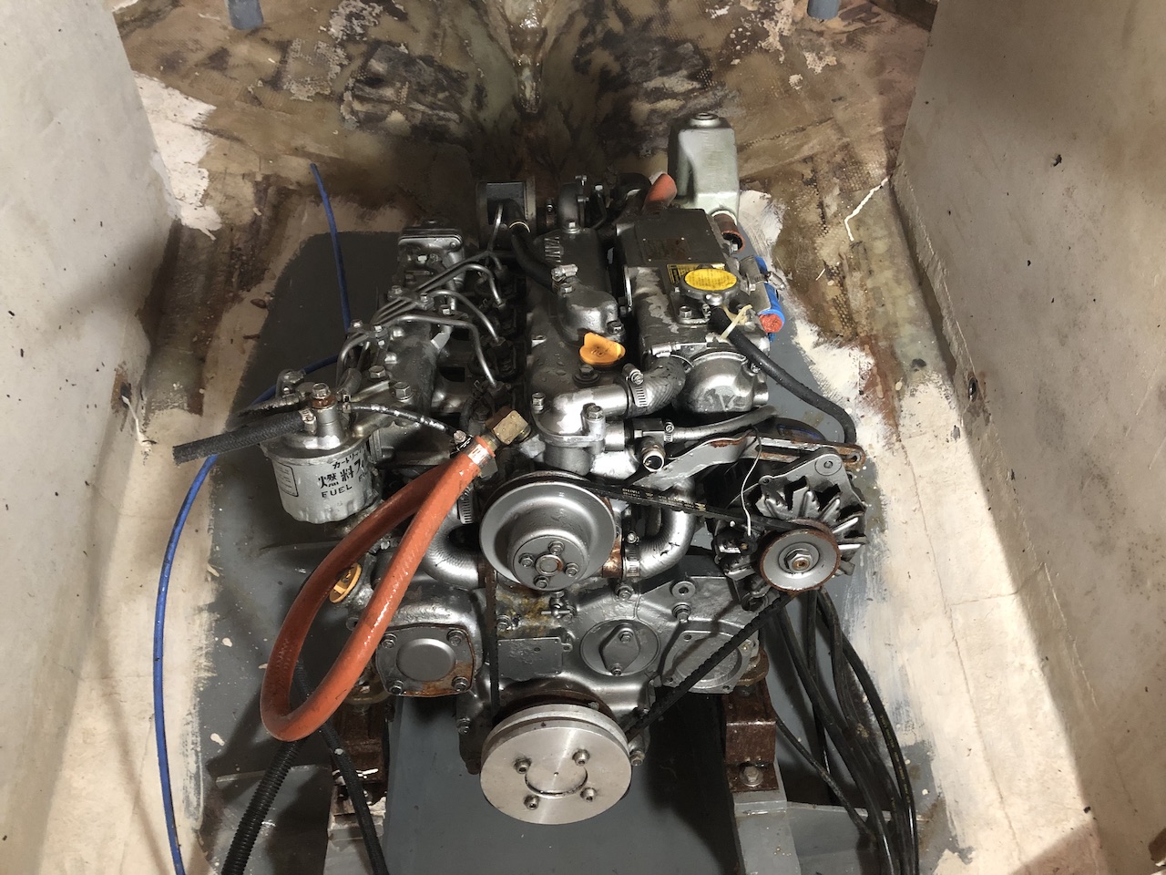
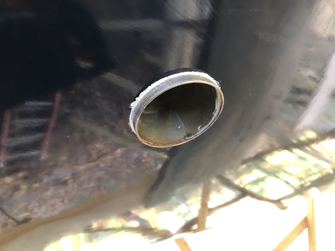
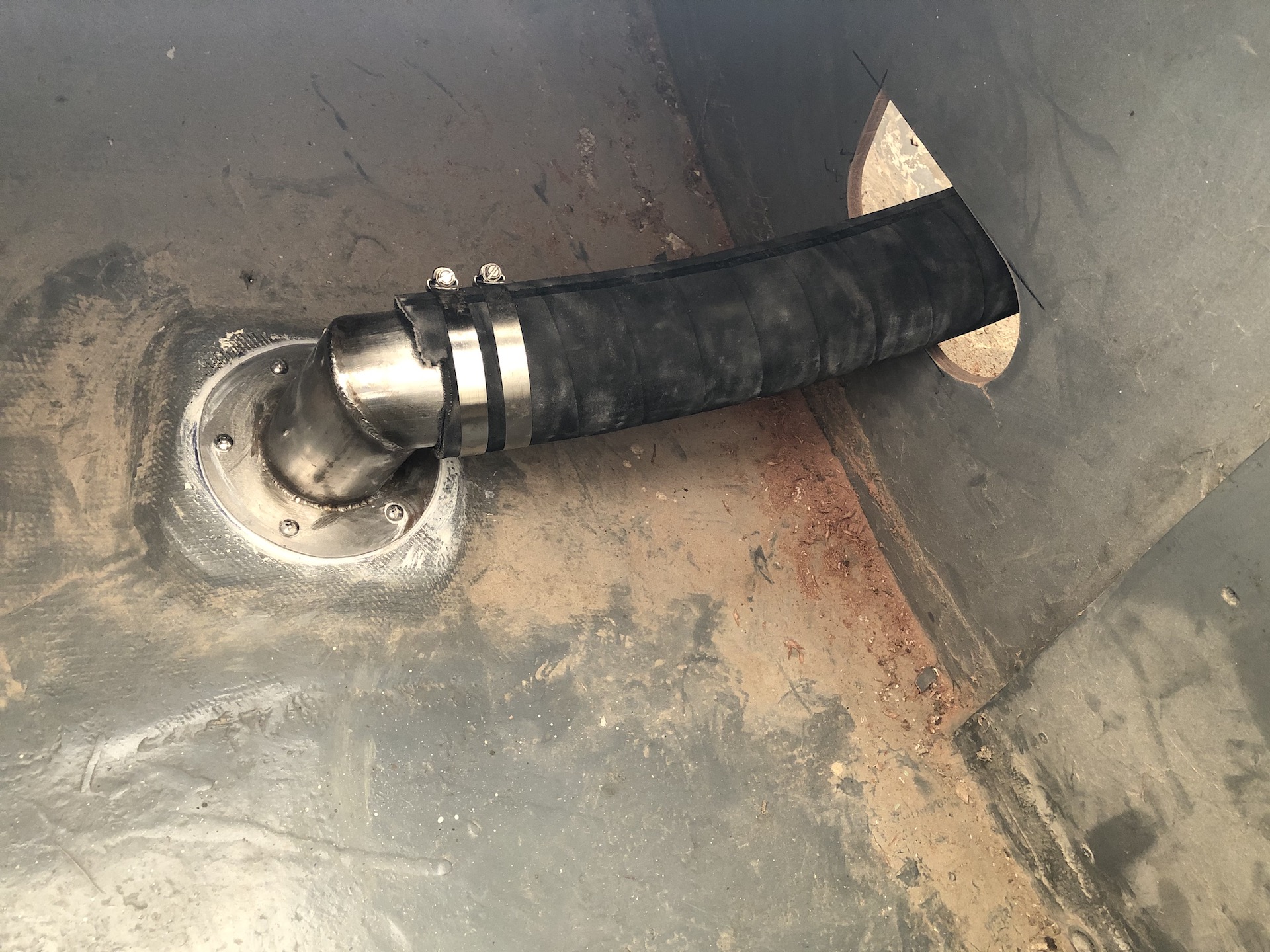
Following the advice of my marine mechanic/electrician, my first task was to get the exhaust system back together. The exhaust fitting on the transom was removed long ago. It will be re-installed in its original location under the aft deck.
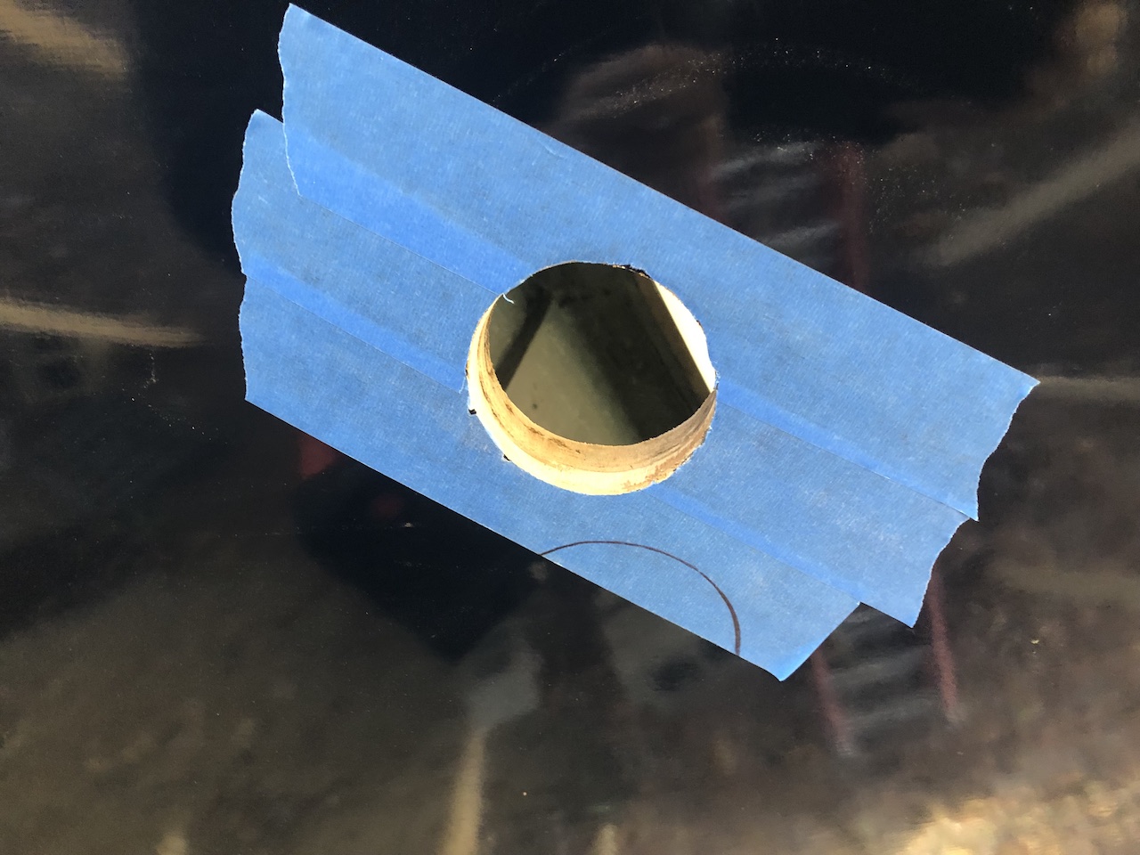
Here is the opening from the outside.
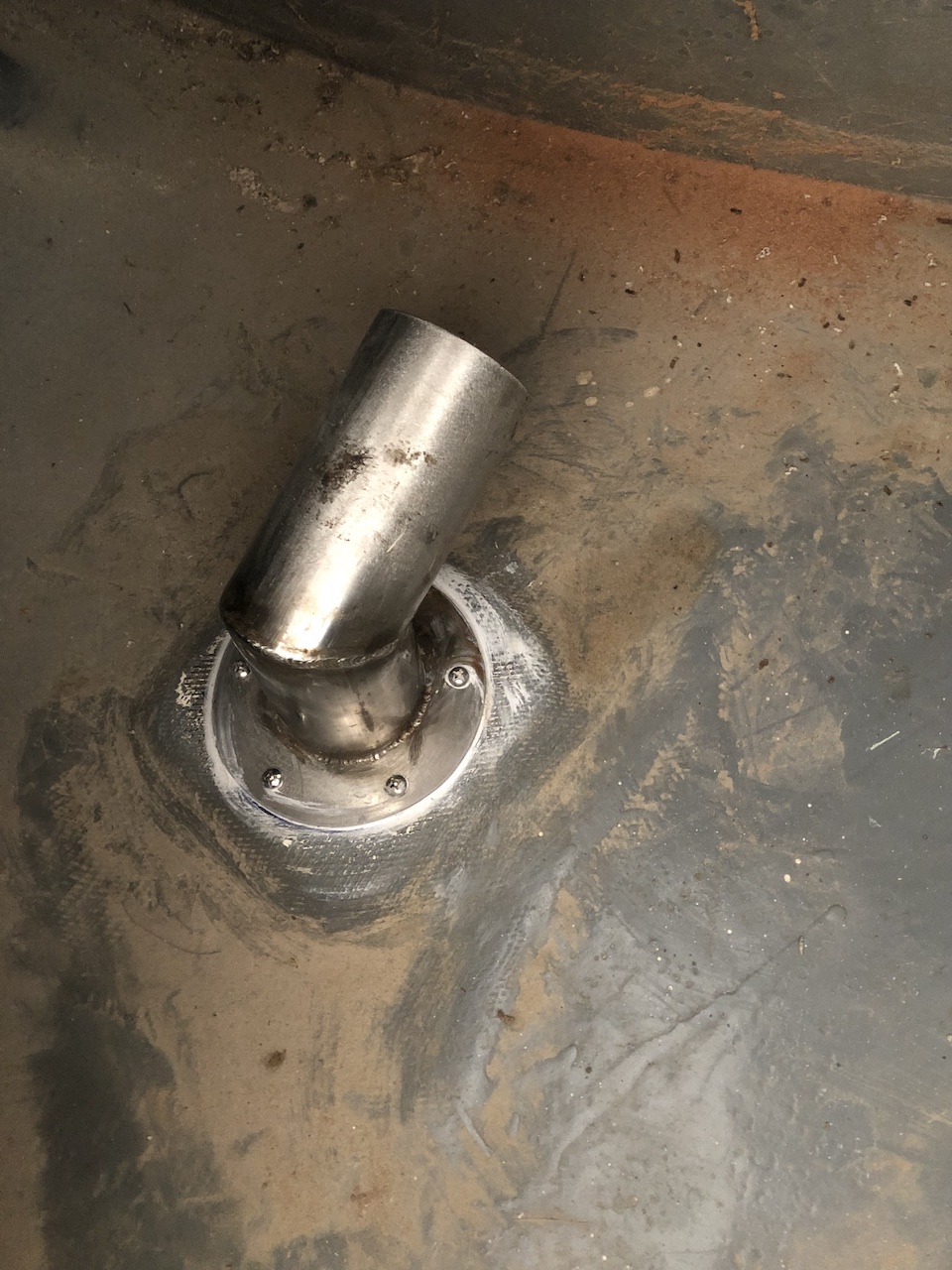
Here it is, bedded in Sikaflex polyurethane sealant.
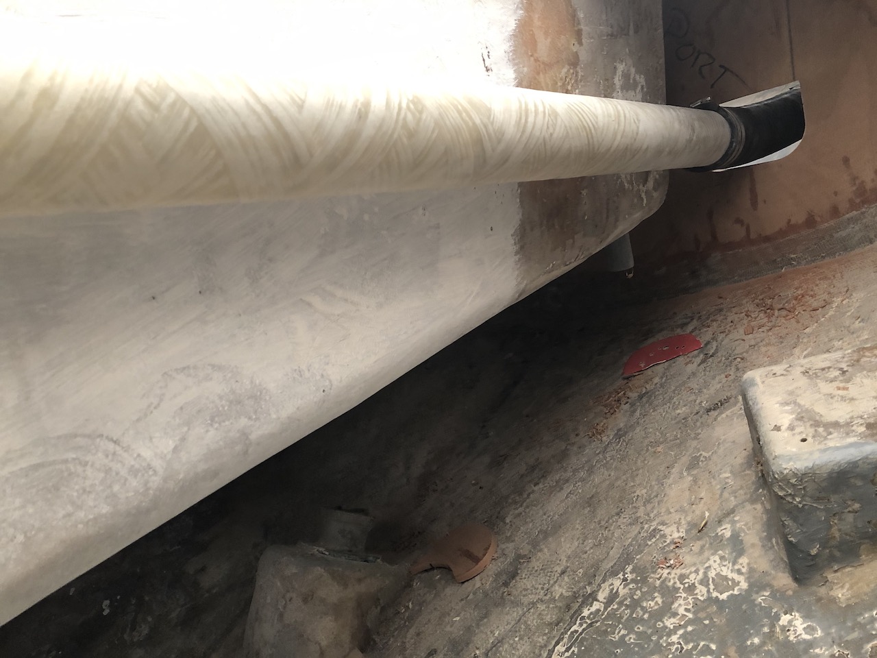
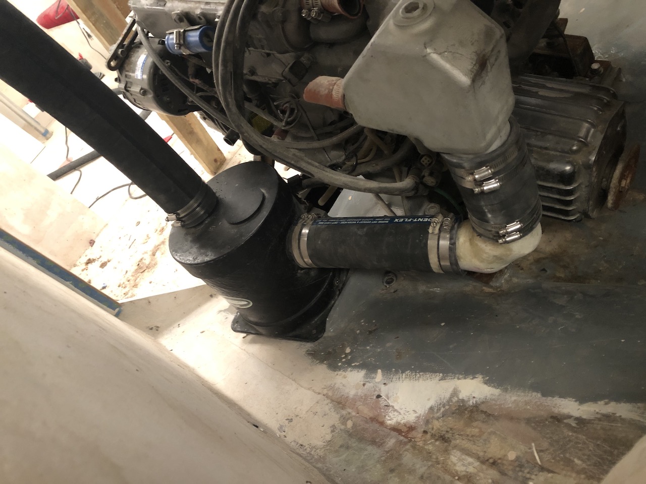
The exhaust exits the engine from a 3-inch OD (outside diameter fitting. From there it meanders through 3-inch fiberglass tube, exhaust hoses, and a lift muffler. (The diagram found 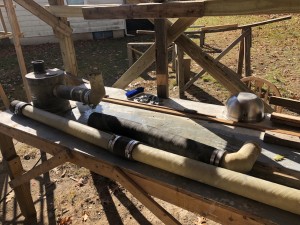
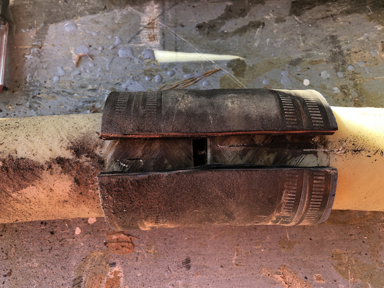
The old hoses had to be removed, of course.
Using a sander, I cleaned everything up.
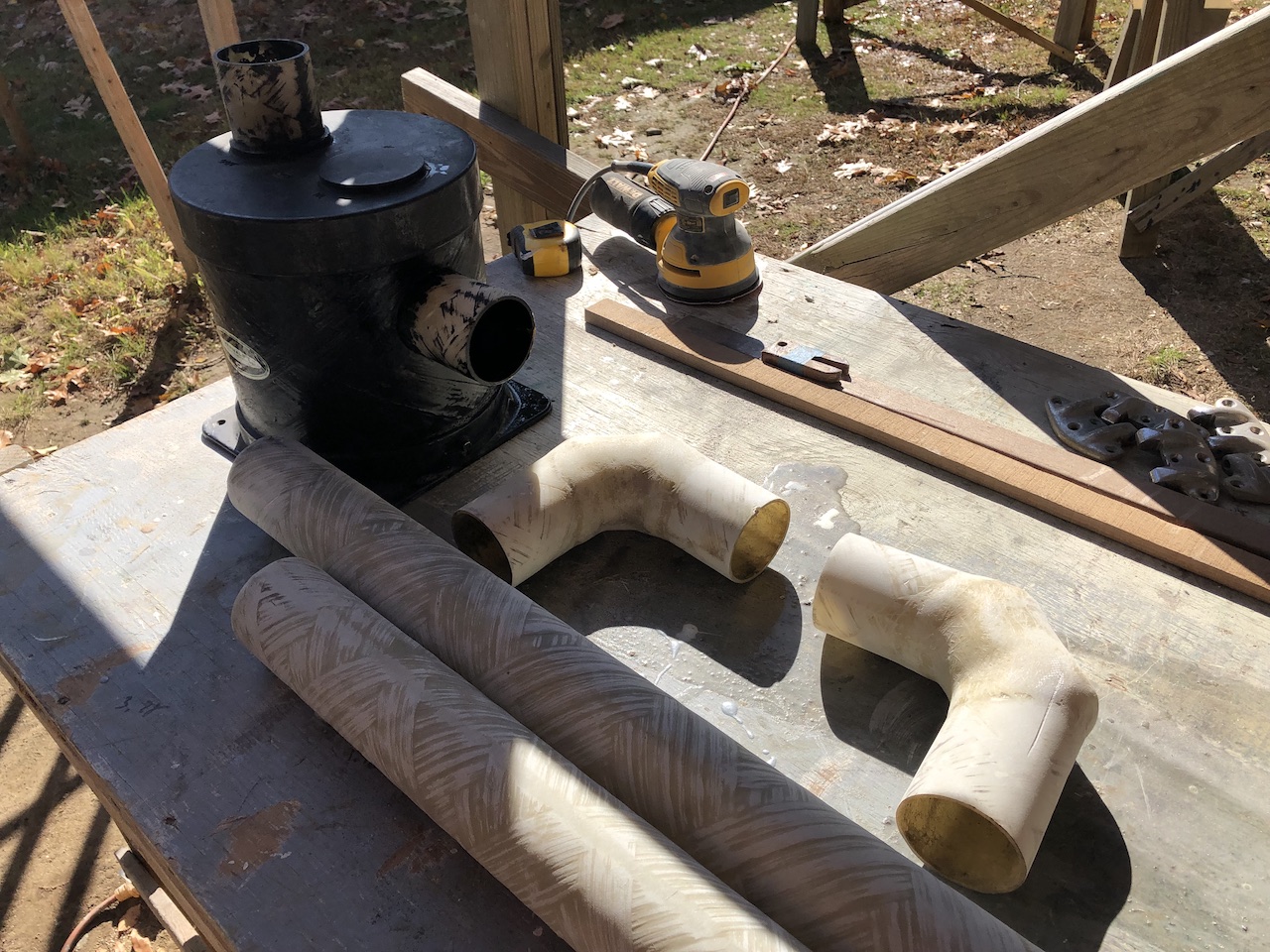
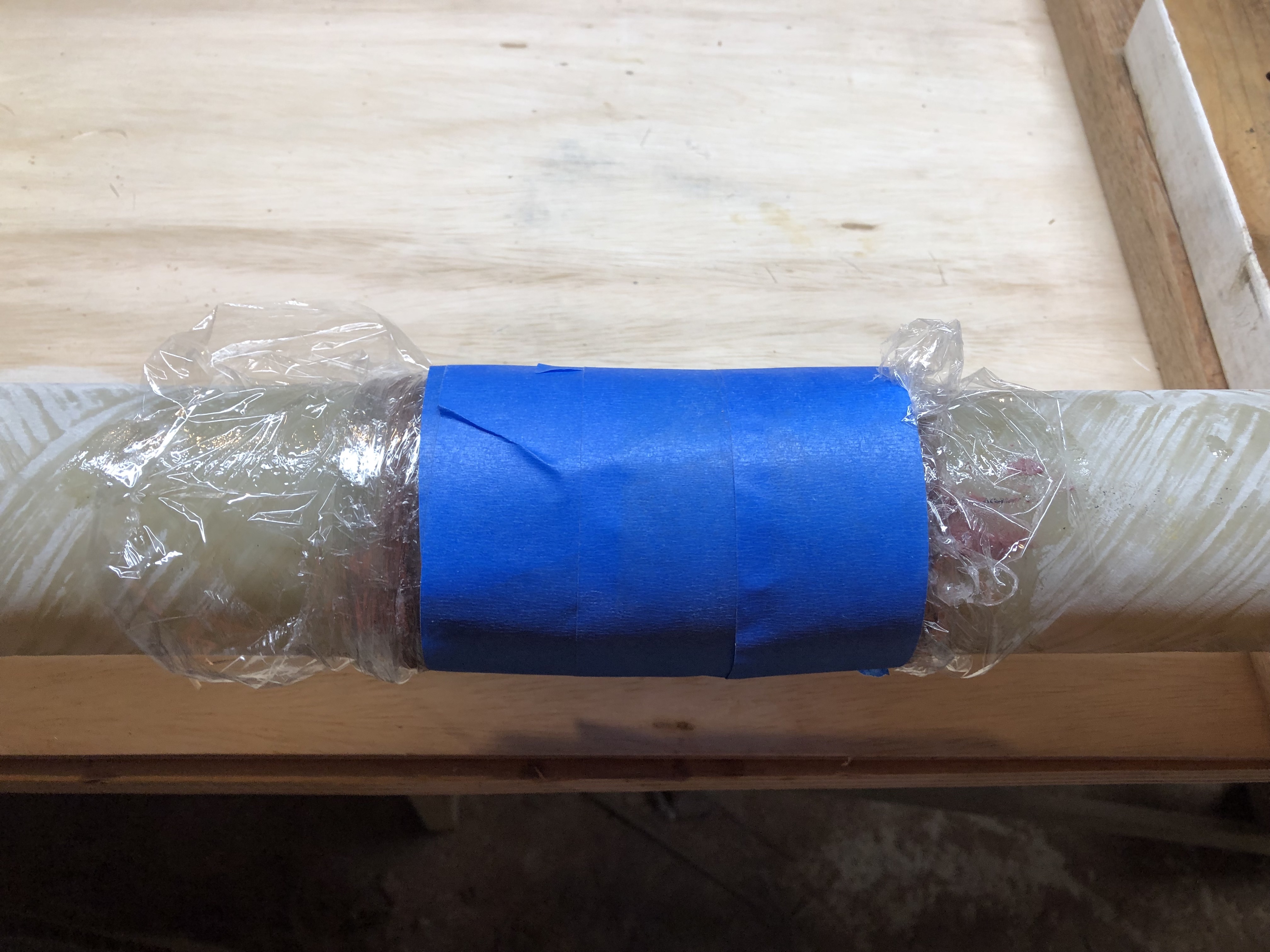
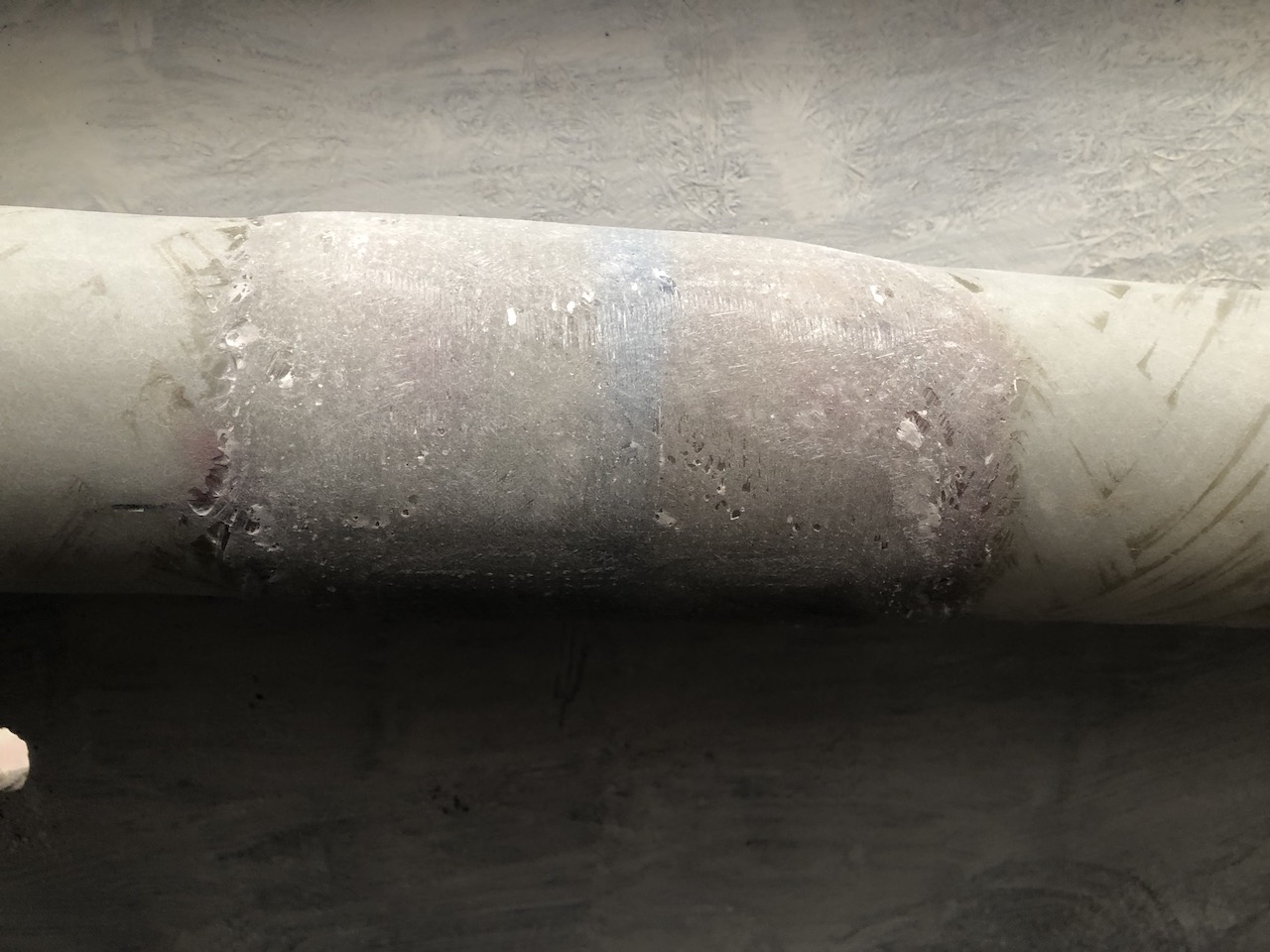
I though that joining the two straight sections of glass tube would be better than splicing them together with hose.
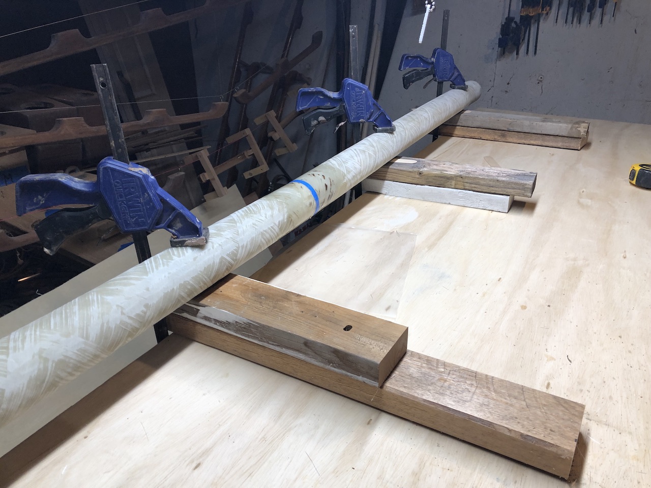
So I glassed them together.
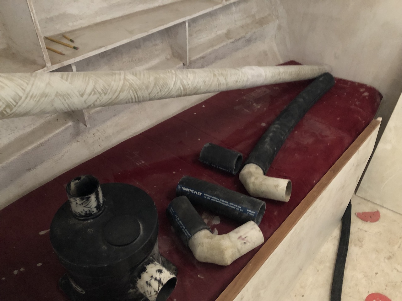
I purchased new hose, which was both expensive and very challenging to cut. Nevertheless, using notes of my measurements, I cut the new hose…
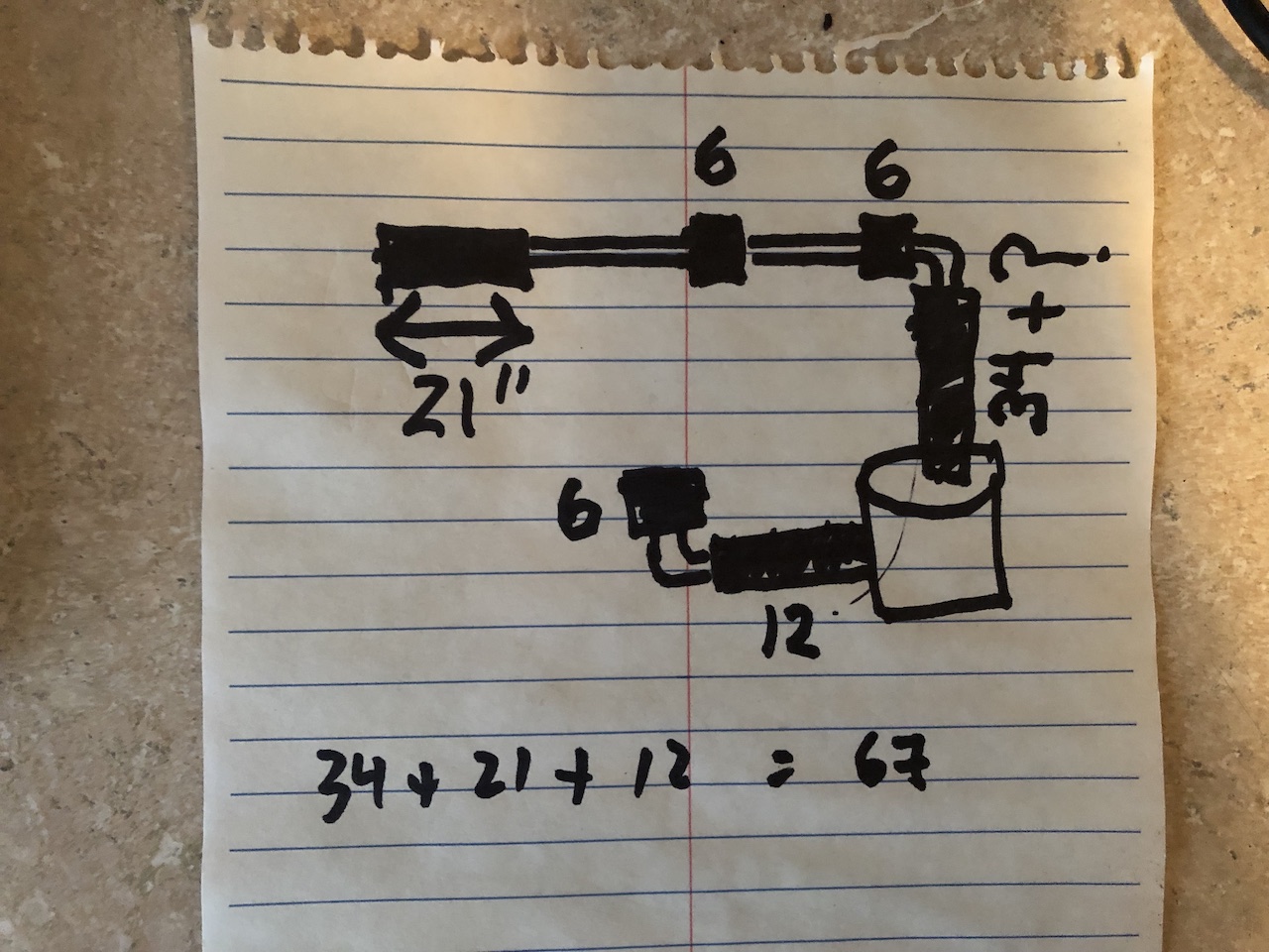
…and laid everything out in preparation for installation.
Here is the transom fitting.
Here we are looking aft from under the cockpit.
The join of the two tubes.
Looking forward from under the cockpit.
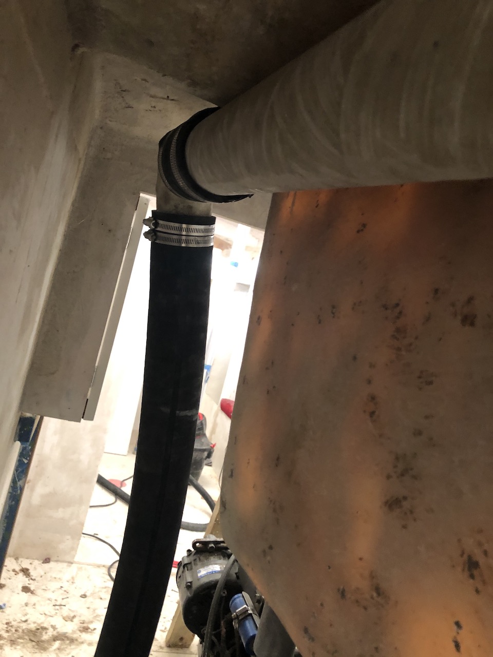
Looking down and toward from under the cockpit.
Trish Martin
11/11/2019 — 2:03 am
Awesome, Mike!!!