1/23/21: Panel frames, Salon furnishings, Lifeline system
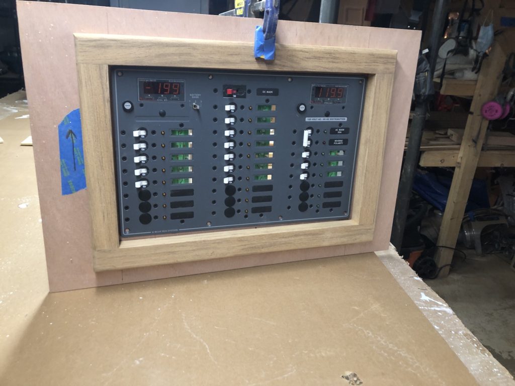
The original electric panel, shown below, was mounted on a swinging door that opened to the engine compartment. It was mounted on the “step” on which the upper section of the companionway ladder stood.
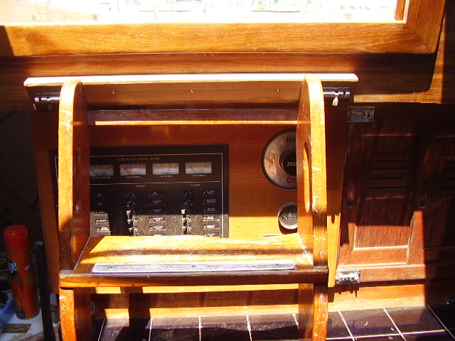
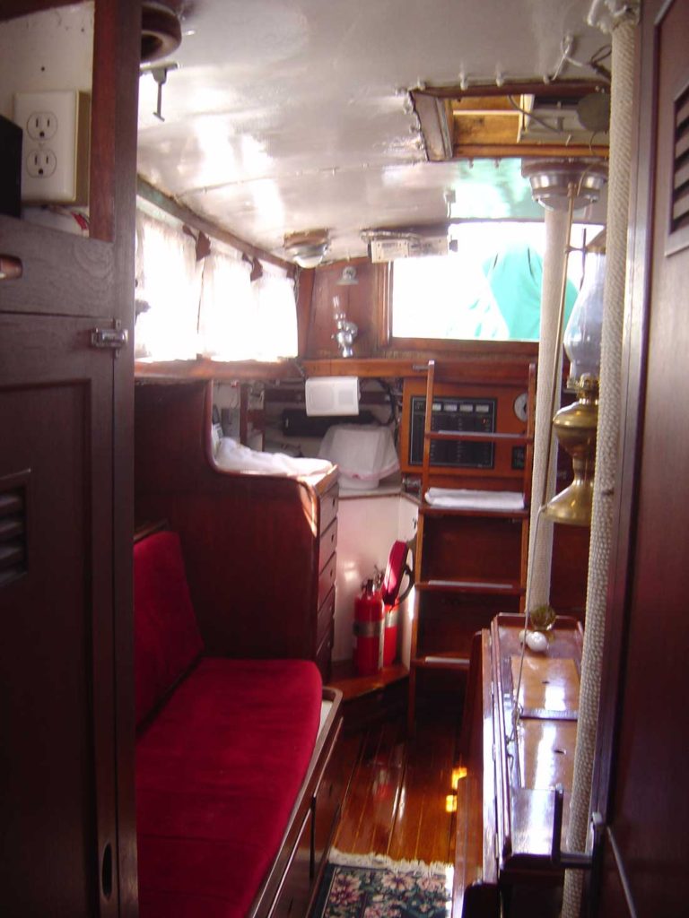
It was set back, under the bridge deck, and the companionway ladder protected it from being kicked. Here’s another look from a photo taken by the previous owner sometime before 2007. Note the original table in the salon.
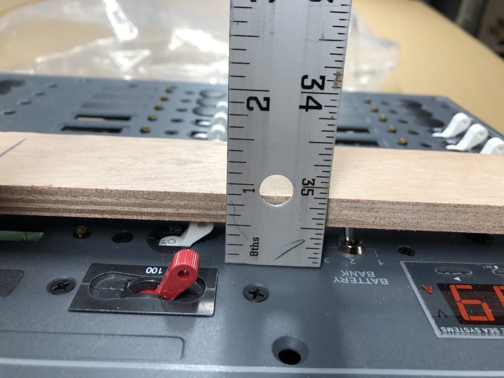
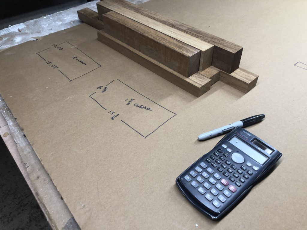
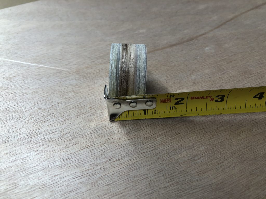
The new panel will be mounted (as discussed in the last post) on a bulkhead, and will susceptible to falling bodies and spilled drinks. It must be protected. In the below photo I am determining how far switches protrude above the surface of the panel (1/2 inch).
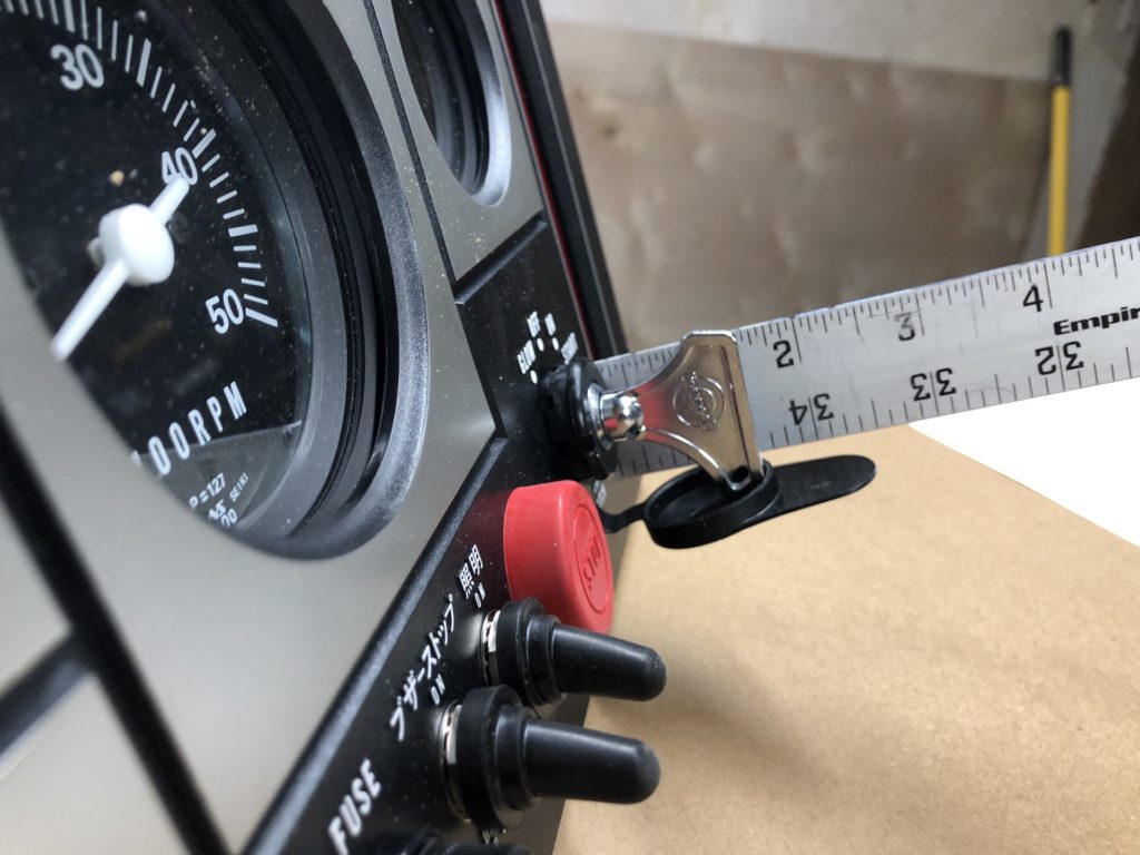
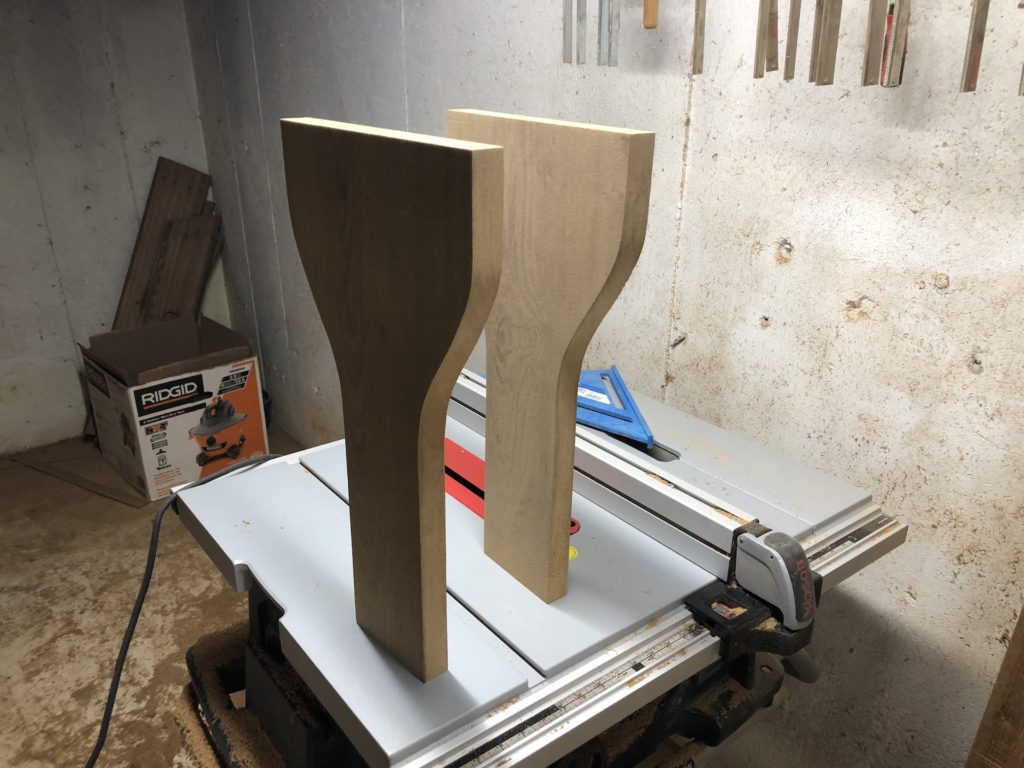
While I was at it, I did the same for the engine control panel (1.5 inch).
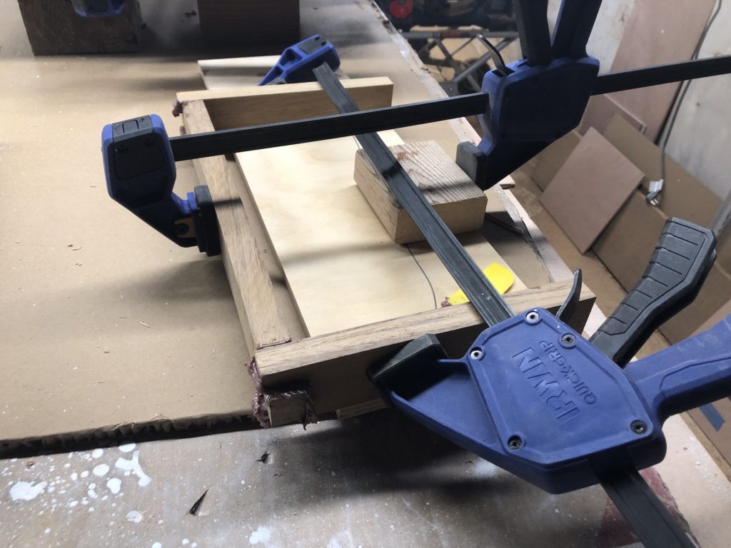
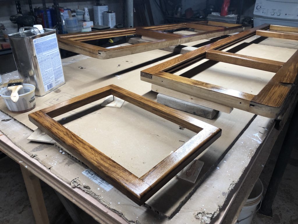
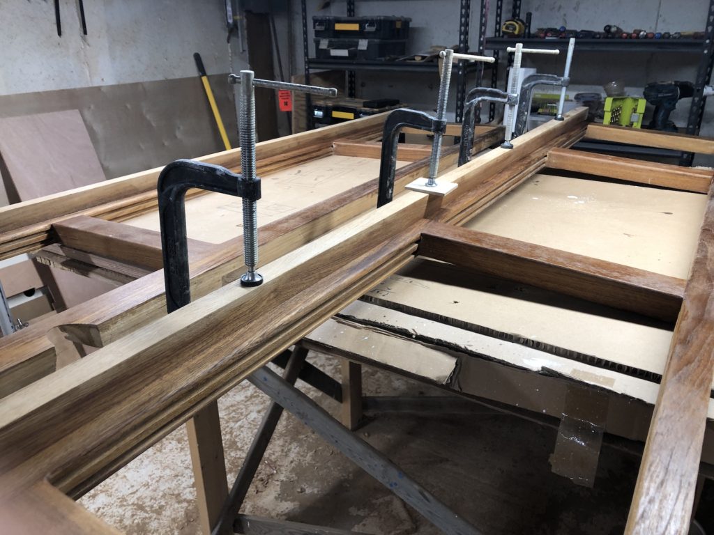
Next I built frames for each panel.
Skipping details like you’ve seen before, here is the glued-up frame for the engine-control panel. It is open on the bottom, as was the original. This will be mounted in the cockpit.
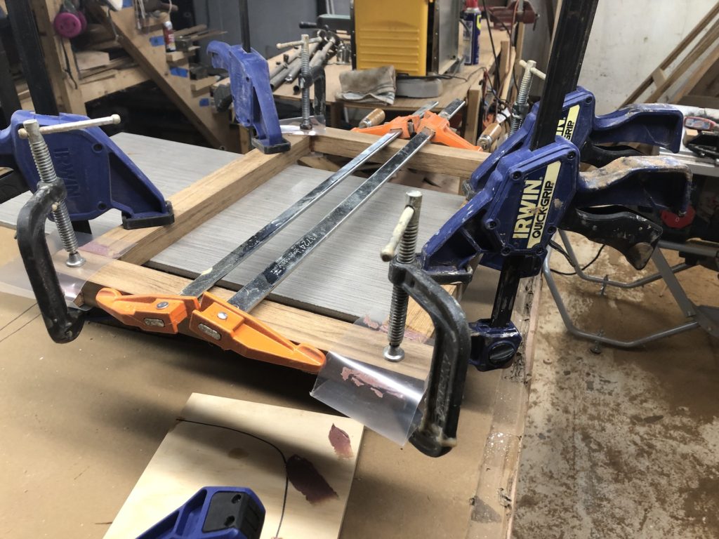
Here is the glued-up frame for the electrical panel.
Fast forward…

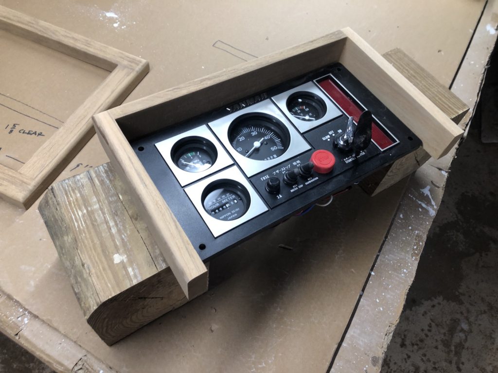
The frame for the electrical panel will remain unvarnished. The bare teak will blend well with the bare teak on the cockpit seats and cockpit gratings.
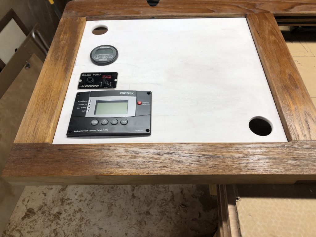
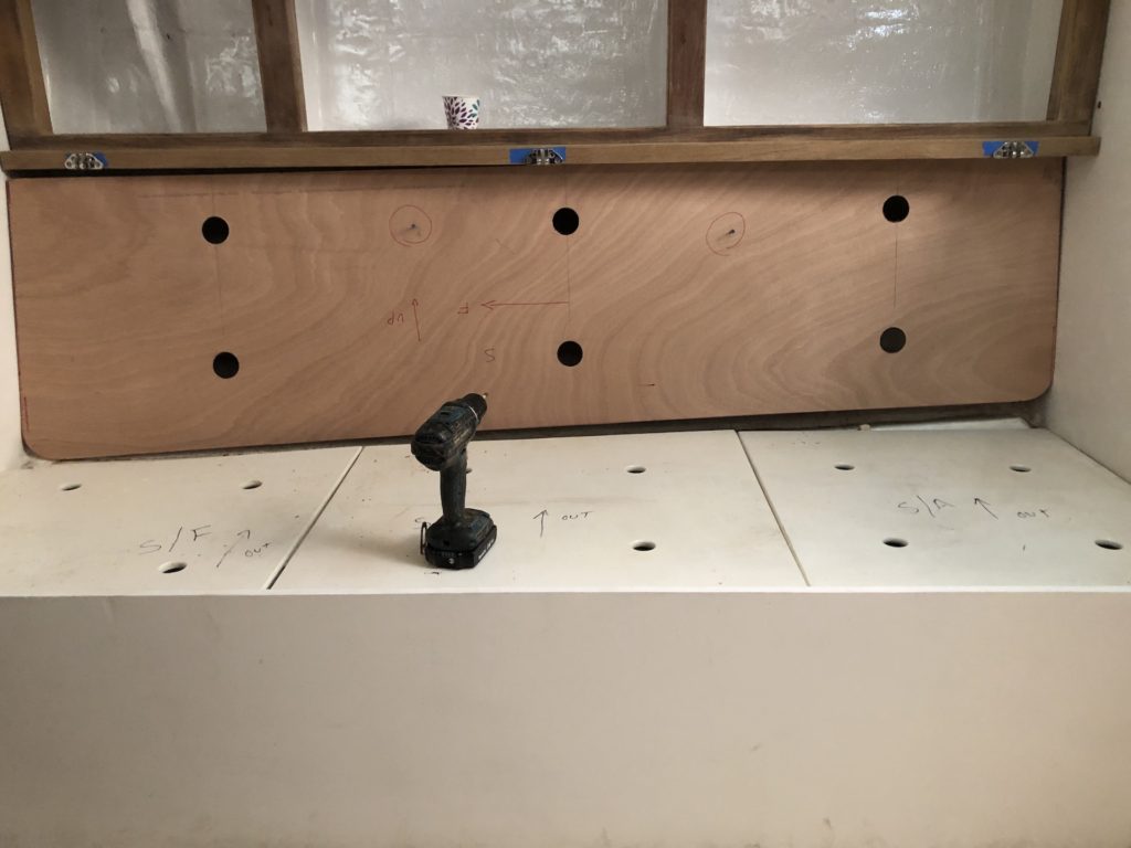
My electrical guy suggested cutting more holes in the bulkhead for additional equipment, like a bilge-pump switch, inverter controls, and a battery monitor. I suggested, instead, to repurpose the starboard-side forward cabinetry compartment for these items. He agreed, and I made a new drop-in panel.
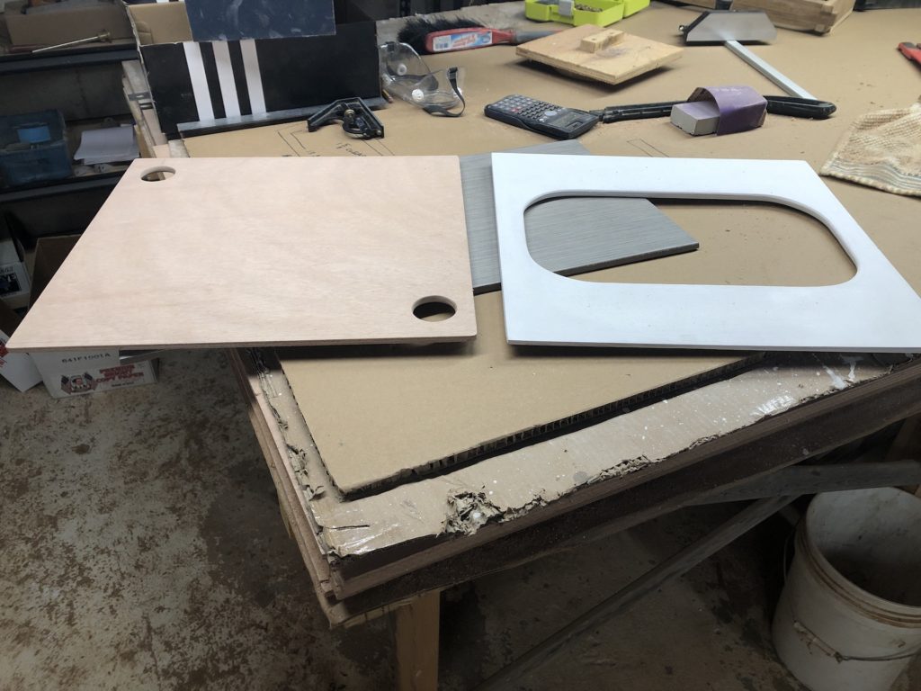
Here I’m marking the cutouts…
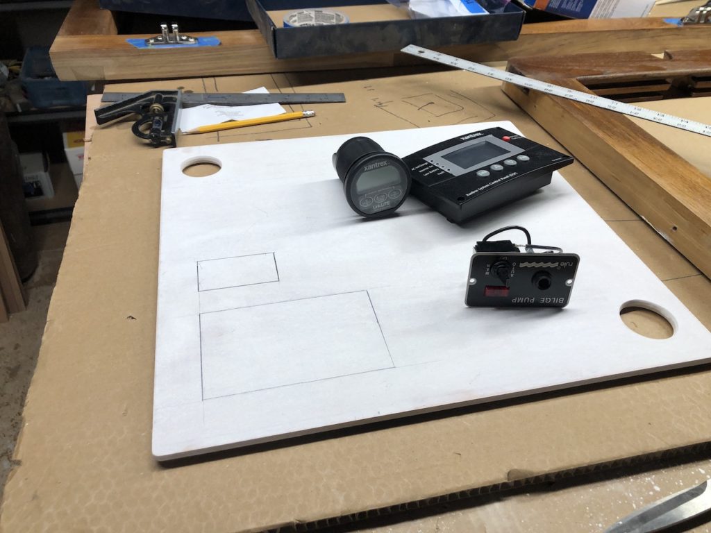
…and then test fitting. Top to bottom: battery monitor, bilge-pump switch, inverter control.
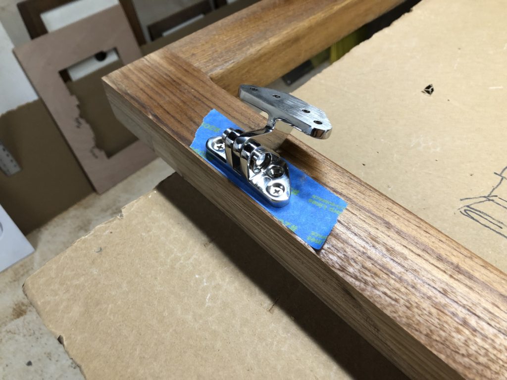
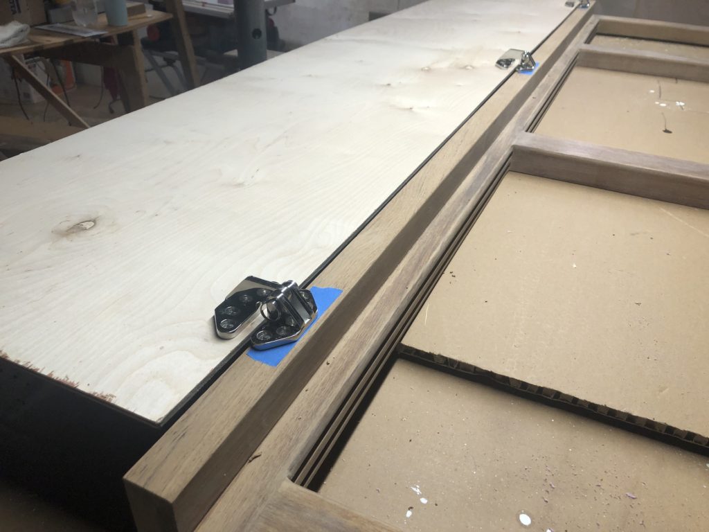
Backrests are needed in the salon. These hatch hinges are ideal because they provide some offset for the cushion, and the two sides can be separated by removing a clevis pin.
I made mock-ups out of cheap ply, but found that when folded up they leave too little room for a decent backrest cushion.
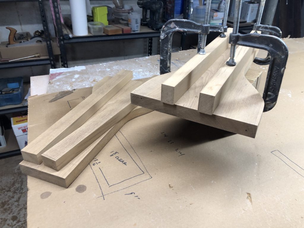
I reverted to the original design, which called for a strip of teak to set the hinges away from the frame. In this case 1.5 inches.
Now when the backrests are folded up there is room for a 3.5-4 inch cushion, which should be plenty. I’ll soon be consulting with fabric people about cushions.
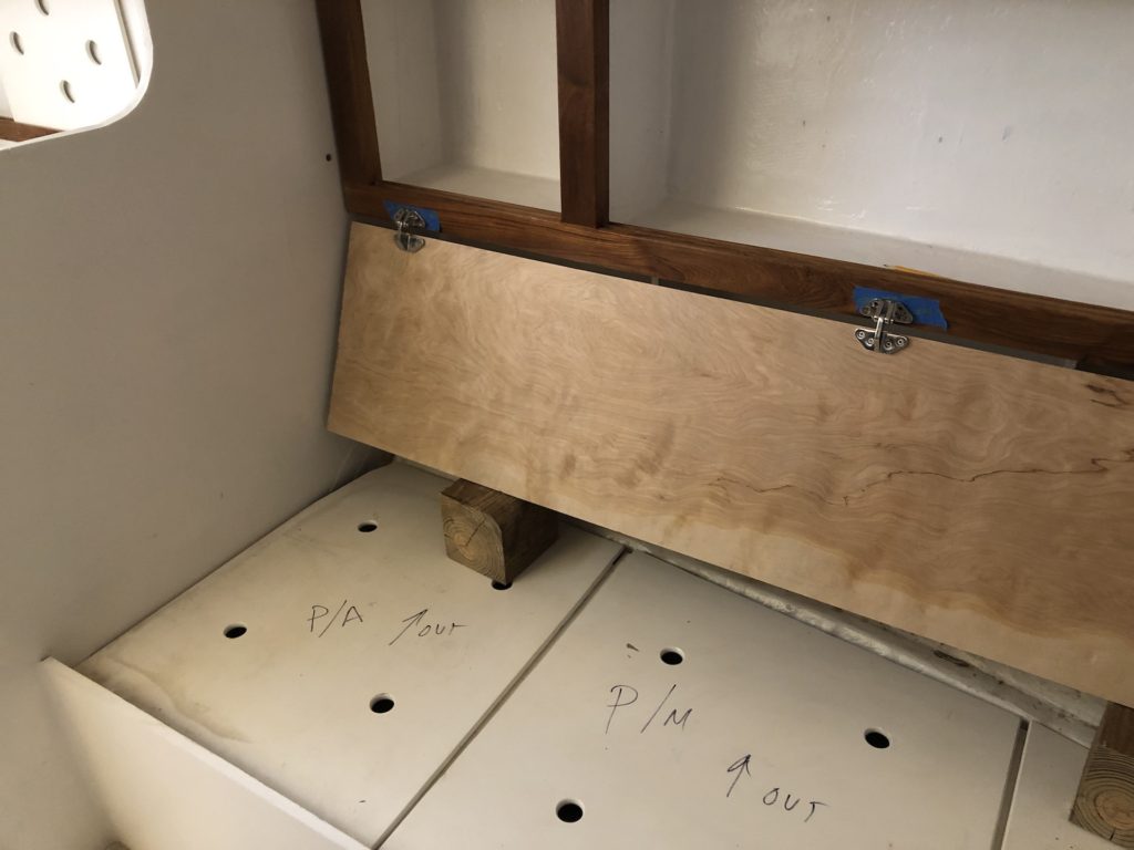
The space behind the backrests (below the frame in the photo below) is somewhat unsightly, but usually hidden by the backrest. Nevertheless, when the backrest is folded up to make a bunk, it would be nice to have a better view.
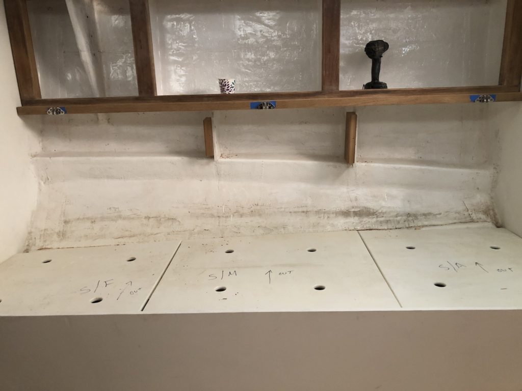
In the photo above, note the two teak blocks I’ve screwed to the shelf supports under the frame. I made a covering board from thin plywood and it will be screwed to the two teak blocks. In the photo below it is NOT screwed to the blocks because adjustments are needed.
More on backrests and covering boards next time.
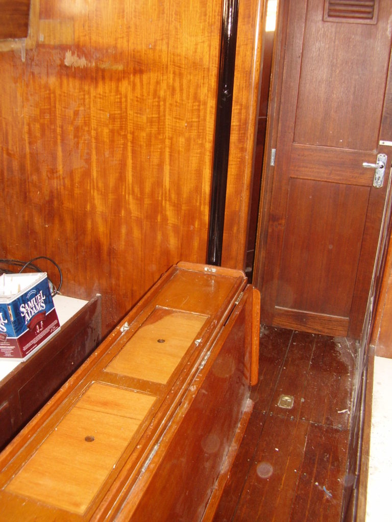
Below is the original salon table. It could become gimbaled (meaning it could be set to swing with the rocking of the boat) by adjusting a few latches, and there were very heavy lead weights that would enforce the gimbaling motion. Removing the table to improve access to the under-sole area was a big project, that I expect nobody ever did until 2007 when I did a minor refit. I have no interest in a table like that again.
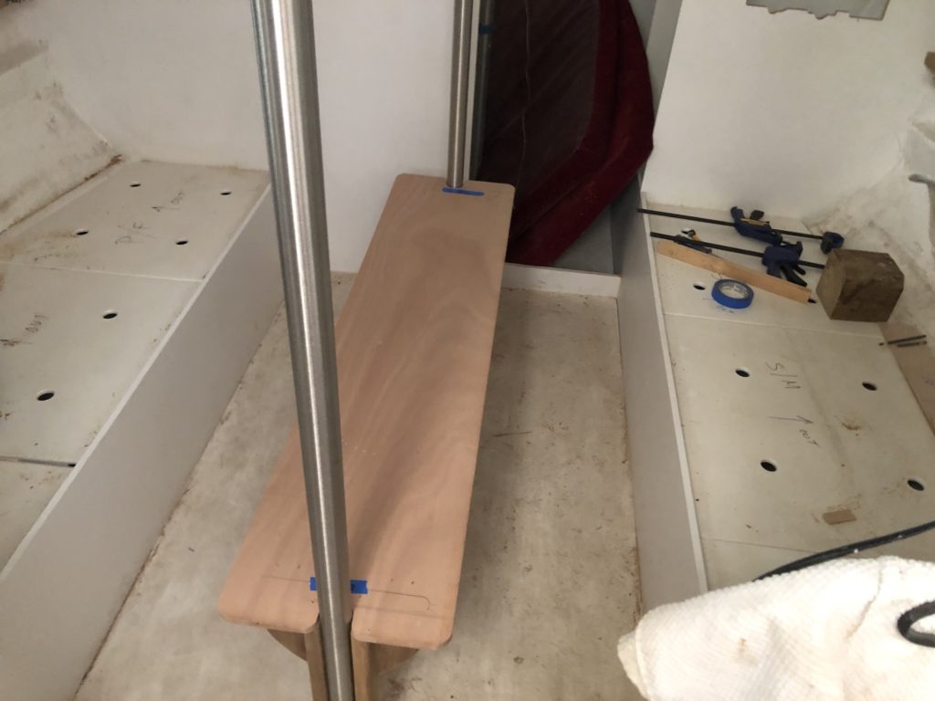
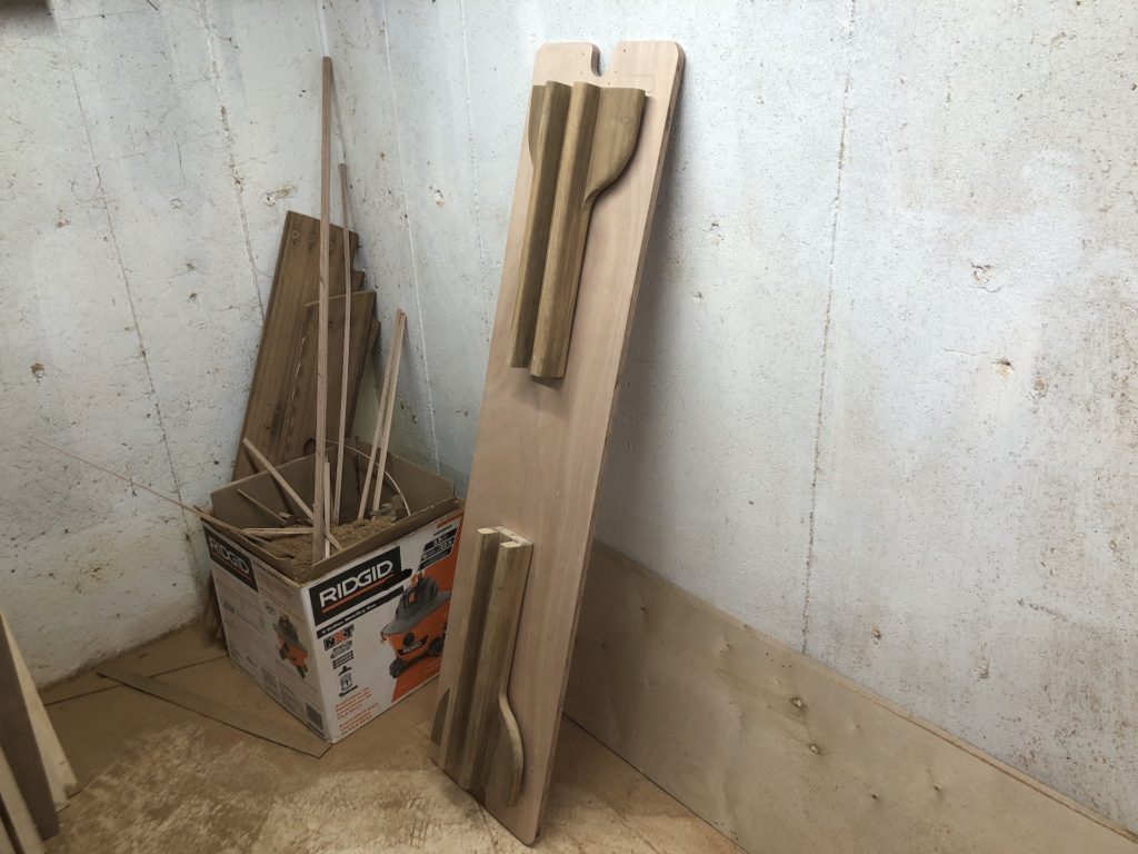
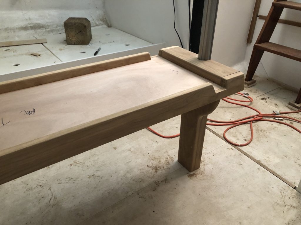
That said, I need a table, and I’ve brainstormed for many years. Finally I came up with a design for a table that would (1) utilize the compression posts to stabilize the table (2) be light and easily removable, and (3) be adjustable in height and width so that it can easily be transformed from “coffee table” mode to “dining table” mode. So far I’m only working on the “coffee table” mode, and adaptability to “dining table” mode might come after the boat is in the water. The following pictures show the beginnings of the process.
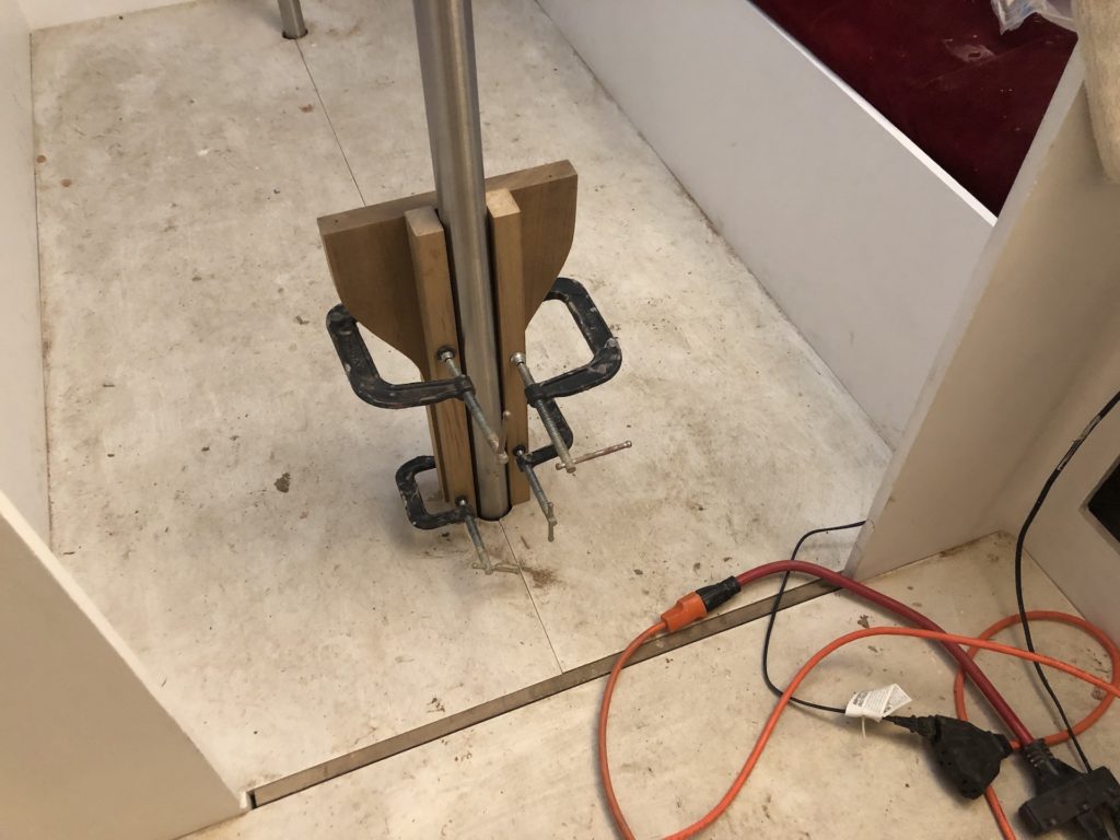
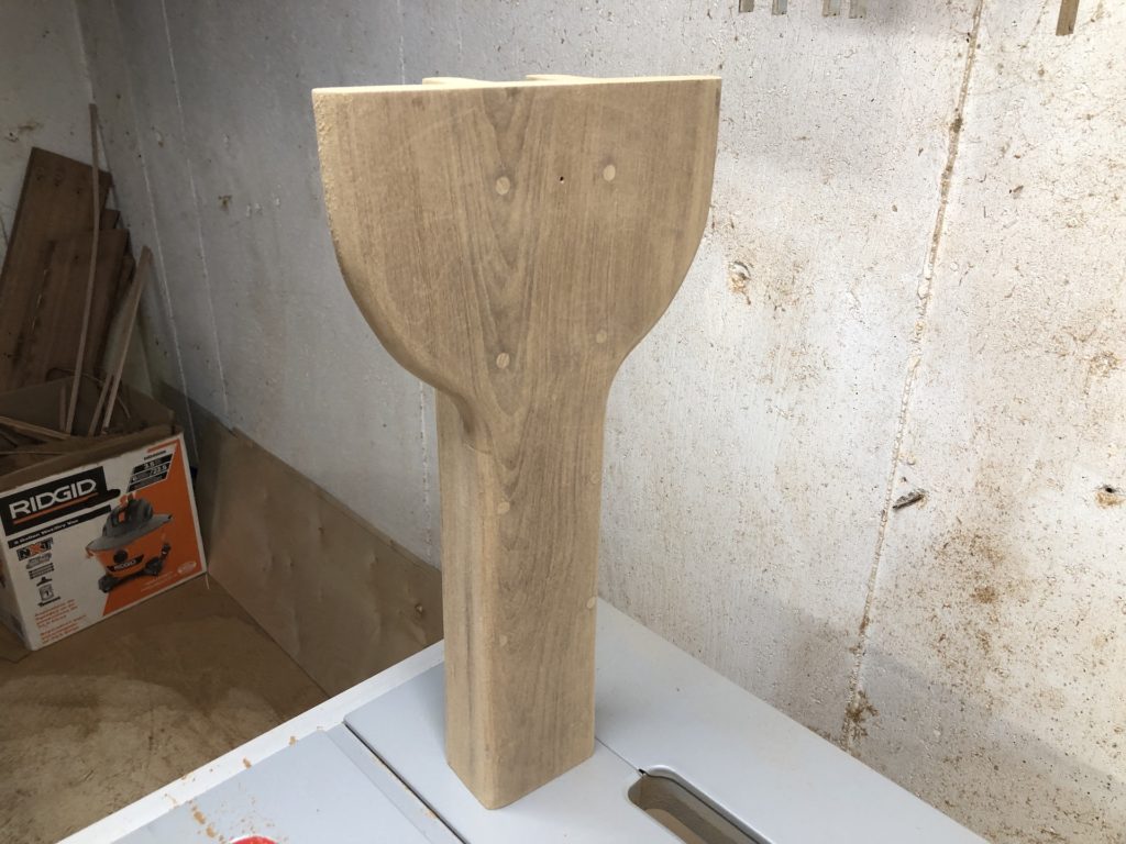
The table is 5/8 inch plywood, and the two legs are built to each straddle a compression post. The legs are hinges to they can be easily folded up and the table removed.
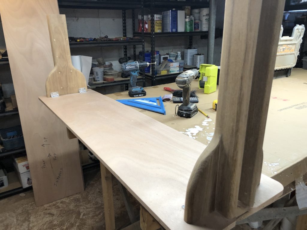
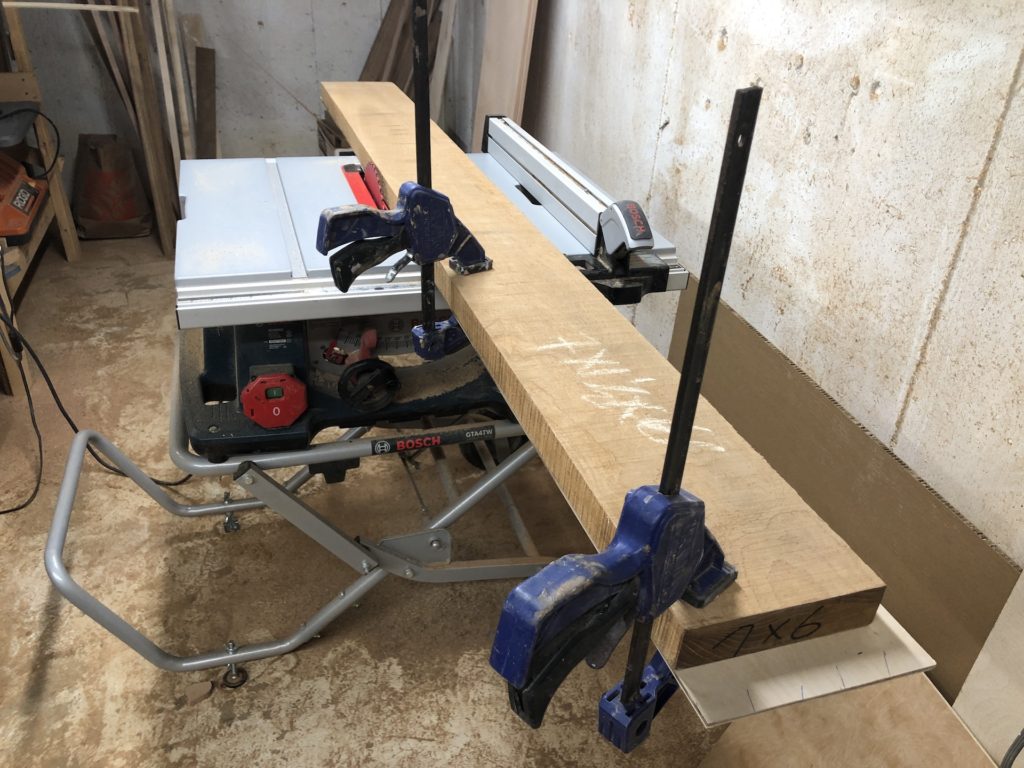
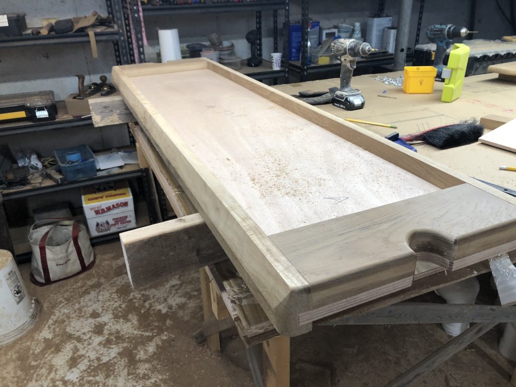
There is a lot more to do, including teak fiddles/trim, paint, etc. I continued by straightening a teak board in the usual way:
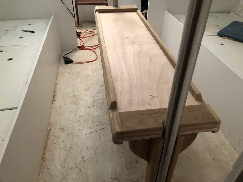
The so-called “fiddles” both stiffen the table and serve as a guardrail for items placed on the table.
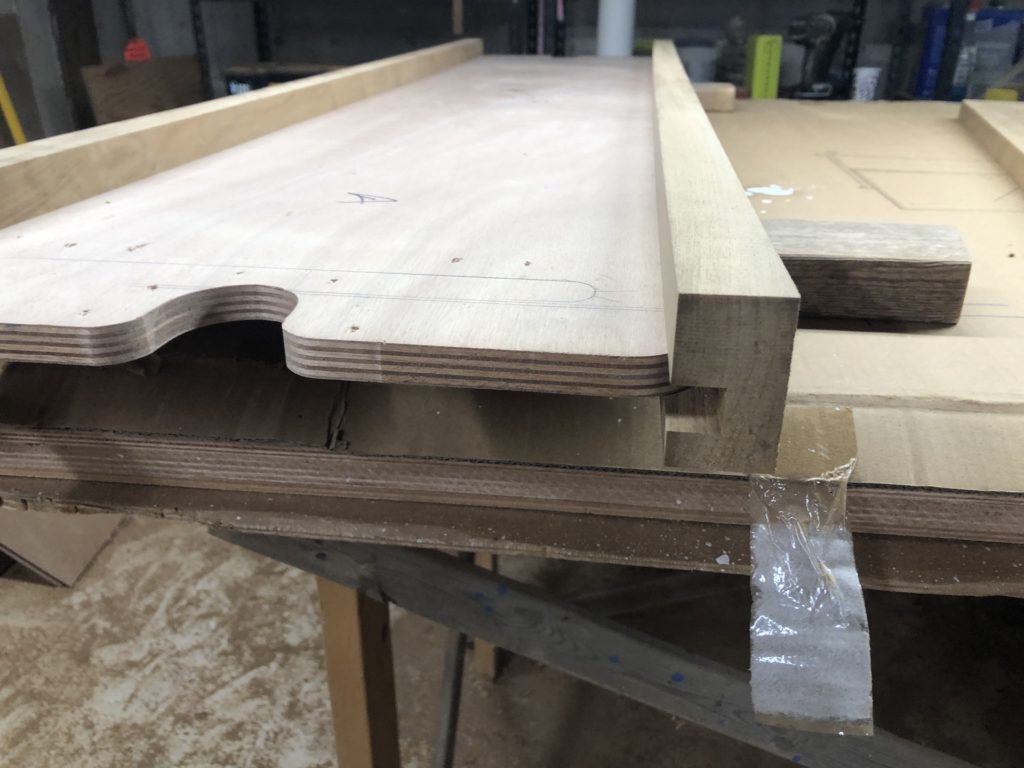
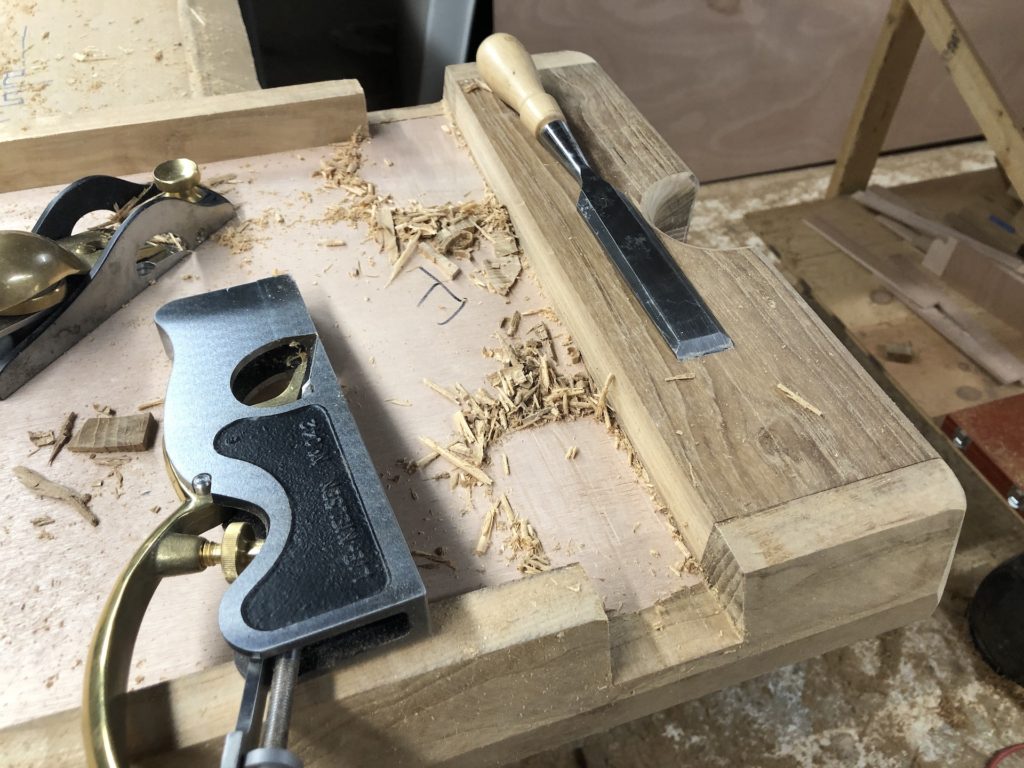
I filled space at the ends with solid teak. The hinge screws deserve more than 5/8 inches of plywood to hold them. Fiddles should be beveled, but only on the outside:
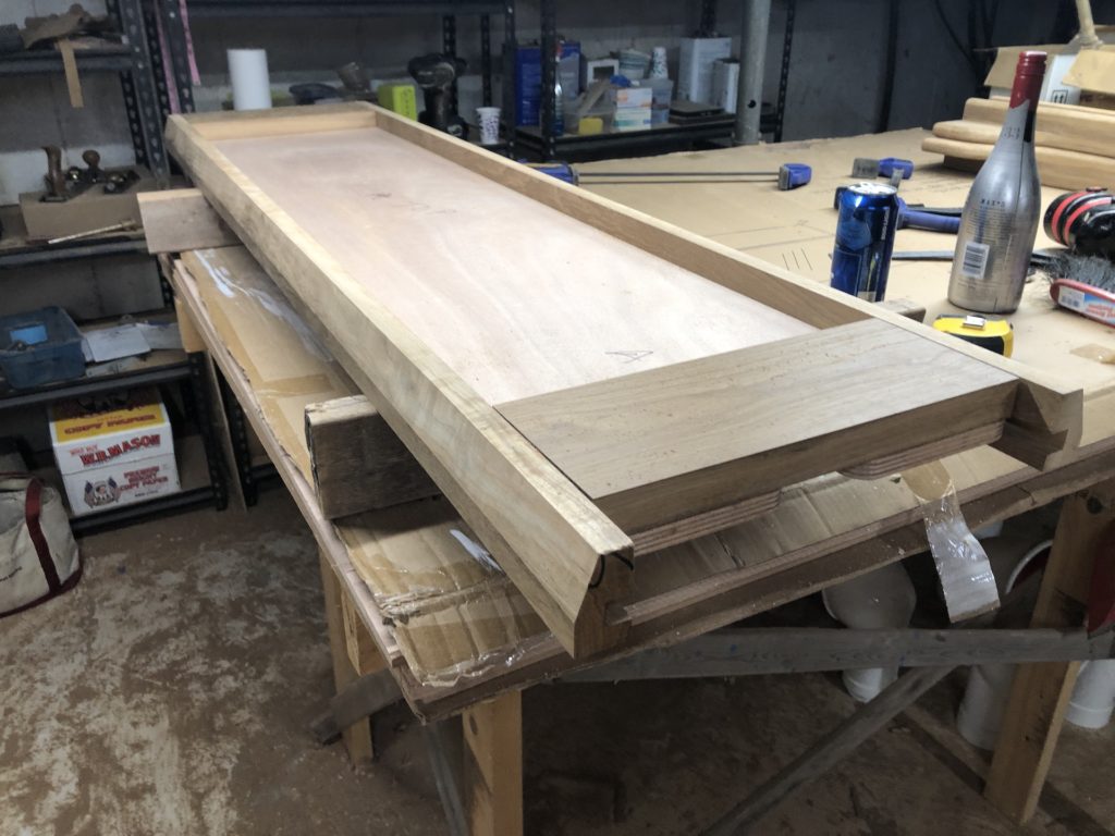
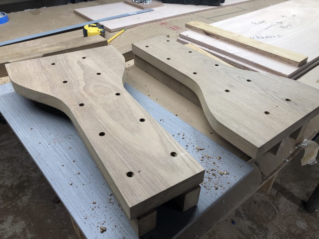
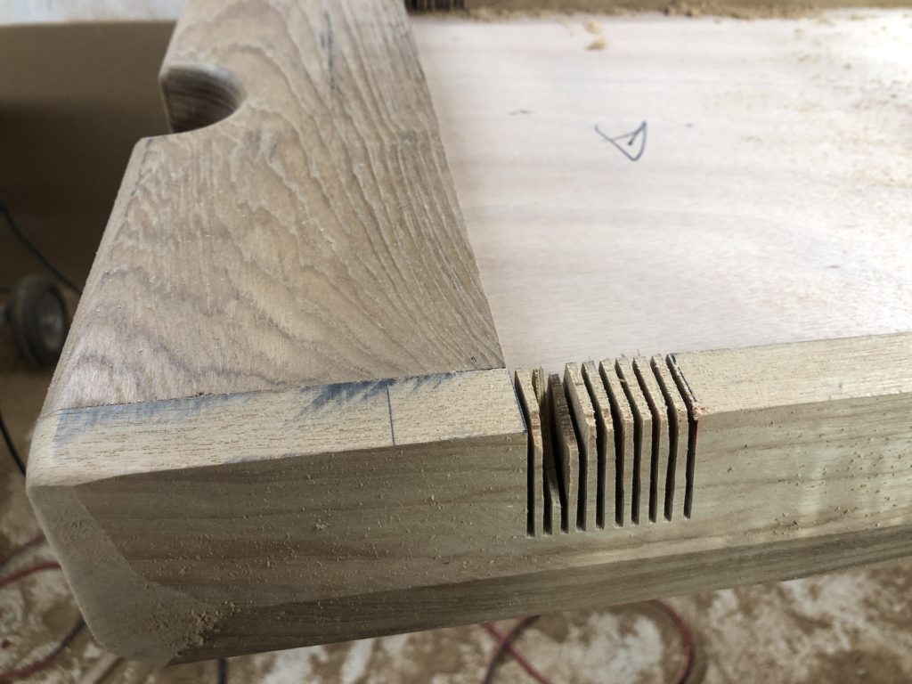
Trimming the ends and shaping the cutout for the poles:
Tables should be easy to wipe down, so there should be no sharp corners where crumbs can accumulate:
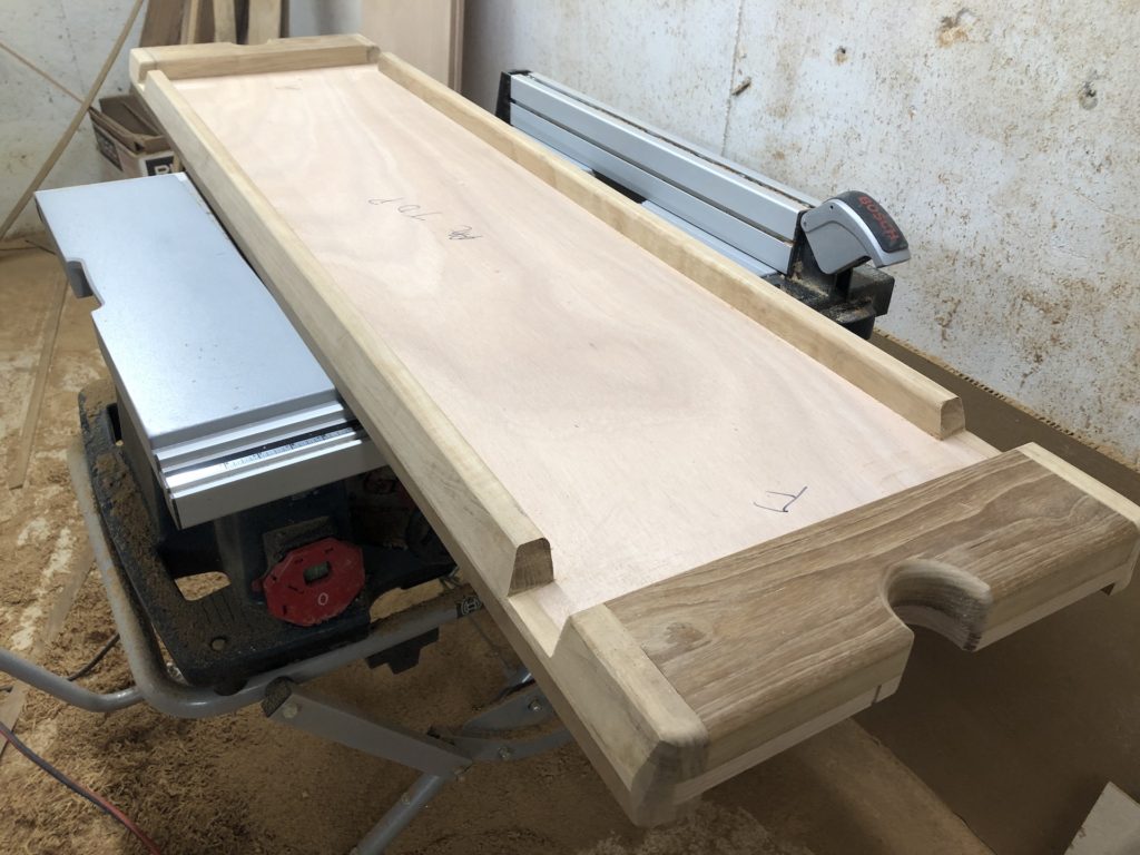
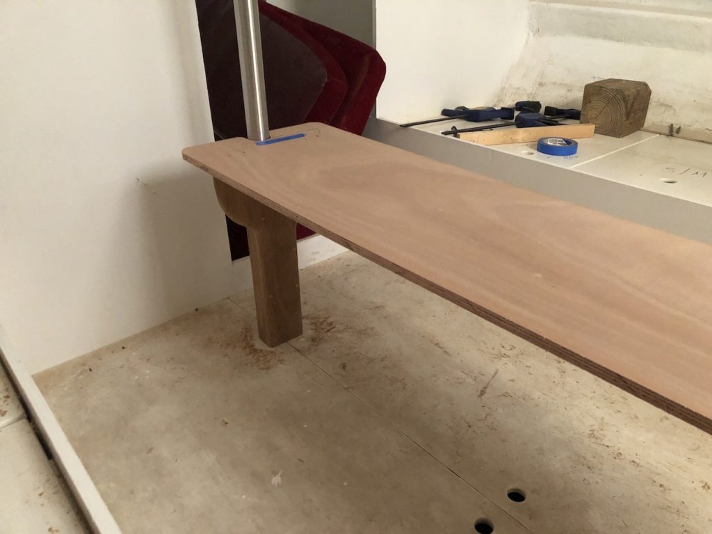
After more sanding and shaping, I reattached the legs for a test fit.
Next I will disassemble everything and prepare the plywood part for primer.
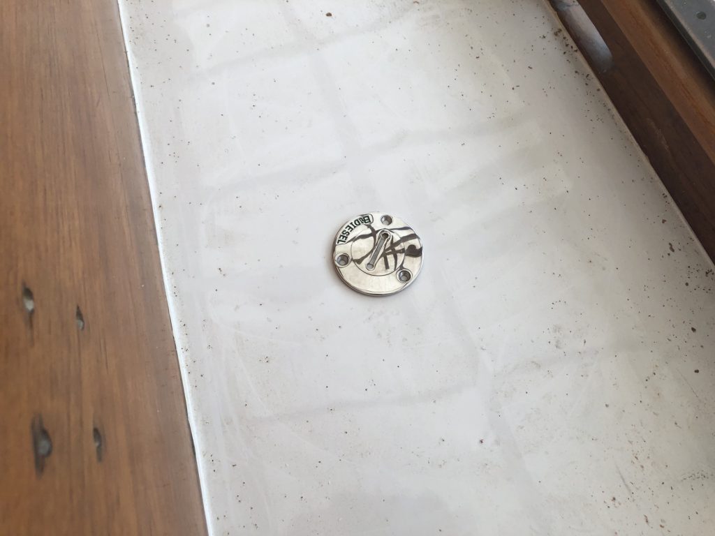
Now for some odds and ends. I will need three “deck fills”. One for holding tank pump-out, one for water fill, and one for fuel fill. I cut the hole for the diesel fill.
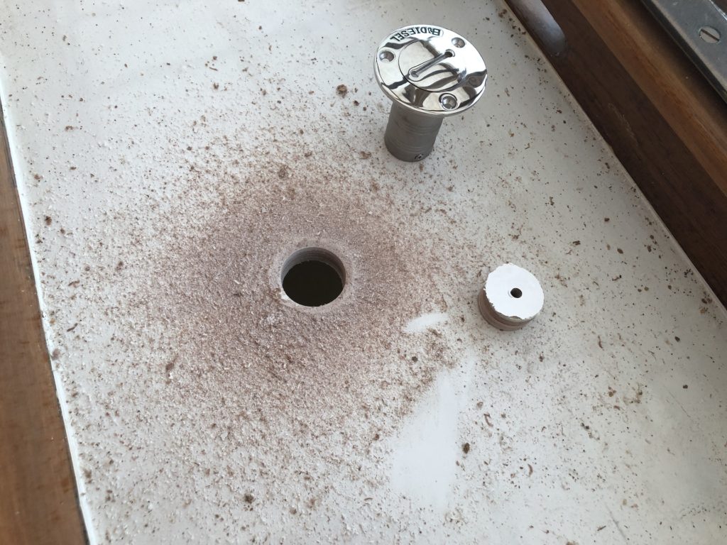
This is only a test fit:
I examined the core and was happy that it was (1) dry, and (2) tight. Recall that the deck is a plywood sandwich on fiberglass, and that I recored most of the deck back in 2012.
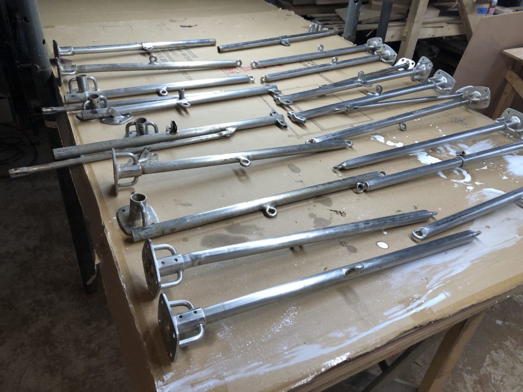
The stanchion system is a mess. There are bent stanchions, cracks in some of the tubes, and stanchion bases that cannot be removed from the tubes. I took the whole set to my metal guy, and we inspected it all together. We agreed that the best approach is a new set of stanchions and bases.
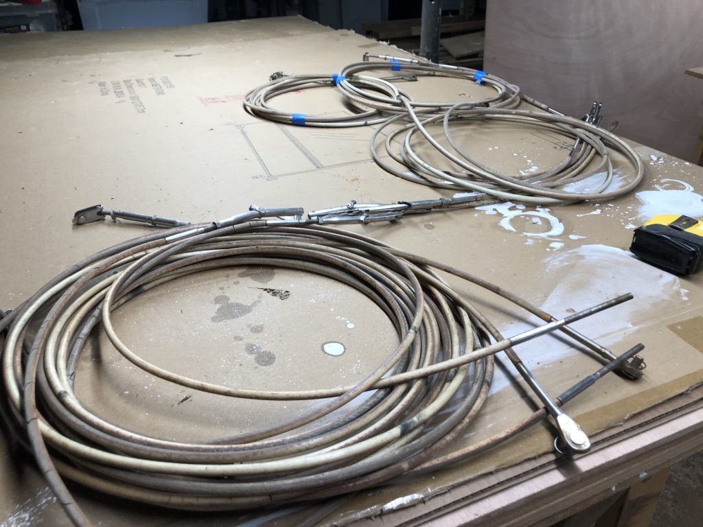
The lifelines are gross and I will get new lifelines too. A recent trend in lifelines are “rope” lifelines. These synthetic, no-stretch rope lifelines are easy to make, install, and adjust.
Another major issue is the stern pulpit. You can see it fairly clearly in this old picture from 2007:
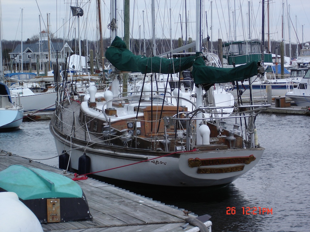
The pulpit and dinghy davits are welded together to make a single unit. Currently there are cracks in welds and tubes, and I’m going to junk it. It’s not hard to measure for a stern rail and have one made, and that’s probably what I’ll do.