5/4/14: More Time in the Bilge
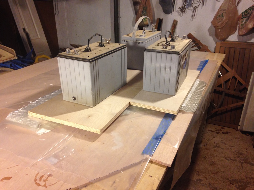
Much of the lumber for this project will be purchased at J. Gibson McIlvain. They have a wide selection of most of the woods used in marine applications. In the photo below we see a sheet of Okume marine plywood and two boards of white oak. Jamestown Distributors is the source of all kinds of materials, tools, hardware, and supplies for boatbuilding. Their clearance shelf often contains odd lengths of various kinds of fiberglass cloth.
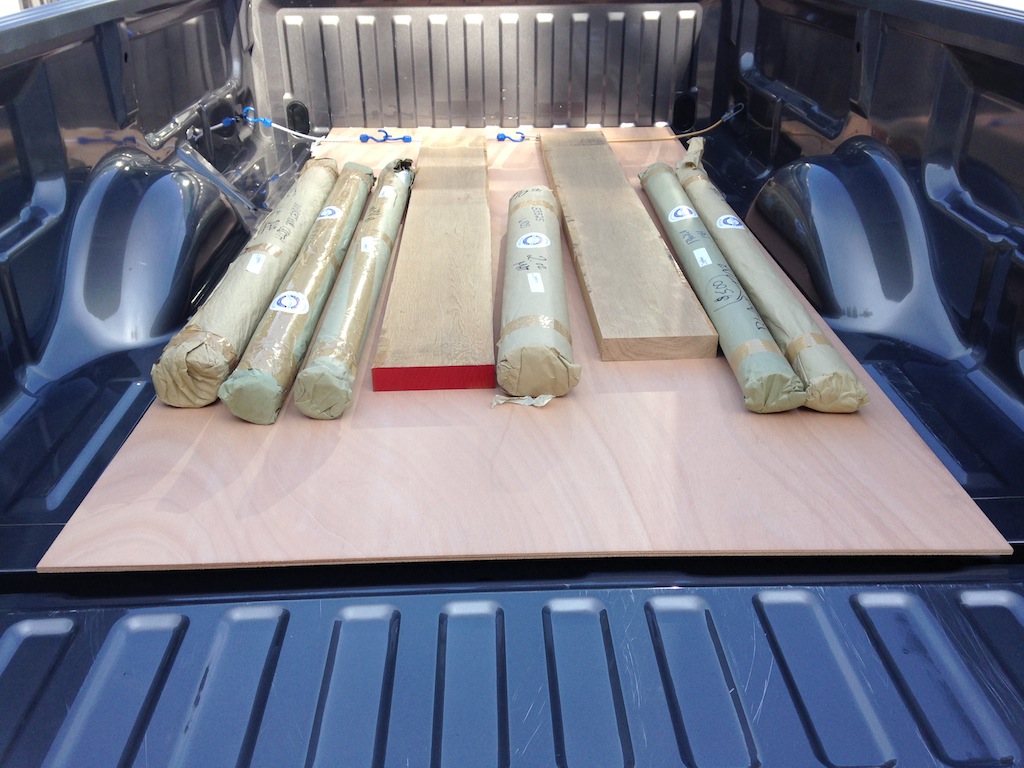
Fiberglass cloth, white oak, and marine plywood
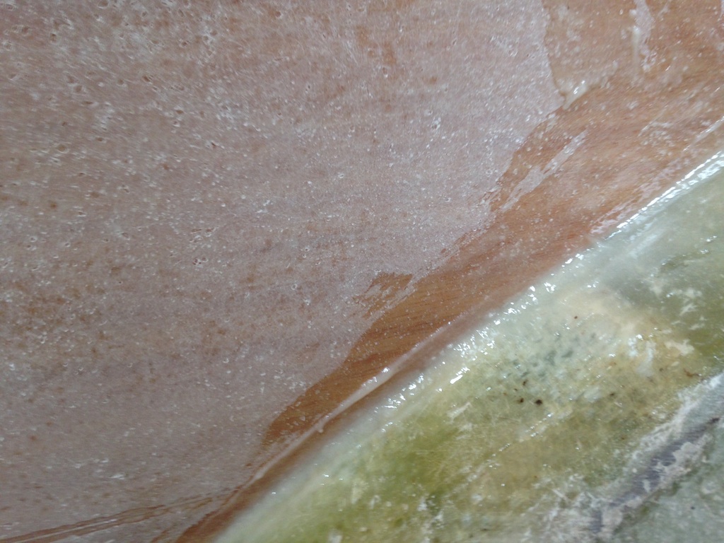
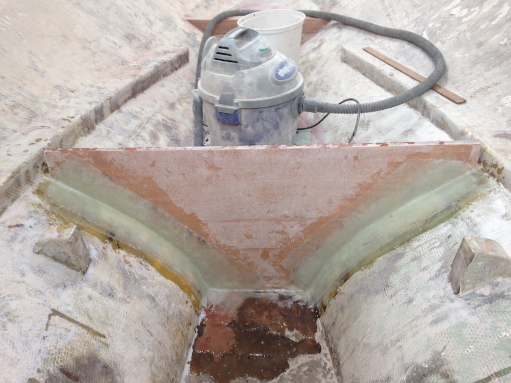
The top step of concrete has received a single layer of biaxial fiberglass, and the red areas in the photo are where thickened epoxy has been applied. A smooth surface may be achieved by several iterations of filling the low spots with thickened epoxy and sanding.
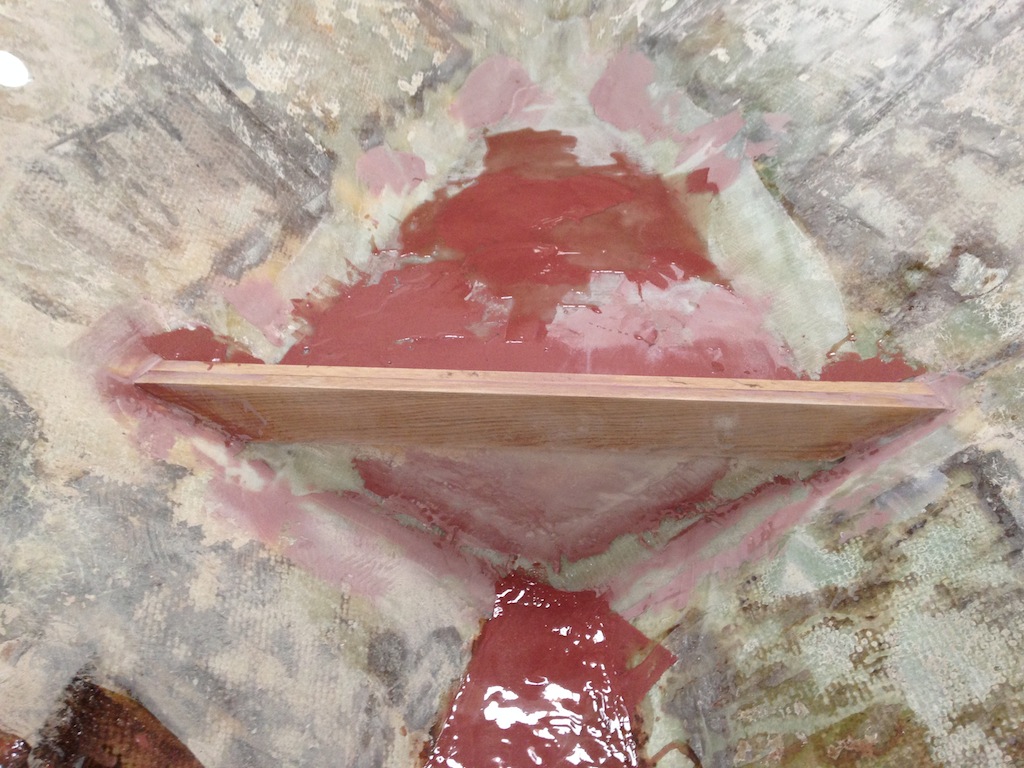
Thickened epoxy applied to the first and second steps.
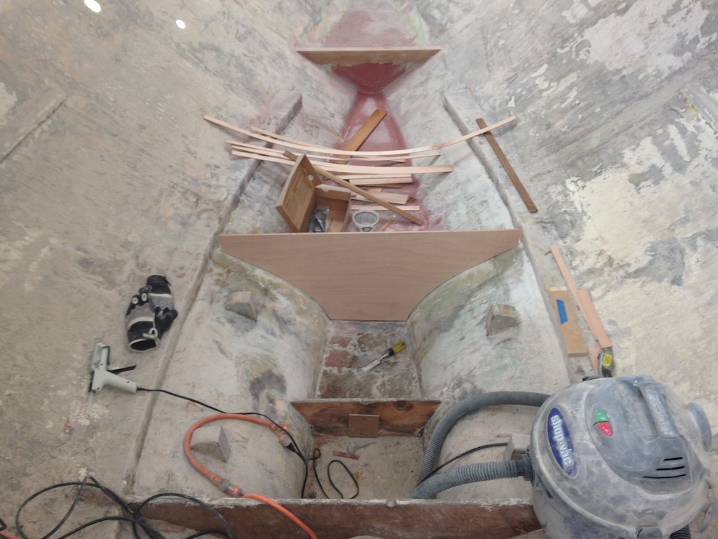
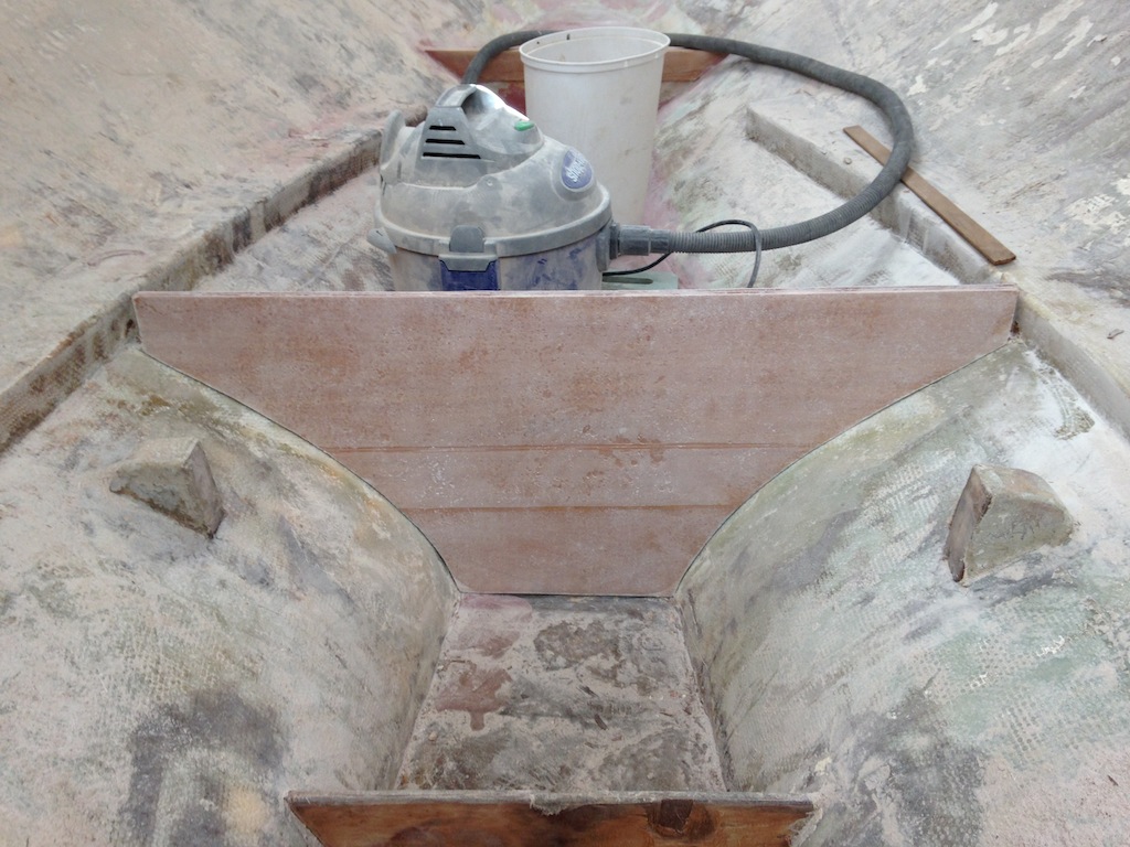
The second step of concrete was less smooth than the first, so it will be smoothed before applying the first layer of fiberglass. The bulkhead at the top of the photo below separates the second and third steps, and is one of the main characters in this post. Each of the six bulkheads that separate the seven steps was covered on both sides with fiberglass and tabbed to the hull. We have already discussed why the first and sixth bulkheads were (or will be) replaced. The other four bulkheads are in pretty good shape. The concern, though, is that the fiberglass that covered these bulkheads has trapped moisture for many years. How long should they be allowed to dry out before glassing over them and tabbing them back to the hull? Weeks, months, more? They will all be replaced.
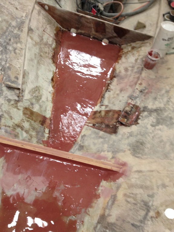
Looking down on the second step of concrete.
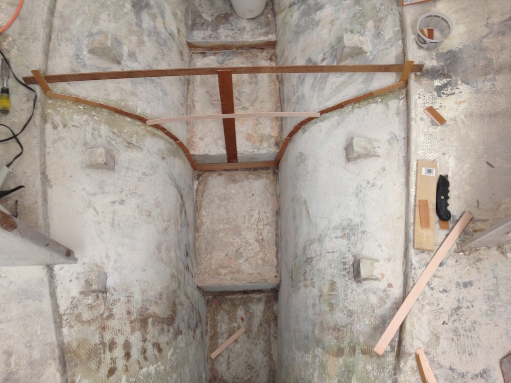
Here we see that the bulkhead that separated steps two and three has been removed and a pattern is being constructed as a template for the new bulkhead.
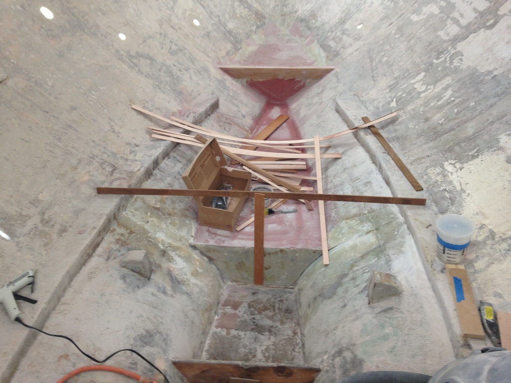
The beginnings of a pattern for the bulkhead that separates steps two and three.
Here we see the completed pattern clamped to a sheet of 3/8″ marine plywood. Okume marine plywood will be used for all plywood applications in this project. It is strong, light, and has virtually no voids. It is also expensive.
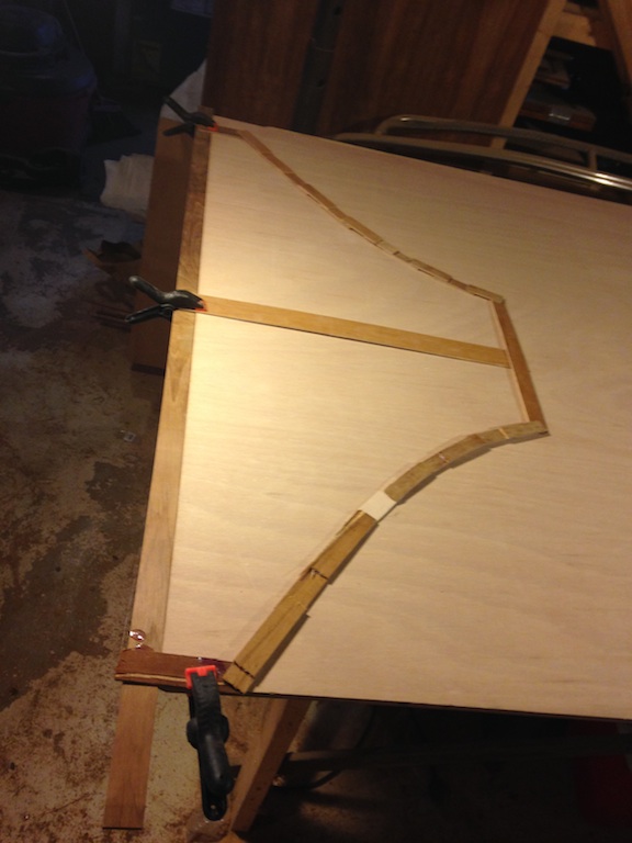
The completed pattern is transferred to the plywood by tracing its perimeter.
A good pattern and careful sawing ensures a good fit.
A good fit.
The original bulkhead was a little over 1/2″ thick. The pattern was used a second time to create a second piece, and these two pieces were laminated together to achieve the desired thickness. Here there are two pieces of fiberglass glass over plastic. The glass has been wet out with epoxy and the forward of the two bulkhead pieces is on top.
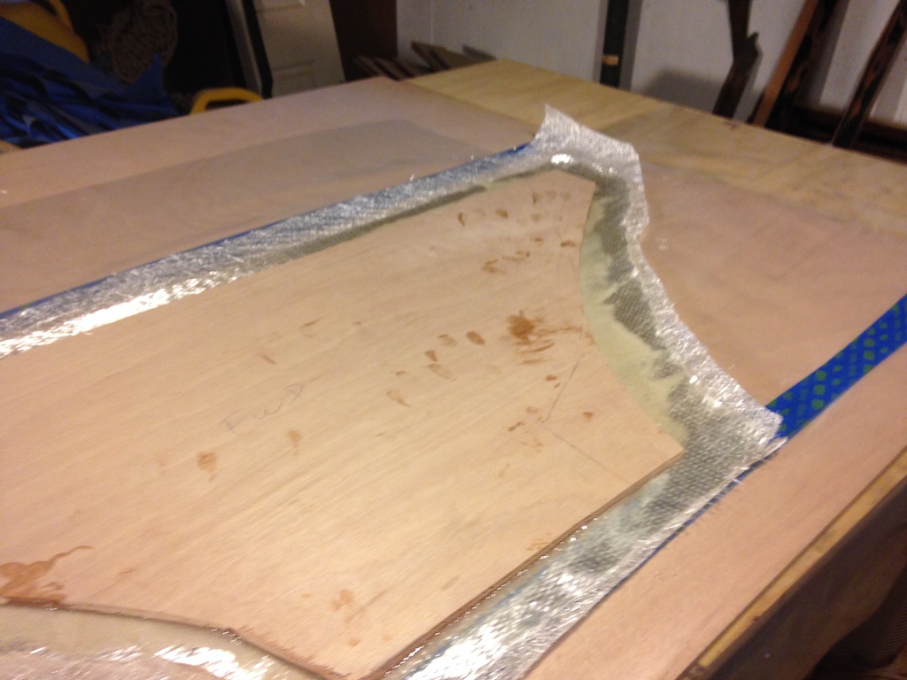
The forward piece of the two-piece bulkhead.
Here is the final layup. There are seven layers, from bottom to top, as follows: chopped-strand mat, unidirectional glass, marine plywood, biaxial glass, marine plywood, unidirectional glass, chopped-strand mat.
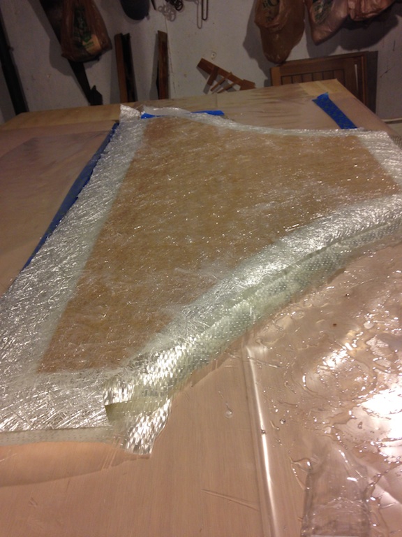
Seven layers.
This layup was covered with plastic, then plywood, then weighted down with three heavy batteries.
About 200 pounds of batteries create the pressure required for tight lamination.
Here the bulkhead is ready to be tabbed to the hull. The outer edge has been saturated with unthickened epoxy.
Ready for tabbing.
Next, a fillet of thickened epoxy was created along the edge of the bulkhead. A fillet not only “softens the bend” in the fiberglass tape (which promotes strength and minimizes air pockets), but gives the bulkhead a larger “footprint” on the hull. It was found (after the photo below was taken) that a throwaway plastic spoon is an ideal tool. The back of the spoon can be run along the fillet, making a nice, wide radius. Then the front of the spoon can be used to scrape up the leftovers. The hardest part was actually getting the thickened epoxy into the corner. Throwaway pastry bags might be the ideal solution.
A fillet of thickened epoxy eases the bend in the fiberglass.
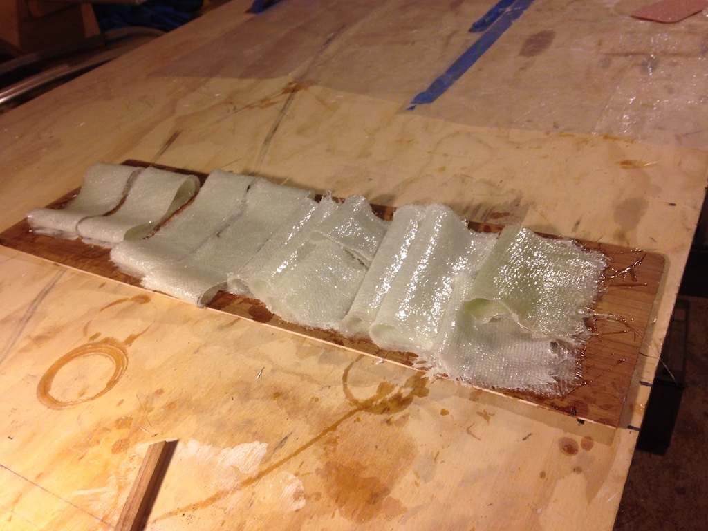
The tabbing was cut from biaxial fiberglass cloth. Everything was wet out in advance, as shown below.
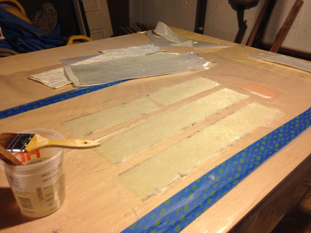
Wetting out the glass.
The fiberglass strips are placed on a cheap board, on which they will be carried to the boat.
Ready to be moved to the boat.
The next photo shows the aft side of the bulkhead with three layers of tabbing.
The aft side of the bulkhead.
Here we see that none of the original bulkheads remain (except the parts of them that extend down into the keel who-knows-how-far). The bulkhead at the top of the photo is the one that we have been discussing. It is one of three bulkheads in the bilges whose top is about even with the lower stringers.

Steps 2-7 (top to bottom in the photo)
The hot glue gun and doorskin were employed once again to make the pattern in the photo below. It takes about 20 minutes to make such a pattern.
A pattern for the middle of the three big bilge bulkheads.
In the photo below, the little bulkhead has three layers of tabbing, while the large one (bottom) has only two. There wasn’t enough epoxy or biaxial cloth to continue, but more layers will be added shortly.

The bilges take shape
A floor timber runs along each of these big bilge bulkheads. The photo below shows a new timber alongside its old counterpart.
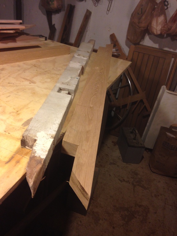
Making a new floor timber.
Strings are used to establish the level of the top of each timber. Here the strings are touching the top, so material must be removed from the ends, as appropriate. Finding the right level by many iterations of removing material, then testing, seemed like the least efficient route. The decision was made to simply remove more than enough material, then establish the proper level by other means.
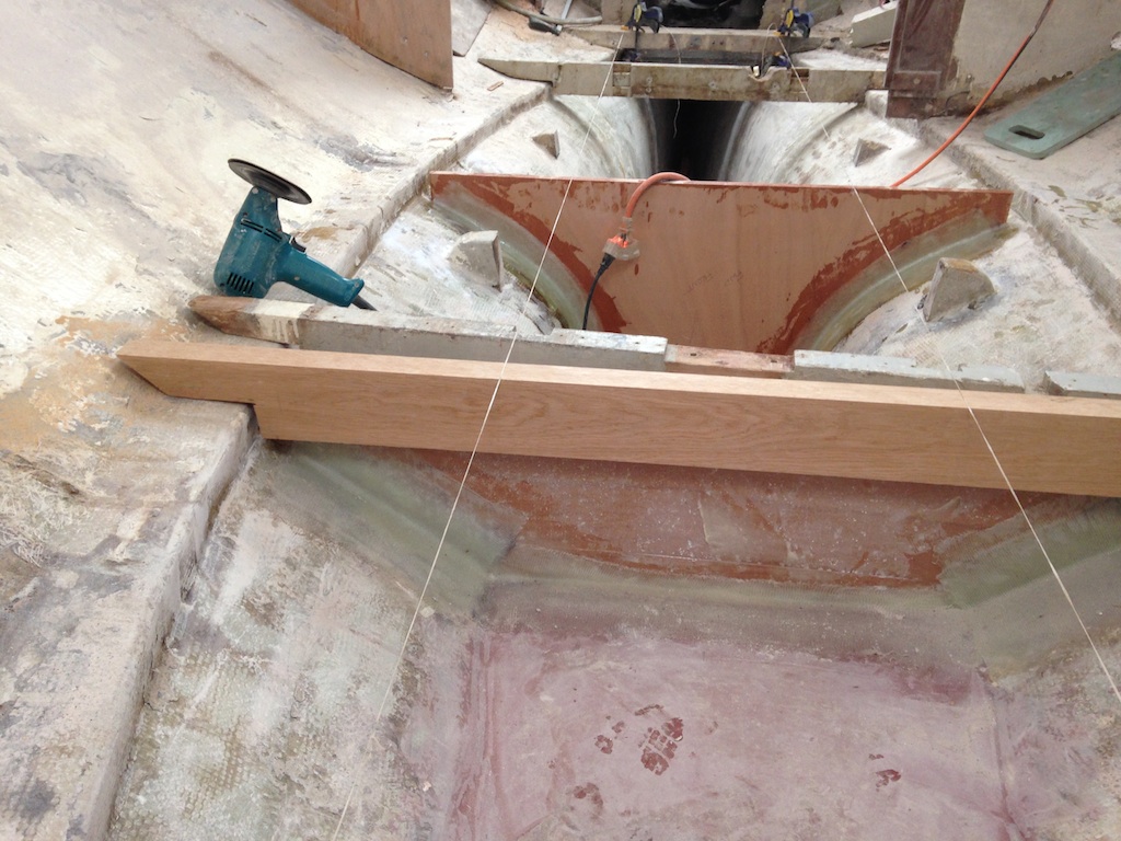
The strings are touching the new wood.
In the following photo, the stacked dado set on the table saw is being used to remove more material from the ends of the new floor timber.
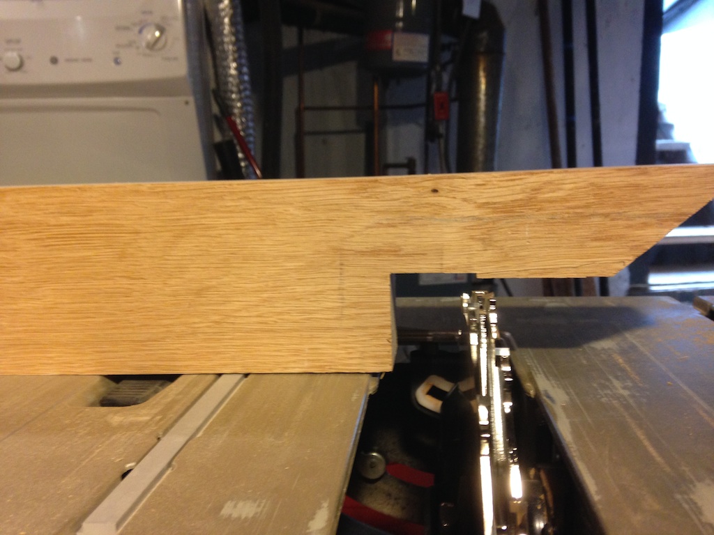
The stacked dado set12