5/15/14: Floors, Engine, and Engine Compartment
The floor timbers will be replaced. Most of the old wood is rot-free, so it might be recycled and used elsewhere.
The floor timbers
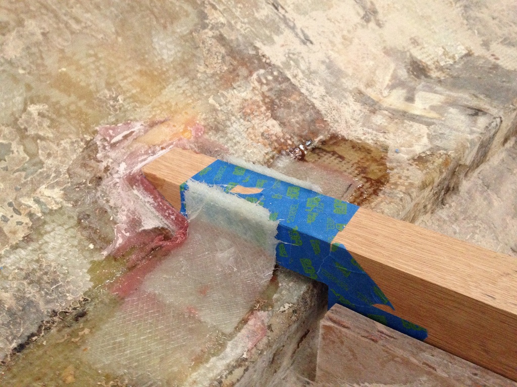
We have discussed the difficulty in establishing the correct level of the tops of these timbers. In the following photo, two timbers have been clamped to bulkheads so that their tops just touch the leveling strings. The ends of the timbers are taped off, and thickened epoxy has been forced into the gap between the ends of the timbers and the hull/stringer.
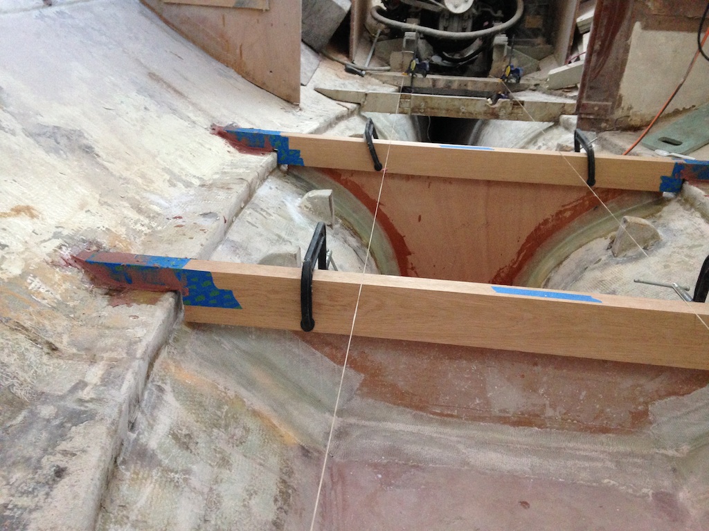
Two of the big timbers clamped to bulkheads
In the following photo, the epoxy has dried, and the excess has been cut away. What’s left are pads that make perfect fits to the ends of the timbers and keep the timbers at the correct vertical level.
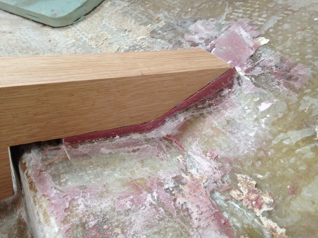
These epoxy pads establish the correct level of the floor timbers.
To keep the floor timbers on their pads, fiberglass supports were created that keep the ends of the timbers from moving fore and aft. Eventually, the main timbers will be connected to the hull (more or less permanently), but for now they must be removable.
One end of a floor timber
Recall that sealing the bilges with epoxy and fiberglass is one of the more pressing issues. The engine must be moved into the cabin to gain full access to the space in the bilge. The following photo shows a box of “engine stuff” that was stripped from the engine before moving.
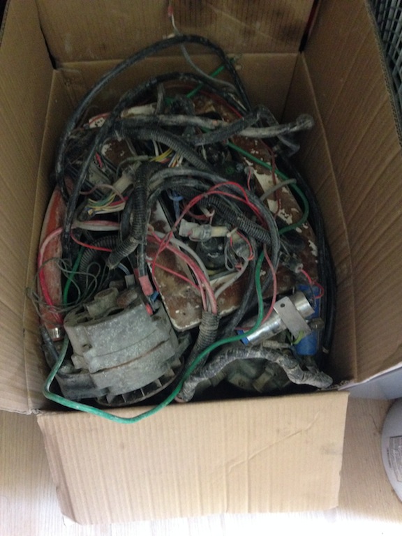
Engine stuff
A temporary floor was built of cheap plywood and two-by-fours. A “come along,” lines, a block, a chain, various shackles, two of the old compression posts, clamps, and a piece of oak were used in the rig that was used to lift and move the engine.
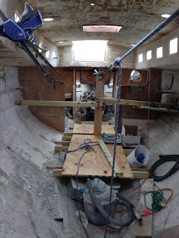
A temporary floor and the rigging used to move the engine
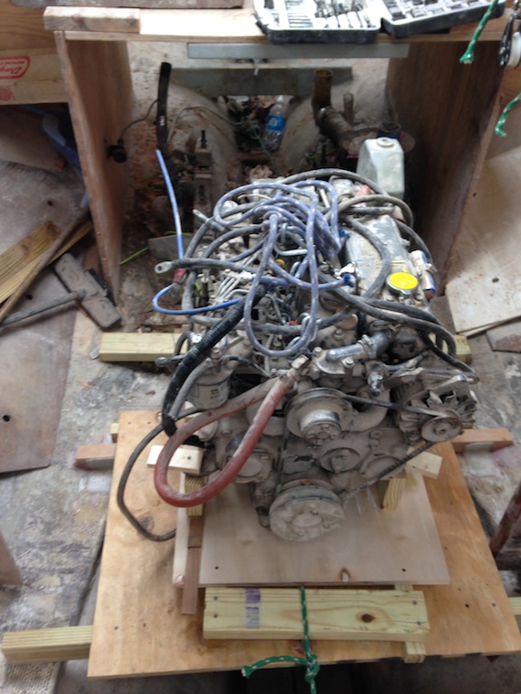
The engine is a Yanmar diesel, model 4JH-HTE. It is a big, heavy engine, and at 75-hp is a little more than a 40-foot sailboat needs. Nevertheless, the engine will be refurbished and reused.
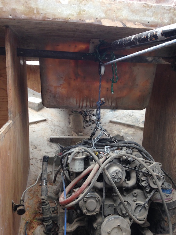
The Yanmar 4JH-HTE
The following photo shows the engine after being removed from its mounts. The come along was used again to slide the engine forward another five feet.
The engine is off its mounts and into the cabin.
Here we have a first unobstructed look at the engine bed and surrounding area. The muffler and part of the exhaust are on the port side (right side of the photo), while the raw water intake is on the starboard side. The four engine mounts are in good condition, so they will be reused. (A new replacement set costs about $1000.)
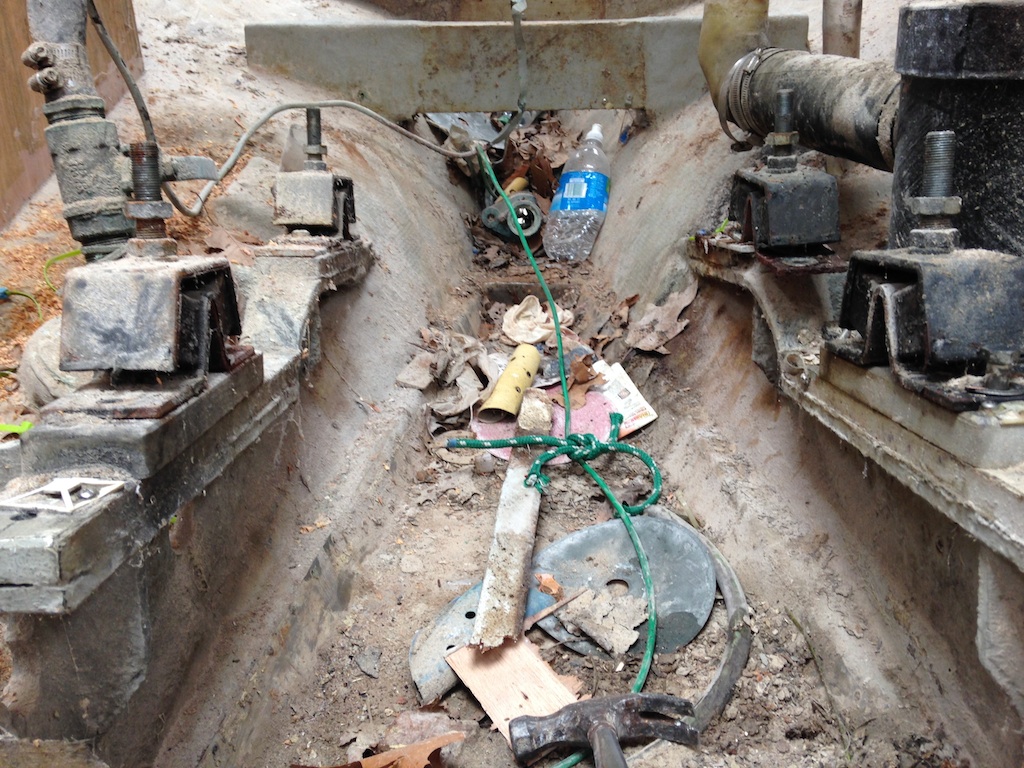
The engine bed
The drip pan is responsible for catching whatever finds its way under the engine. It guides liquids to a single hole, which minimizes the mess in the bilge.
The drip pan coming off its supports
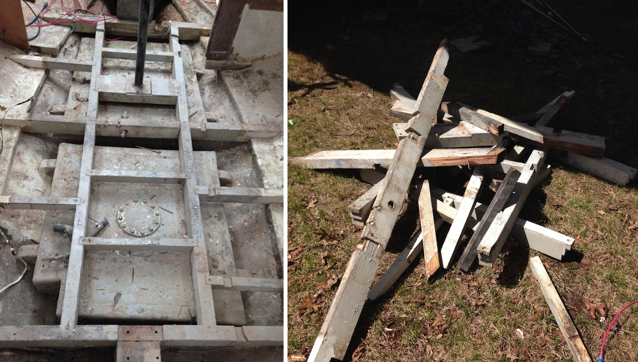
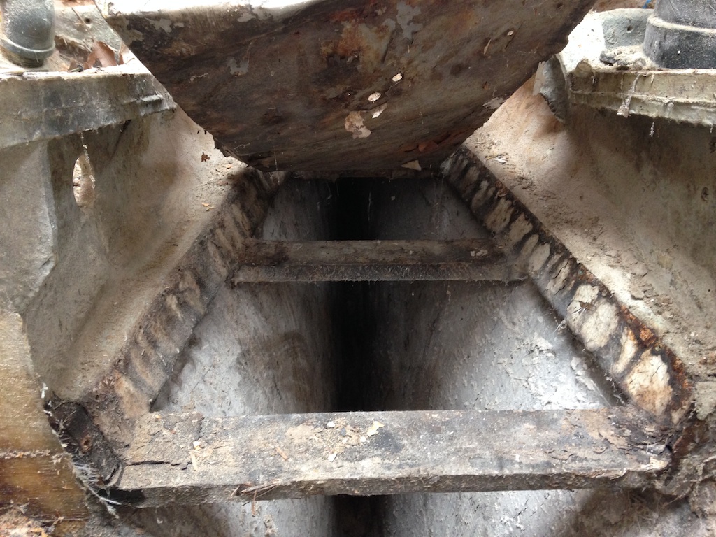
The structure supporting the drip pan was very robust, as shown below. The drip pan was stainless steel and was attached to this structure with small nails. It’s unlikely that this arrangement represented an important structural member of the boat, but the new drip pan and its supports will be designed to duplicate the structural integrity provided by the old system.
The support structure of the old drop pan
The propellor shaft passes through the stern tube. Free access to both ends of the stern tube occurs very infrequently, so removing and replacing is the plan. Stern tubes and cutlass bearings are notorious for being near-impossible to remove. In the photo below, chisels have been used to move the tube inboard by about 1/2 inch, and the come along and a line are pulling the tube inboard.
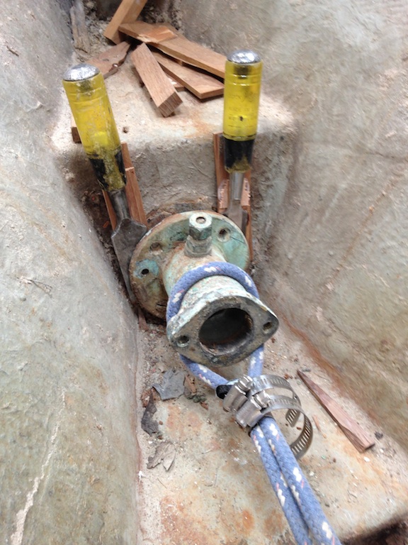
Stern tube removal
This method was not sufficient, so an attempt was made to push the stern tube into the boat from the outside. In the photo below, a compression post that has been cut in half is pushing in on the stern tube. A large log was used as a sort of battering ram, and gradually the stern tube gave way.
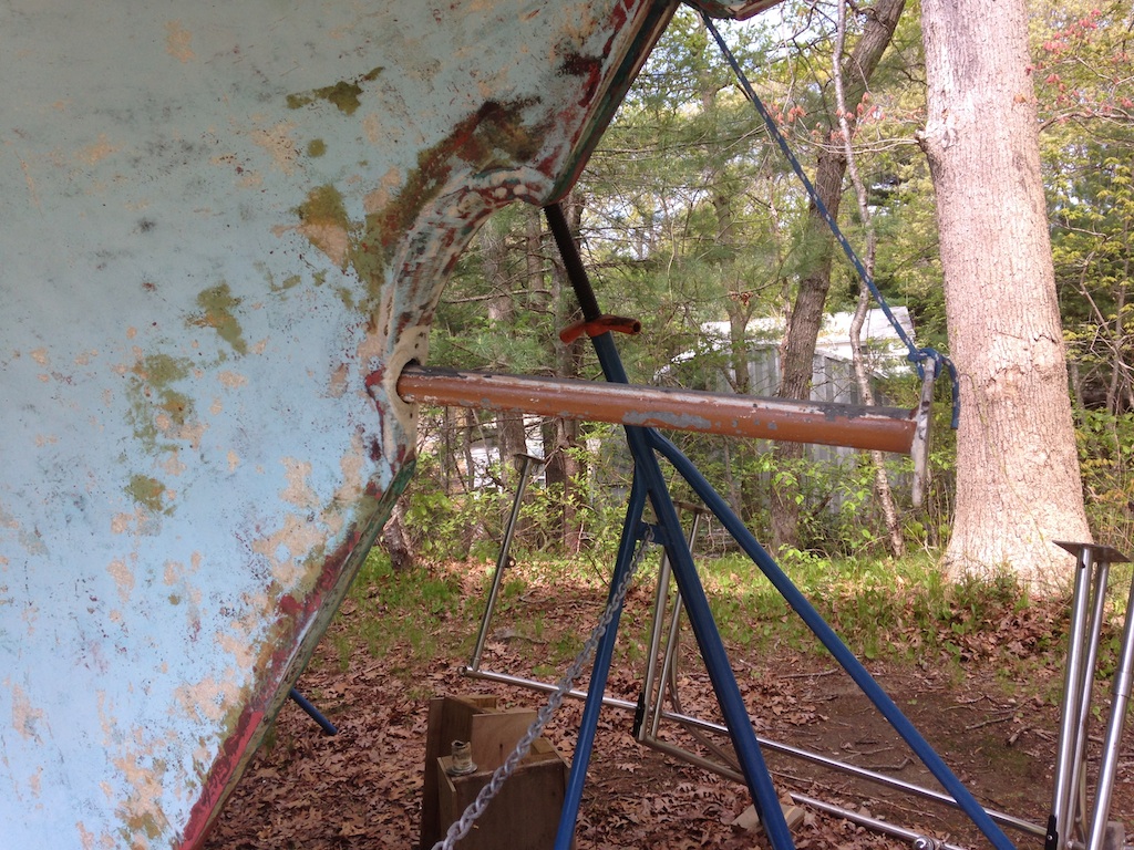
A compression post pushes the stern tube into the boat.
The following photo shows the stern tube after removal.
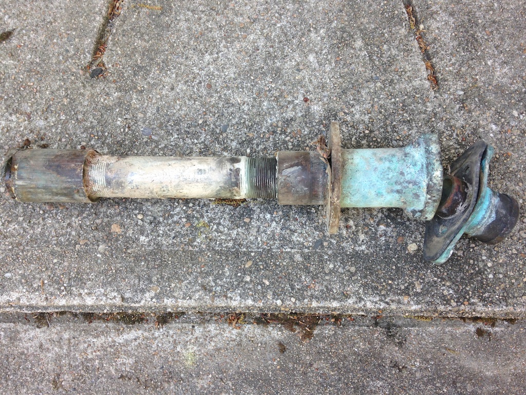
The stern tube
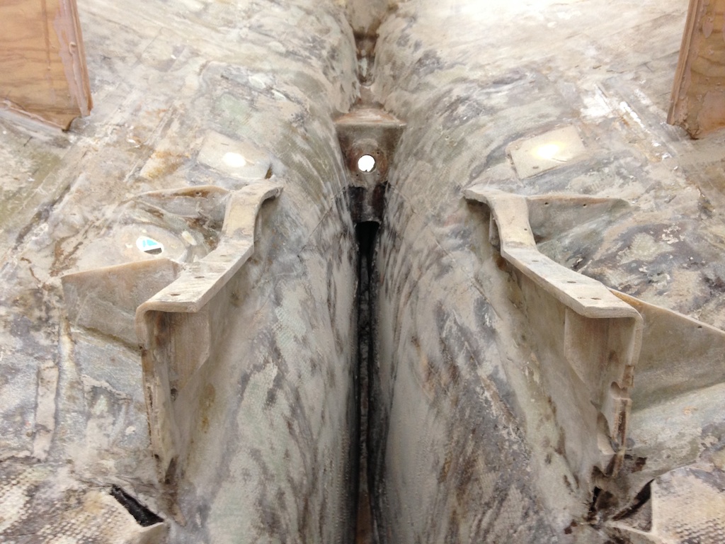
The next photo is looking aft at the engine bed. Note that the stern tube, drip pan, and motor mounts are gone. The forward motor mounts sat on teak boards, which sat on the fiberglass engine support.
The engine bed
The aft motor mounts sat on steel plates that were bolted to the engine support in their middle. These plates sit on teak boards, which sit on the fiberglass engine support. These metal plates were necessary because there is no room to through-bolt the aft part of the aft motor mounts. The photo below shows that a nut has been welded to the bottom of one of the metal plates. This nut lies in the circular hole in the wood and a short bolt is used to secure the aft end of the motor mount. These metal plates will be reused, but the teak boards will all be replaced.
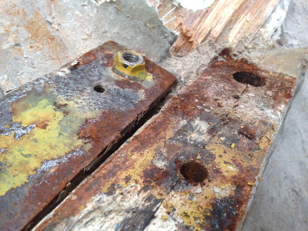
The bottom of the starboard metal plate
The two bulkheads that flank the starboard and port sides of the engine compartment are too close to the engine. They were replaced a few years ago, but they are still too close, and they will be replaced again, this time with the best quality plywood. The new bulkheads will be 3.5 inches outboard of their original positions. The following photo shows how a two-by-four and a straight edge were used to establish the position of the not-yet-built bulkheads.
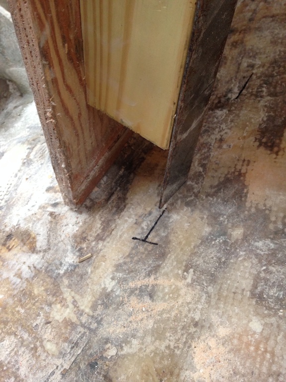
Establishing the positions of the new bulkheads
The next photo shows the situation after the two bulkheads have been removed and a lot of sanding has been done, including sanding the fiberglass engine support. The two holes on the starboard side are a cockpit drain (aft) and the raw water intake (forward). On the port side is the other cockpit drain. These through hulls are all too close to the engine and will be moved. The cockpit drains will be moved aft about one foot and the raw water intake will be moved outboard about six inches.
Cleaning up the engine bed
Plugging up a through hull requires that the hull be ground down in a beveled circle, so that fiberglass can be laid up as the hull is rebuilt to its original thickness. The following photo shows one of the cockpit drain holes from the outside, after grinding.
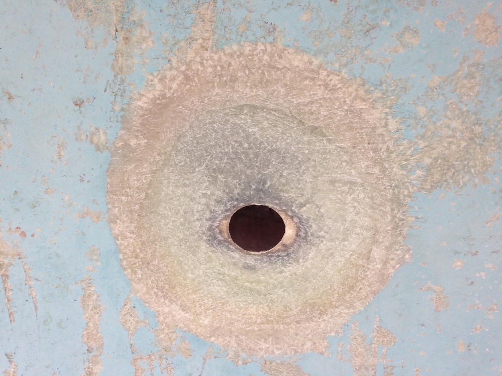
Almost ready for fiberglass
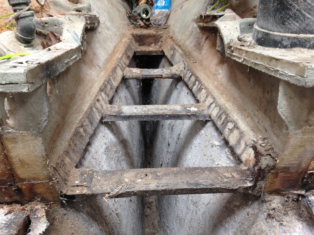
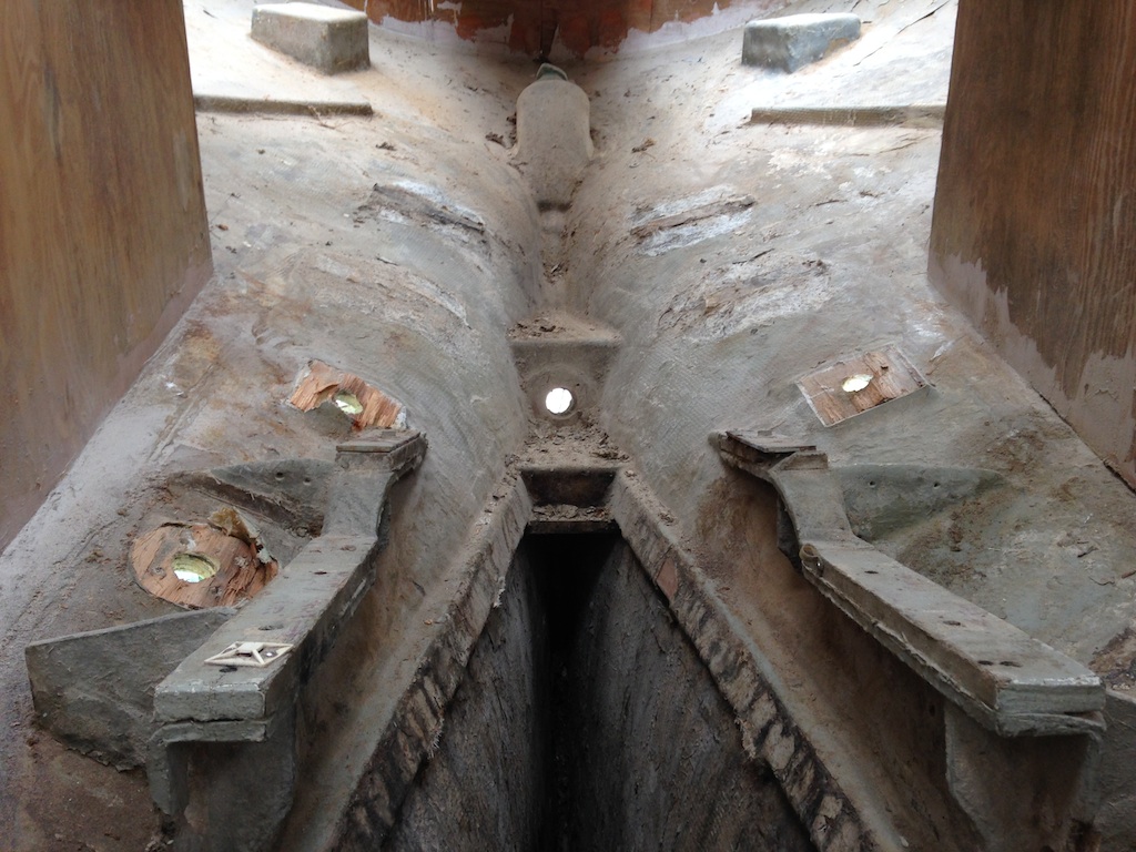
The following photo shows the dark, empty space under the stern tube area. Inaccessible spaces are undesirable. Moreover, the deepest parts of these spaces are too narrow to reach with sanding tools. (Hand sanding, however, is possible.) One solution might be to install a series of mini bulkheads and fill the deepest spaces with a mixture of epoxy and some sort of low-density filler (chopped up pieces of foam perhaps). The total volume of these spaces may amount to only a gallon or so.
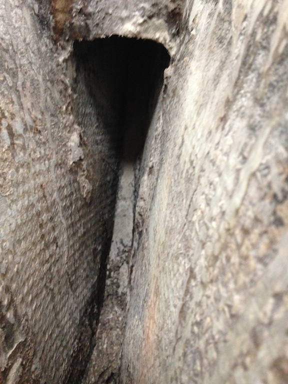
The deepest recess in the boat
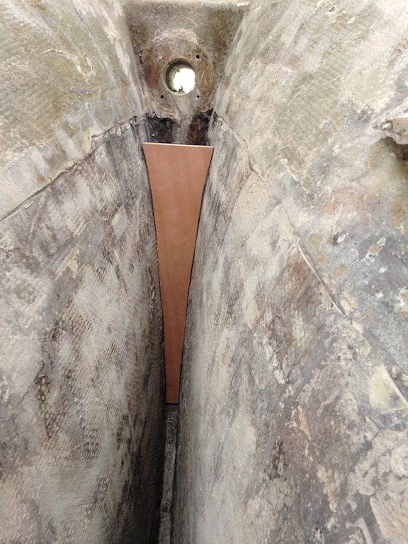
The following photo shows a pattern being constructed for one of the proposed mini bulkheads.
A pattern for a mini bulkhead
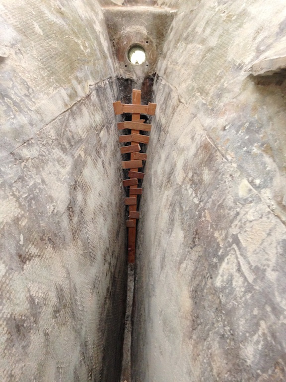
The next photo shows the mini bulkhead being test-fitted. These bulkheads, as well as the epoxy filler, would provide some structural support as well as eliminate some inaccessible spaces. Additional advice will be solicited before moving forward with this part of the plan.