6/2/14: Bilge, Main Bulkhead, and Compression Posts
Interlux Bilgekote marine paint is formulated to prevent the absorption of oily substances by wood and fiberglass. For now, only the area below the drip pan will be painted. The photo below shows where the gray Bilgekote has been applied.
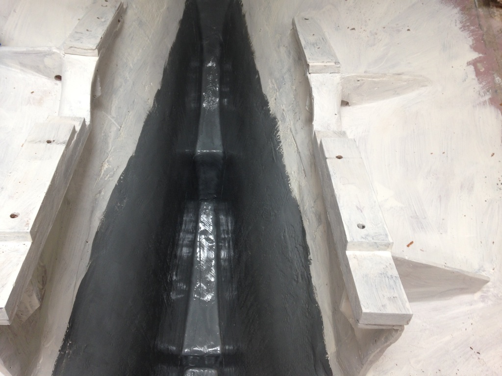
Two coats of Bilgekote
The drip pan will make access to this area difficult, so plastic and tape was used to form a drip catcher, which may be removed easily after the drip pan is in place and the epoxy has dried.
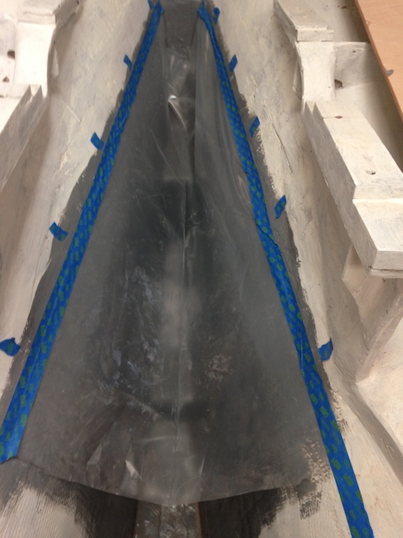
A drip catcher
The next photo shows the drip pan fitted into place. A fillet of thickened epoxy will be run around the perimeter and then fiberglass tabbing will finish the installation (accompanied by plenty of sanding, priming, and painting). The bottom of the drip pan, which cannot be seen here, has already been primed and painted.
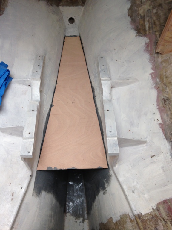
The drip pan
Other projects were undertaken while various applications of paint and epoxy dried. The main bulkheads were cut from 3/4-inch Okume marine plywood. As we have seen, the main bulkheads were more-or-less intact after removal, so they were used as templates for the new bulkheads. The smaller of the two main bulkheads is on the starboard side, and the photo below shows the original (right) and the new (left).
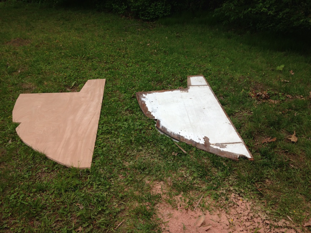
The starboard main bulkhead
As we have seen, the port main bulkhead was cut in two pieces because it was too big to fit out of the companionway. Thus, the new port main bulkhead must also be constructed of two pieces. The table saw with the dado set was used to make a rabbet along one edge of each piece of plywood. Working with large pieces on a small table-saw is difficult and the rabbets needed some cleaning up. A bullnose plane (also called a rabbet plane) was used for this cleaning. The special feature of a bullnose plane is that the blade spans the entire width of the plane, which allows the corner of the rabbet to be shaved.
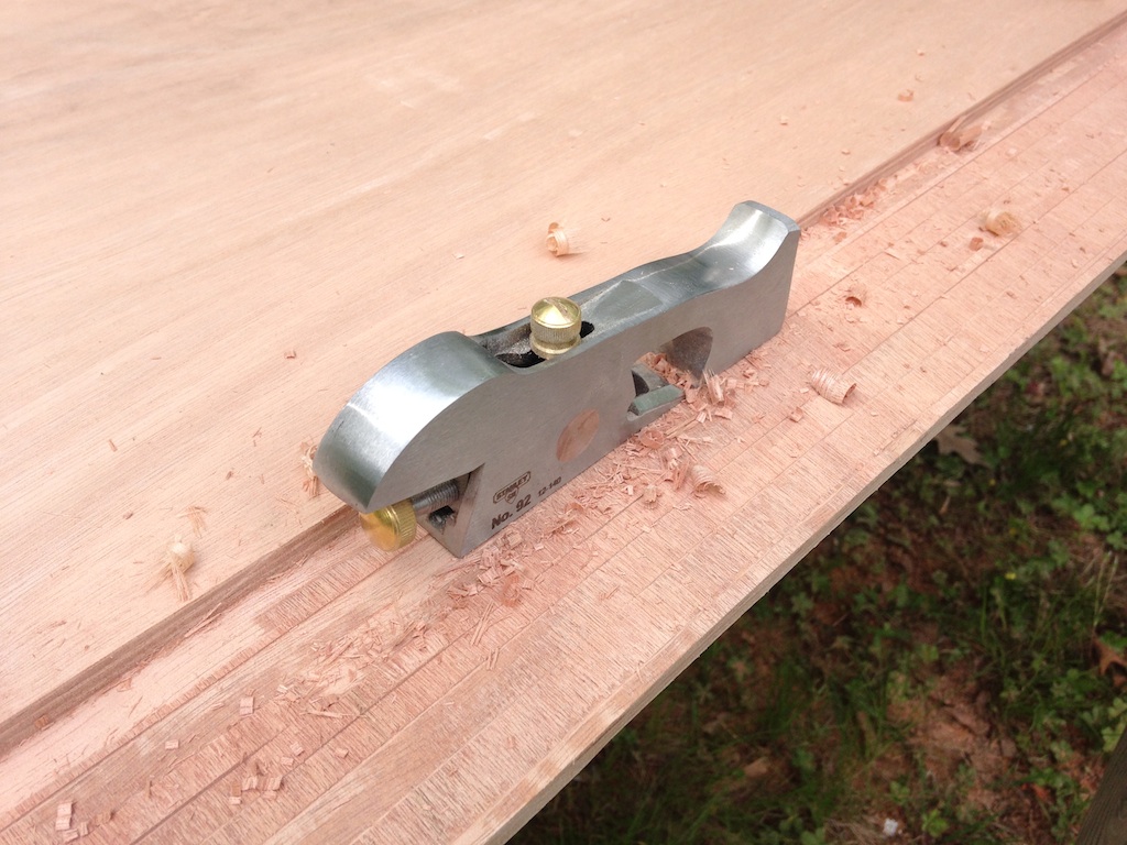
Planing the rabbet that joins the two pieces of the port main bulkhead
The photo below shows the port main bulkhead (in two pieces) placed on the two pieces of new plywood. Look closely for the rabbet.
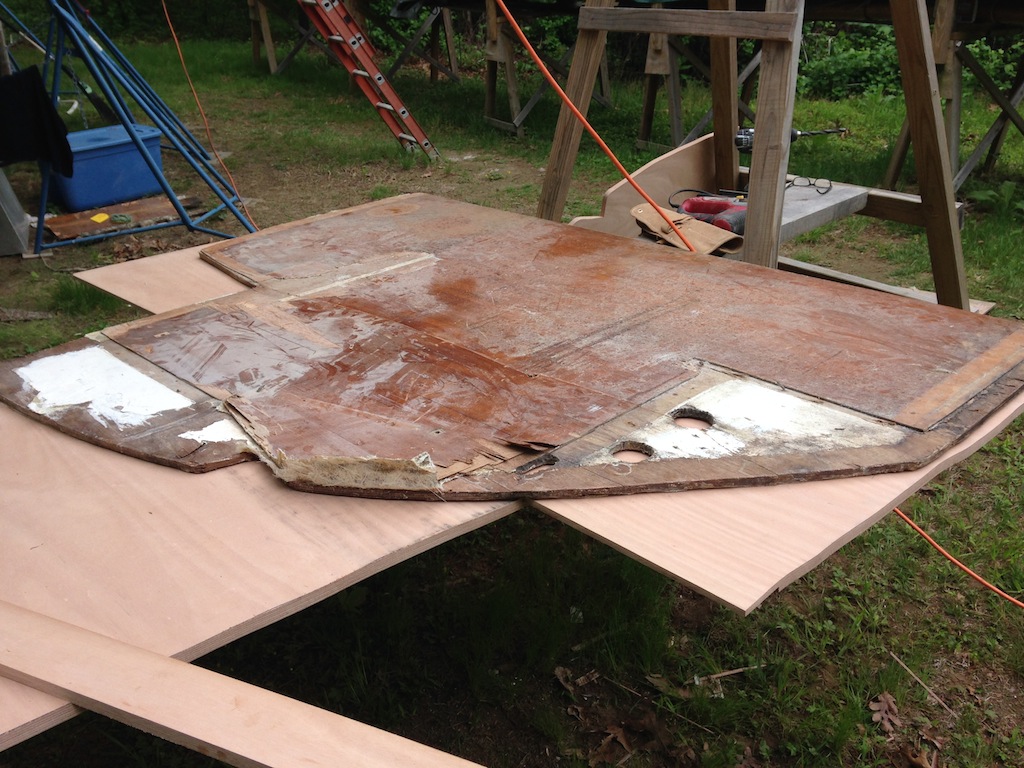
The port main bulkhead being used as a template
The pattern was traced, and the pieces were cut, as shown below. These pieces were moved into the cabin, and then joined by using thickened epoxy in the rabbets and bolts to hold everything together.
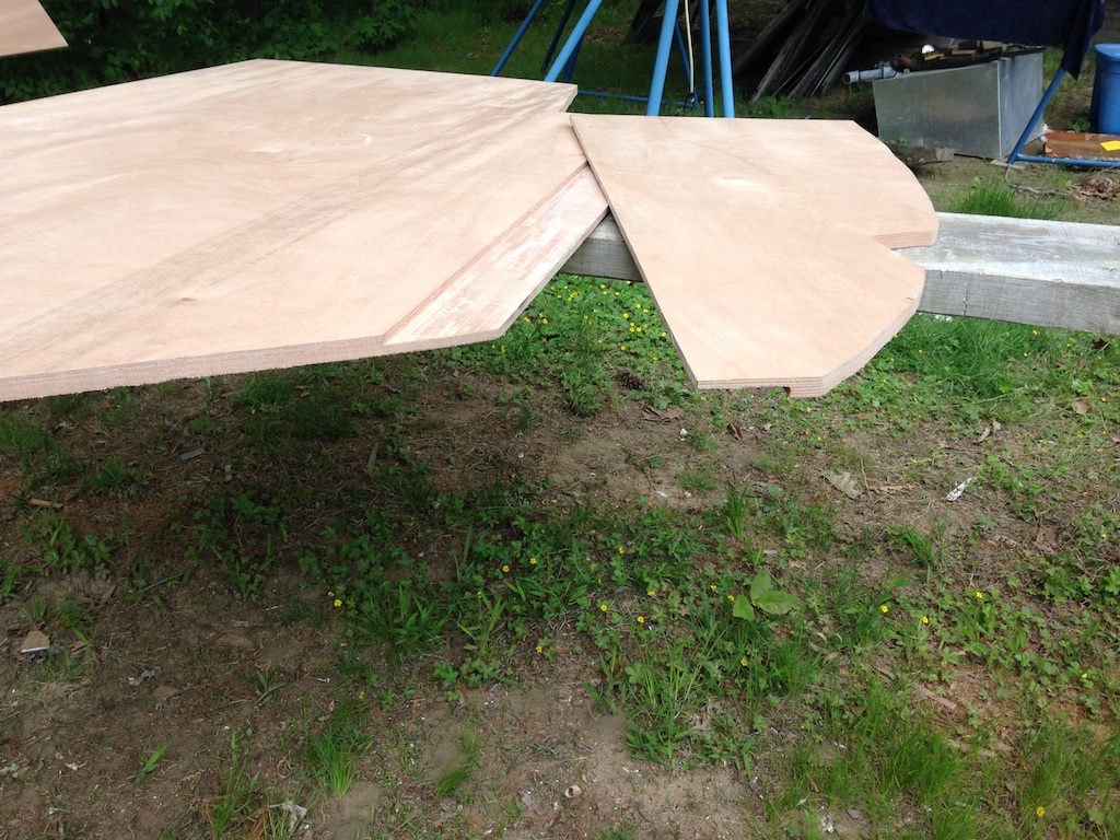
The port main bulkhead in two pieces
The main bulkheads must be parallel to each other and vertical. The inboard edges of each bulkhead, that define what will be the doorway to the head, must also be parallel. The only remaining original bulkhead (shown below) is the one that separated the port-side salon with the galley area. The vertical edge of this bulkhead was used as one reference and the mainsheet track in the aft part of the cockpit was used as a another. These two reference lines should be vertical and horizontal, respectively when the boat is level. Using a plumb bob and a level, it was easy to see that the boat was, in fact, not level, but listing port a few degrees. About an hour of tweaking the jack stands and checking the reference lines corrected the situation.
The only remaining original bulkhead
The photo below shows the two main bulkheads fitted temporarily.
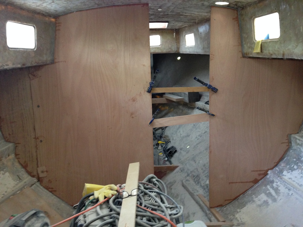
A first attempt at aligning the main bulkheads
Several iterations of set up, take down, trim edges, followed by clamping, blocking, shimming, etc., resulted in perfect alignment. Long boards clamped across both bulkheads established that they were parallel. The plumb bob established that they were vertical. A tape measure established that the width of the “doorway” was exactly 22.25 inches from top to bottom.
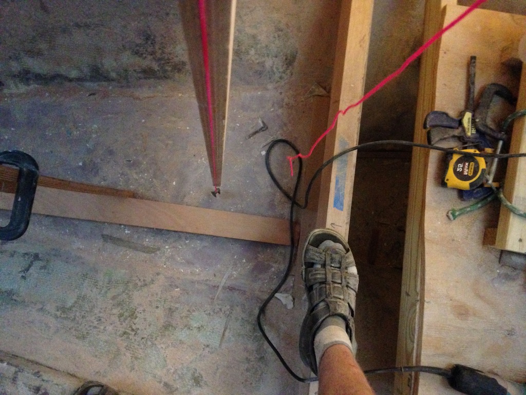
Establishing verticality using the plumb bob
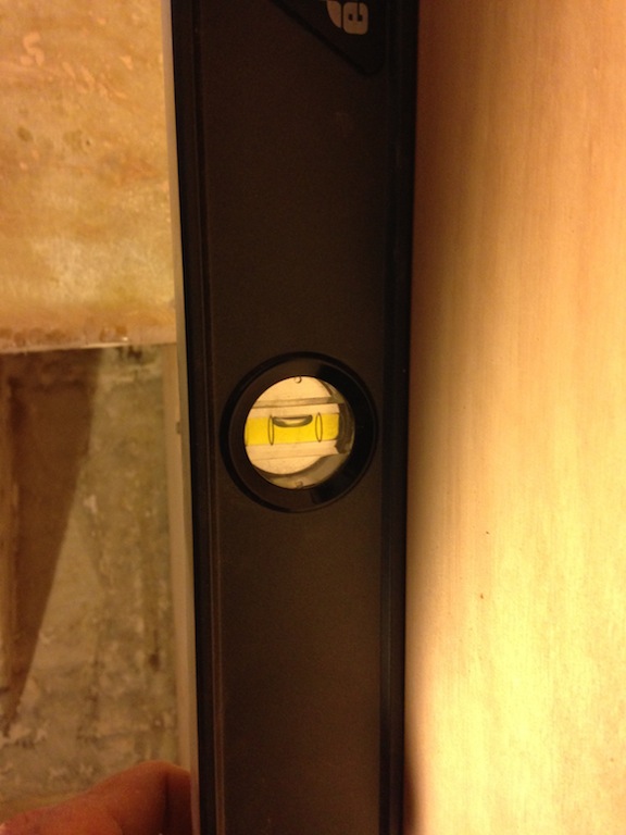
Checking verticality using the level
A fillet of thickened epoxy was created along the top and outboard perimeters of the bulkheads. This fillet, once dry, bonded the bulkheads to the hull and the clamps, blocks, and shims were removed. The seams were “taped” using three layers of biaxial fiberglass–8 inches, followed by 6 inches, followed be four inches.
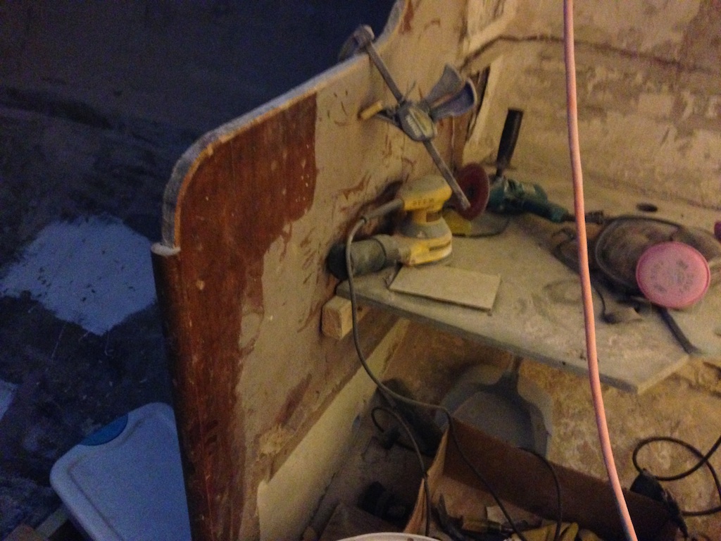
Taping the seams starts by measuring the seams, then working out suitable lengths and shapes for the fiberglass strips. The fiberglass is wetted out in advance in the basement. A throwaway brush is used to apply epoxy to the cloth. A surprising amount of time and effort is required to fully saturate the cloth. A surprising amount of epoxy is absorbed by the cloth (about 2-2.5 gallons for these bulkheads). A grooved roller is used to work out bubbles and a plastic spreader is used to wipe away excess epoxy.
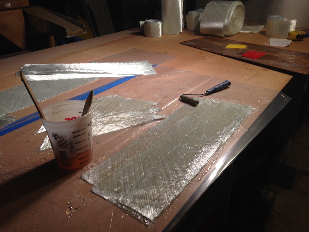
Some of the tools used in laminating
On the boat, the strips are laid into place, widest first, and air bubbles are worked out with the plastic spreader, the roller, and gloved hands.
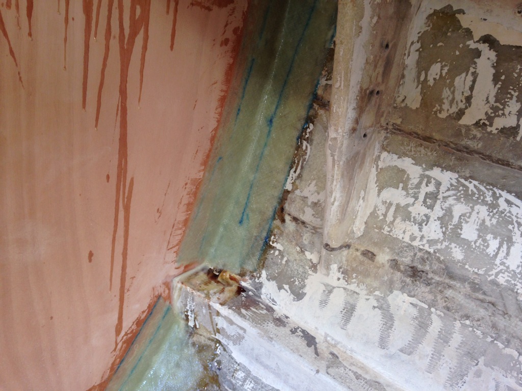
Fiberglass tabbing on the starboard main bulkhead

The tabbing at the top of the port main bulkhead
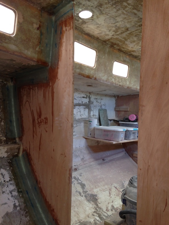
Looking aft at the starboard main bulkhead
Once the tabbing is cured, it is sanded lightly. The tabbing stands “proud” (a woodworking term–look it up) of the bulkhead, and is wider than whatever molding will decorate the seam. A question that arises: will this situation will be objectionable from the standpoint of aesthetics? For now, thickened epoxy was applied, which when sanded, will smooth the irregularities in the tabbing and perhaps make the transition from tabbing to bulkhead virtually invisible. The original bulkhead had a thin layer of veneer that covered most of the bulkhead and hid whatever tabbing extended beyond the molding. The disadvantage to this arrangement, of course, is that the veneer might camouflage loose tabbing. In Thalassa, much of the tabbing had released from the main bulkheads, but none had lost their grip on the hull.
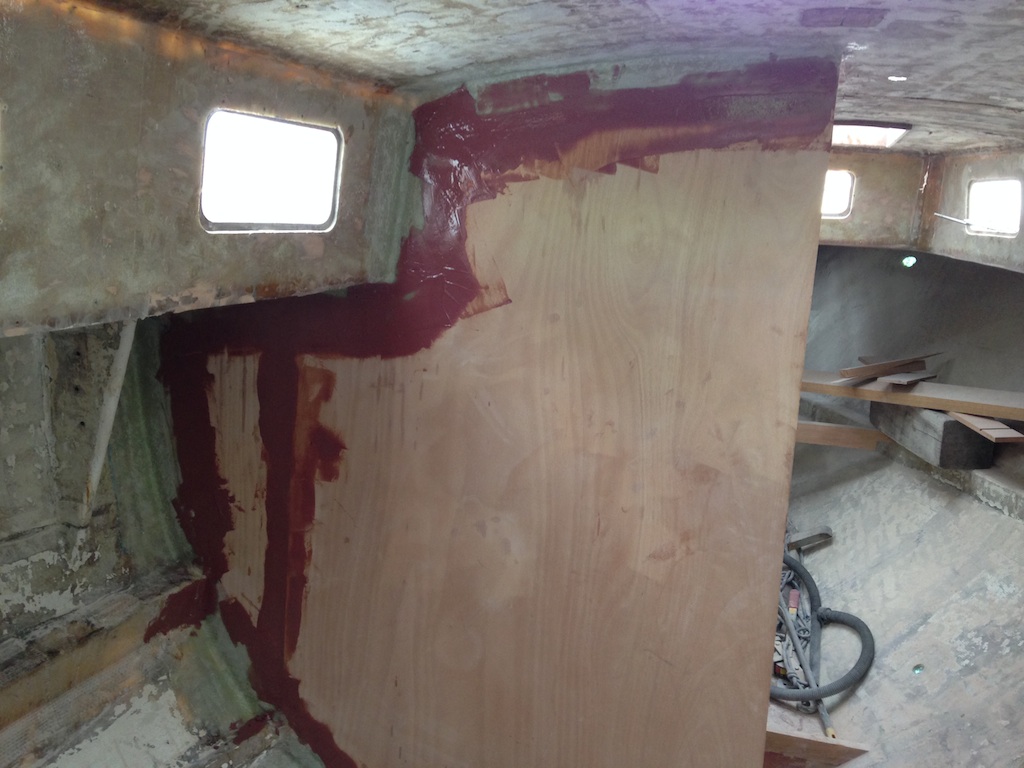
Thickened epoxy applied to the dry tabbing
Meanwhile, new compression posts have been made. The following photo (courtesy of the Mystic Seaport Archives) shows the calculations made by designer Philip Rhodes related to the original compression posts. You can see that, even with the usual safety margins, he was “not quite OK” with the strength of the forward compression post.
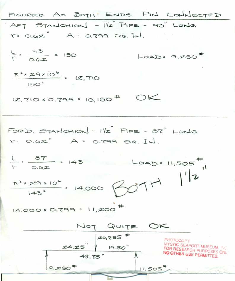
Compression posts calculations
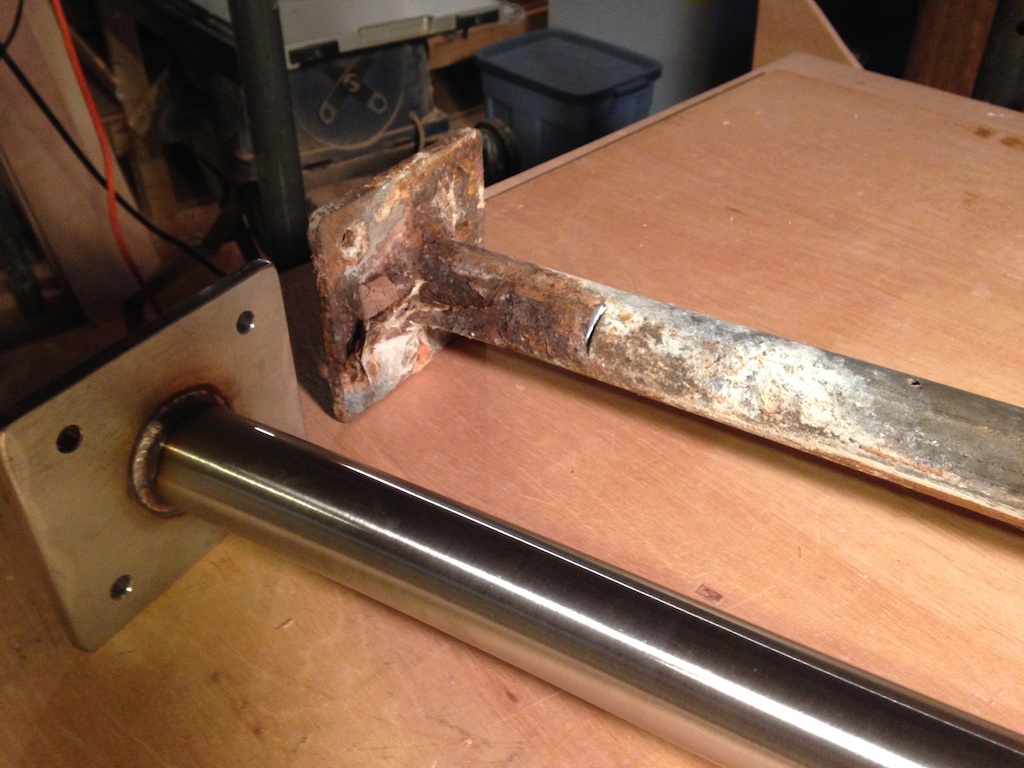
The new compression posts have the same outside diameter, but there are two key differences: they are stainless steel (304), and they are made from “schedule 80” pipe, which has a larger wall thickness. One of the old posts weighs 21 lbs, while its new counterpart weighs 31 lbs.
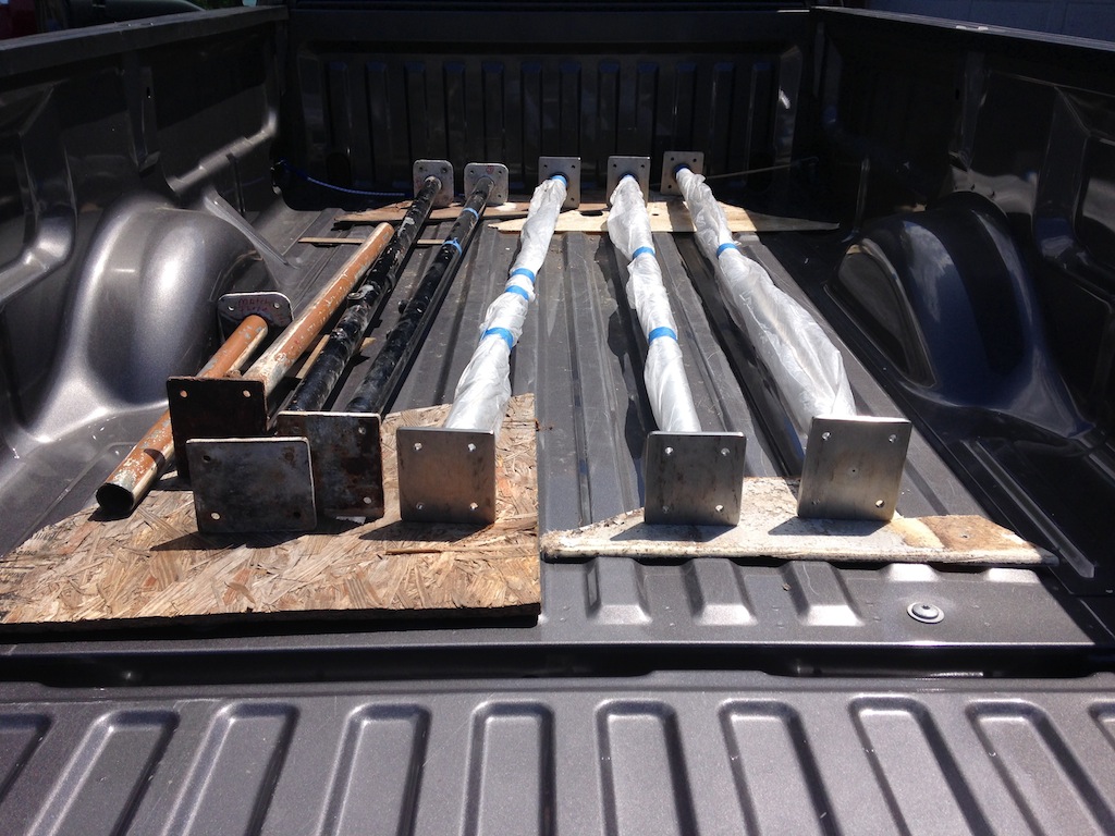
Compression posts–new and old
Highly polished stainless steel, with a mirror-like finish, would have been about twice the cost of the duller (but shiny enough) finish on the new posts. Apparently, the surface of the new posts is “180-grit” smooth.