7/6/14: Tanks, Compression Block
The baffles for the forward tank were cut from marine plywood, and were glassed on both sides.
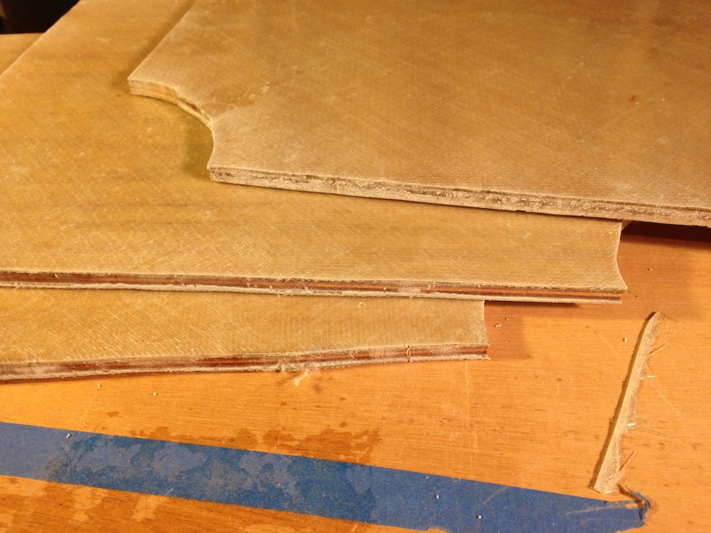
Baffles, glassed and ready for sanding
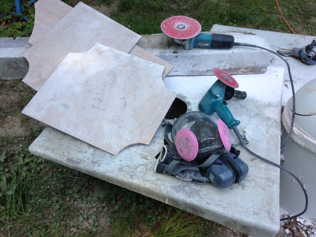
Sanded baffles, ready for installation
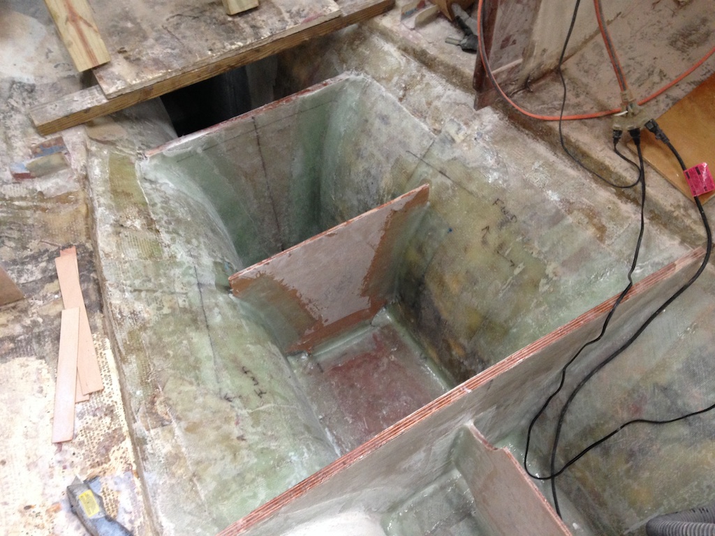
The baffles were fit into the tank, then a fillet of thickened epoxy was created along all edges that terminate on the hull, a bulkhead, or another baffle. Two layers of tabbing were then applied, creating an extremely strong structure.
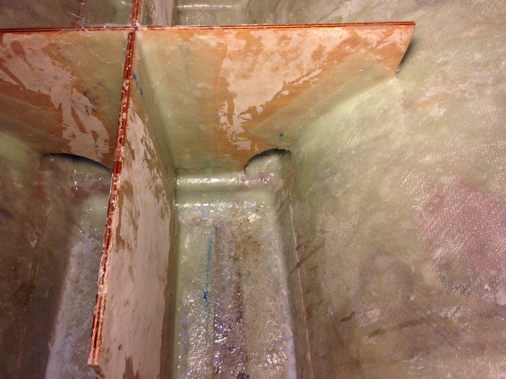
Baffles in the forward tank
Meanwhile, a sheet of 1/8″ thick neoprene gasket material was used to begin making custom gaskets for the two tank lids. The material cuts easily with a razor-knife, but careful measurements must be made prior to cutting.
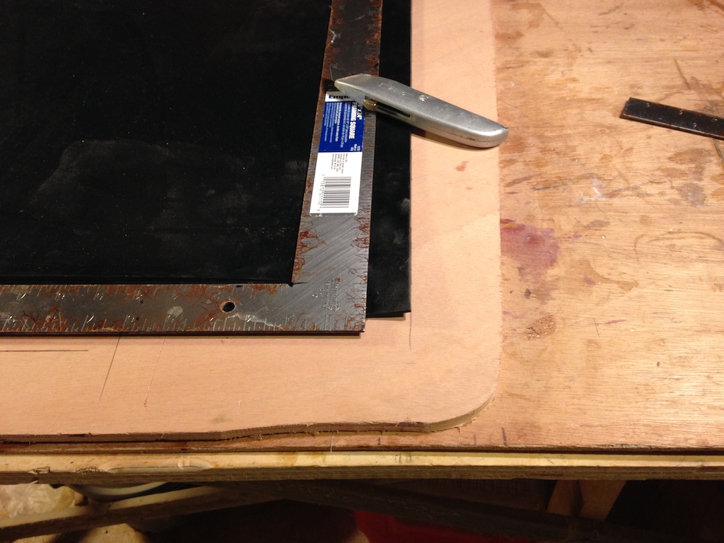
Neoprene gasket material
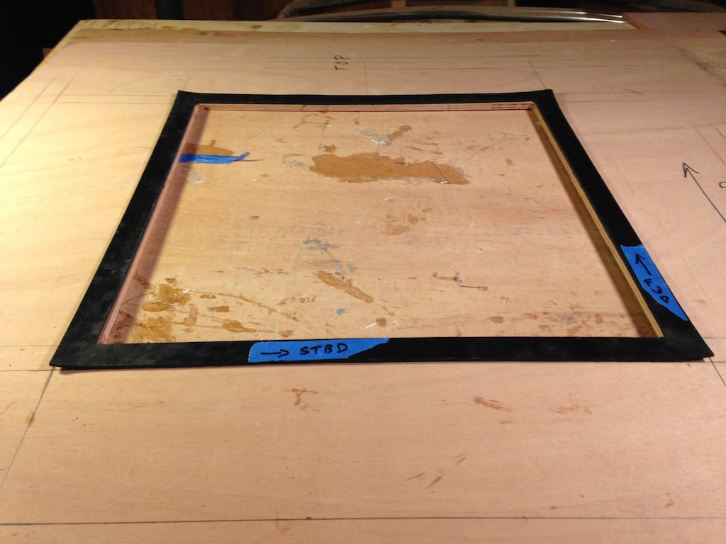
The gasket for the lid of the forward tank
Fiberglass was applied to both sides of the tank tops and lids.
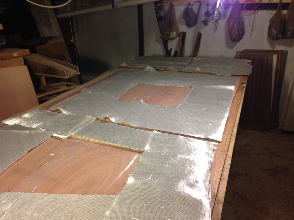
Fiberglass cloth was applied to the inside and outside surfaces.
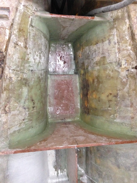
Work on the aft tank continued with the application of two more layers of tabbing to the bulkheads that define the forward and aft sides of the tank. Thickened epoxy was used to smooth the bottoms of the tank.
The aft tank area
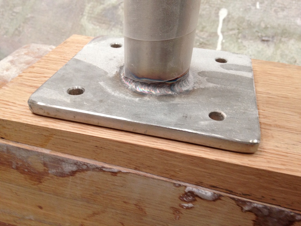
While the various fiberglass jobs dried, work continued on the compression posts and compression block. The gap between the base of the forward post and the compression block is not uniform. The gap is about 3/4″ at the forward end, but is 6 millimeters wider at the aft end. Thus, the gap cannot be filled with a rectangular piece of oak.
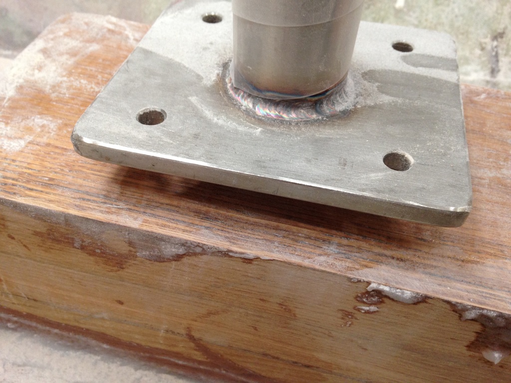
The gap between the forward compression post and the compression block
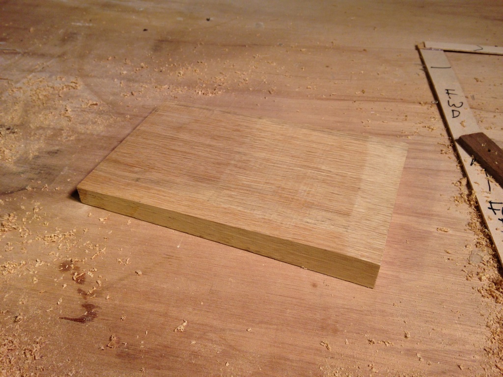
The filler for this gap started as a 6″ x 8″ x 2″ block of white oak.
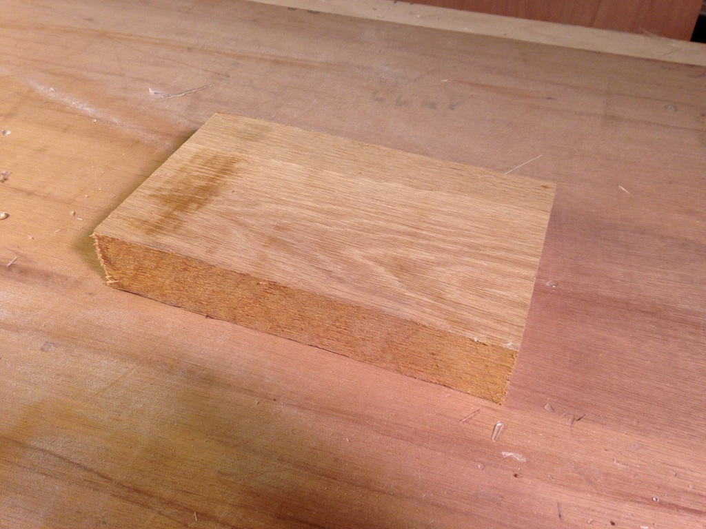
The piece of oak to be shaped
Work started by tracing the shape on the side of the block, then planing down to the thickness of the thicker end. Removing so much material requires many passes through the thickness planer, lowering the planing head only a tiny bit after each pass.
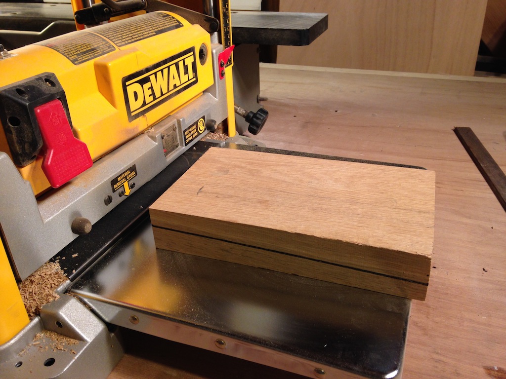
The thickness planer
Planed to the thickness of the thicker end
“In metalworking and woodworking, a jig is a custom-made tool used to control the location and/or motion of another tool.” A crude jig was constructed whose purpose was to raise one end of the block 6 millimeters higher than the other. The block was then run across the jointer until the correct bevel spanned the length of the block.
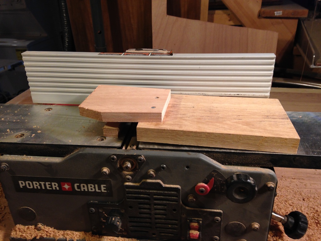
A simple jig
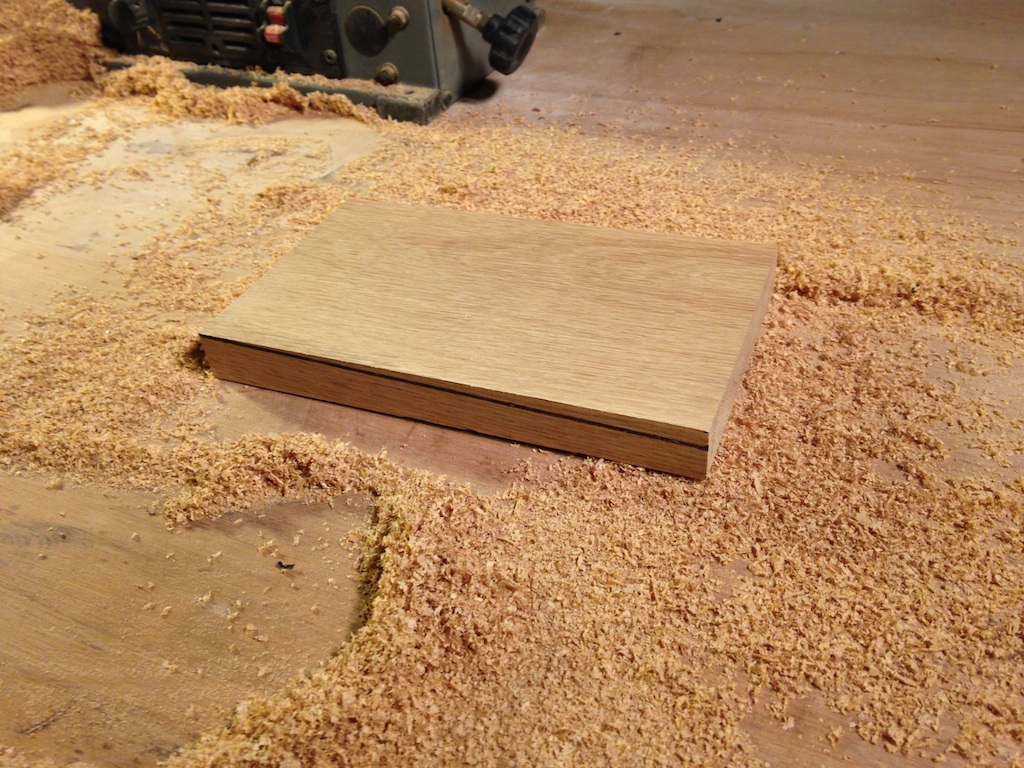
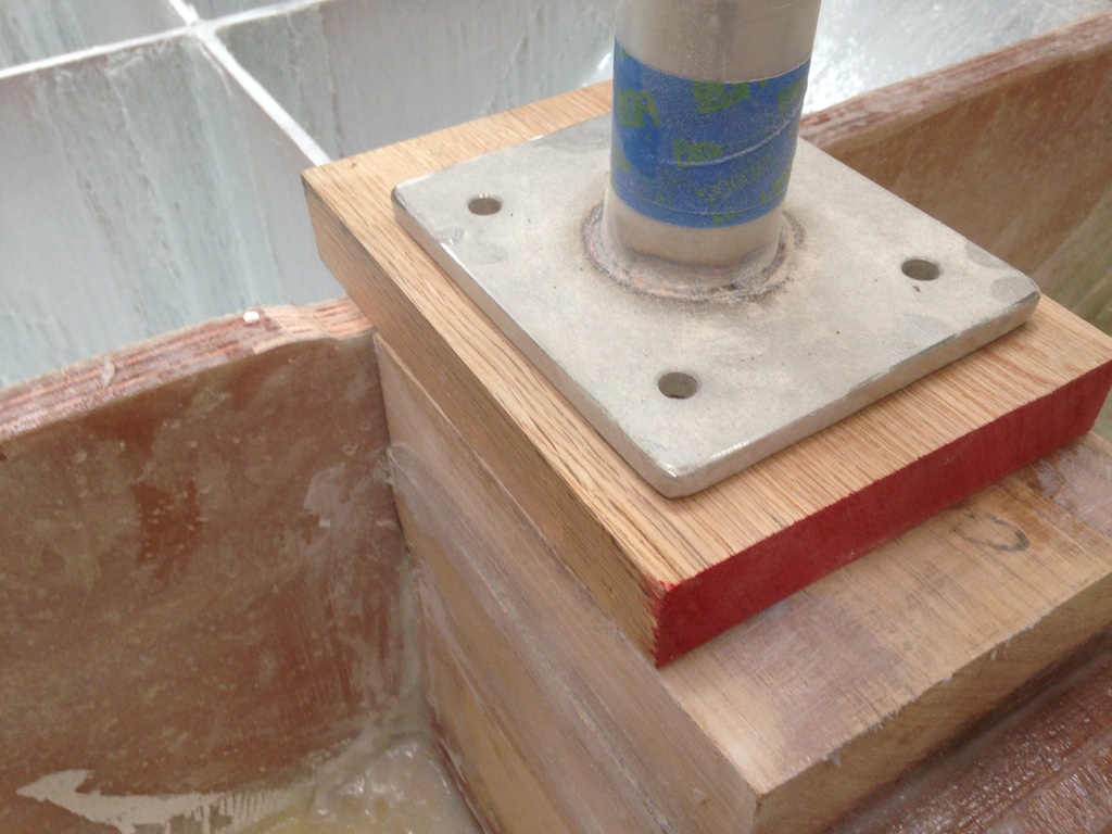
The completed wedge-shaped block
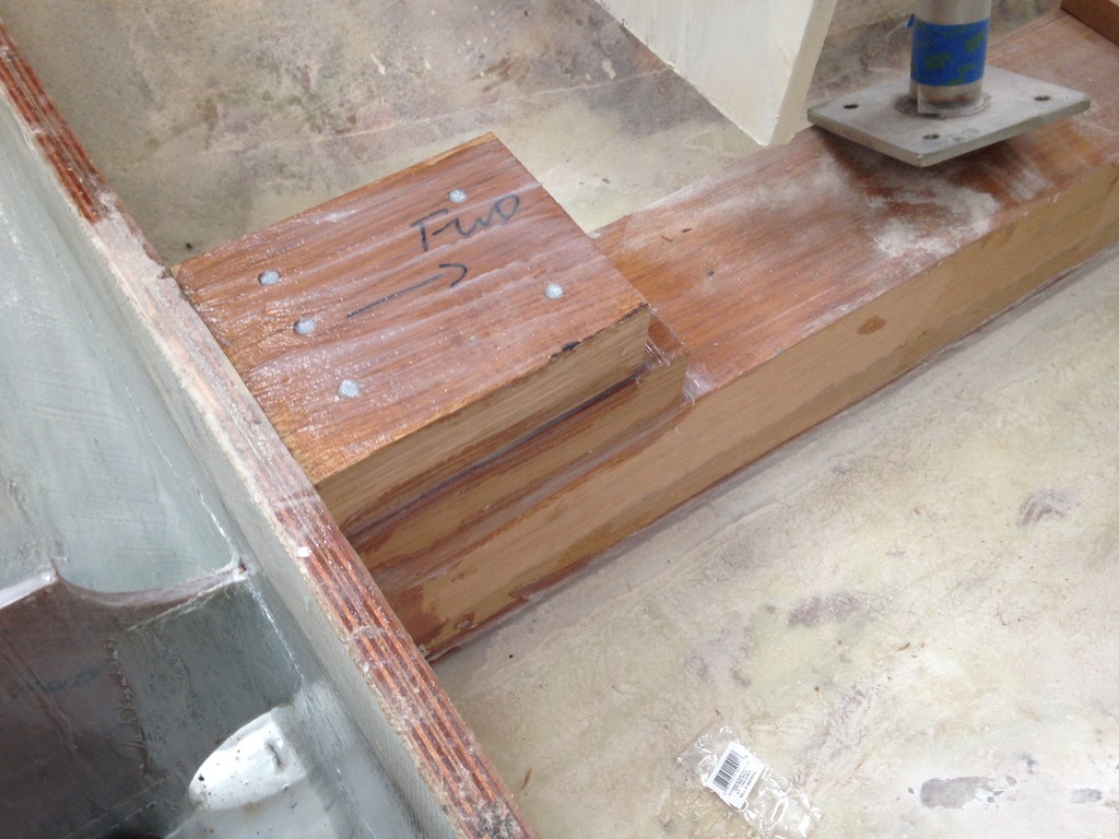
Finally, the wedge-shaped block was test fitted, as shown in the following photo.
Test fitting the wedge
The compression post that sits on the aft end of the compression block is shorter than the forward post, so the compression block was build up at the aft end with additional blocks of oak. Clamping these blocks would have been difficult, so they were, instead, screwed down after being set in thickened epoxy.
Building up the aft end of the compression block
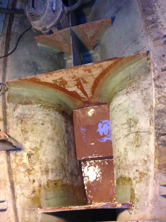
Once again, the gap between the top of the compression block and the base of the aft post was not uniform, so a wedge-shaped filler block was built. The result is show below. Work will continue by aligning the posts, then bolting them to the compression block.
The filler block at the aft end of the compression block
Work resumed on the aft tank, where a layer of fiberglass was applied to the bottom and sides, and a layer of tabbing was applied along all seams.
The aft tank area with fiberglass on the bottom, sides, and along the seams
One objective of the additional glass and tabbing is to create an impenetrable barrier between the tank contents and the hull. Only the two curved sides of the tank lie against the hull, and currently there is one layer of 17-oz biaxial fiberglass applied to that area in the aft tank. Is this enough? This fiberglass (which was wetted out with a West System 105/206 mix) will be followed by three+ coats of brushed on epoxy. This should be sufficient. To be sure, however, an inquiry was made with West System’s technical staff, and here is their reply, in which they comment on the state of the forward tank:
“I think you have it well under control. With the 2 layers of 17 oz. biaxial you have about .085” plus the 3 additional fill coats that add ~.012”, so nominally .097”. We recommend a minimum film thickness of .020” to barrier coat the outside of the hull, so you’re well above that.”
Based on their reply, then, even one layer of 17-oz biaxial against the hull in the aft tank is more than sufficient.
The aft tank is narrower than the forward tank, but deeper, and baffles will divide it into three compartments. The following photo shows the pattern that was used for the athwartship baffle.
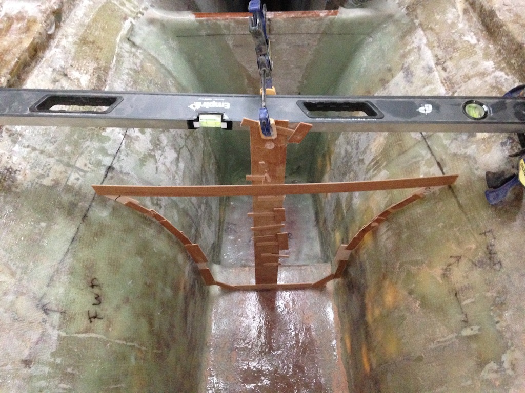
The pattern for the athwartship baffle in the aft tank
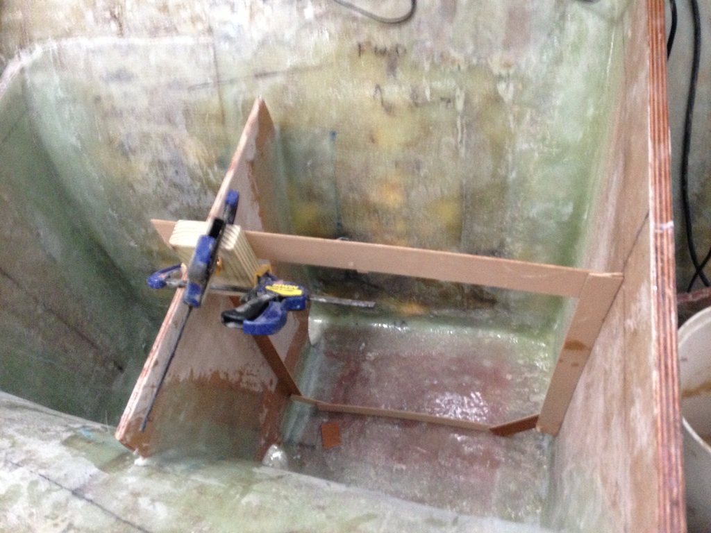
Using the pattern, the shape is transferred to marine plywood.
A good fit
Next, the baffle was glassed on both sides. When the glass was dry, the baffle was washed, then sanded, then tabbed into place. (Newly cured epoxy is always washed because a waxy substance called “amine blush” may form during an epoxy cure. The amine blush can interfere with the adhesion of additional coatings. Amine blush is water soluble and may be removed with a simple water wash.)
The athwartship baffle, tabbed into place
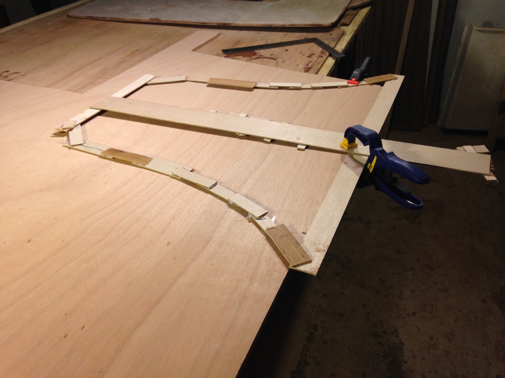
Next, a pattern was made for the fore/aft baffle.
The simple pattern for the fore/aft baffle
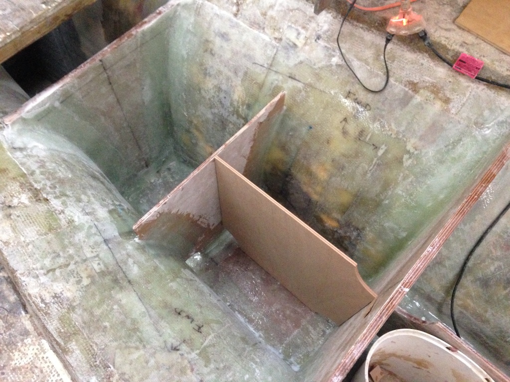
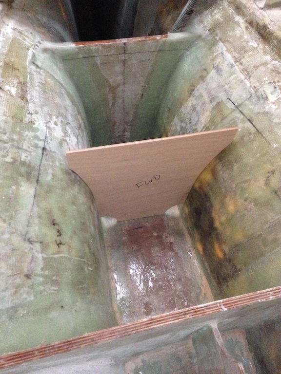
The fore/aft baffle
This baffle was tabbed into place. Both tanks were then prepared for 3+ final coats of epoxy mixed with a white pigment. The white color will not only make cleaning easier, but it will make issues (should they arise) easier to identify. The following photo shows the two tanks after one coat of the white epoxy has been applied.
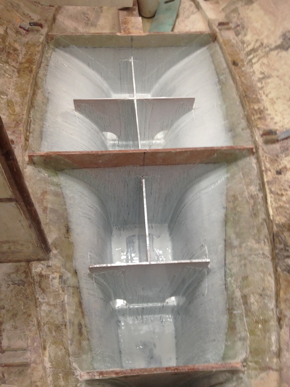
After one coat of white epoxy