7/29/14: Tanks, Compression Posts
The tops of the tanks have been tabbed in place with one layer of tabbing applied along the inside edge. Next, the gaps around the perimeter of the tank tops were filled and faired. Tabbing was then applied to the tops of the tanks, followed by more fairing.
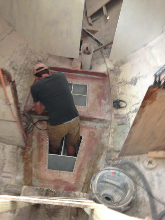
Filling and fairing the gap between the tank tops and the hull
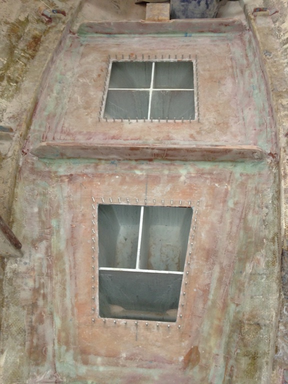
Here the tops of the tanks are ready for a coat of primer.
Construction of the aft tank precluded painting and priming the forward end of the bilge.
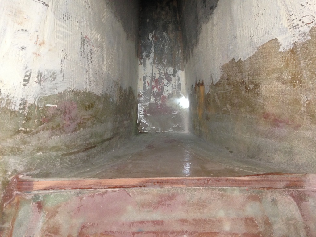
Looking down into the bilge
In the previous photo, you can see sunlight shining through the garboard drain hole at the bottom of the bilge. This hole is partially blocked with fiberglass tape, and the following two photos show that the hole was cleaned up from the outside of the boat.
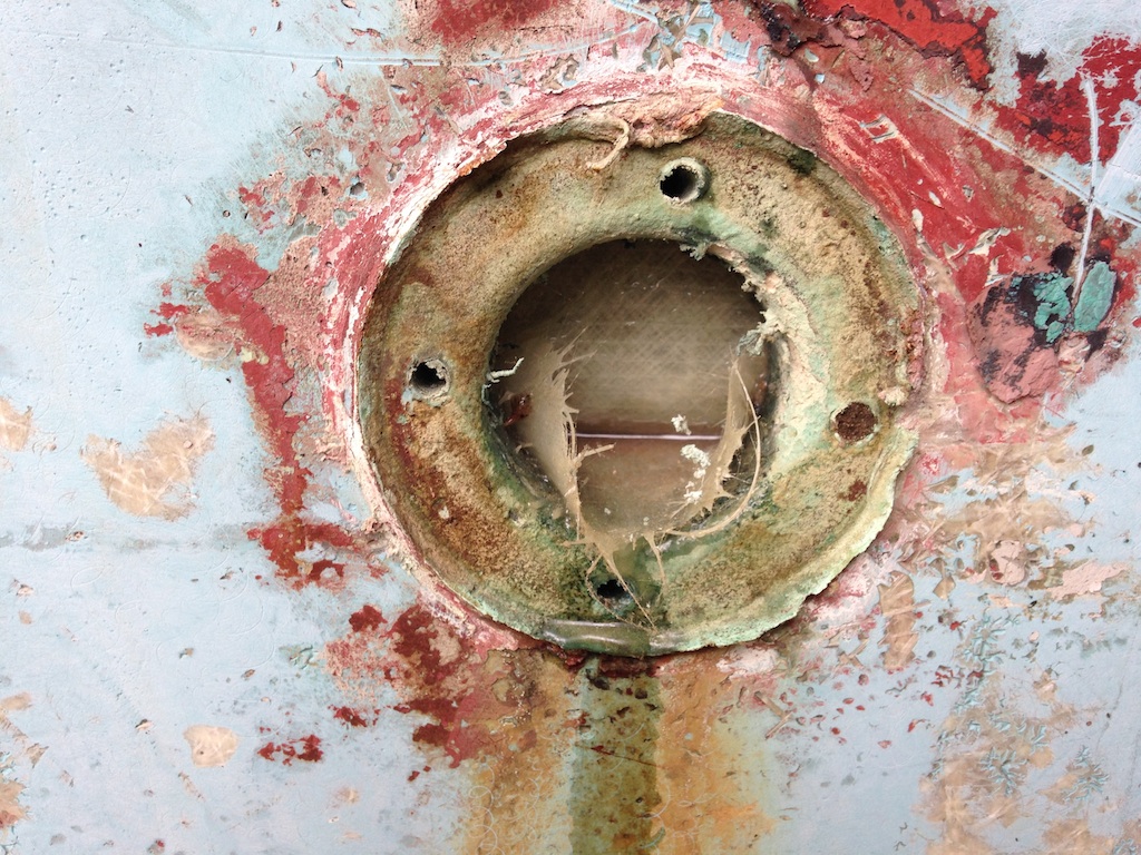
The garboard drain hole: blocked
In the following photo we can see that the level of the bottom of the bilge is even with the bottom of the garboard drain hole.
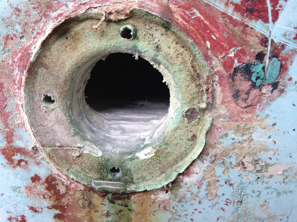
The garboard drain hole: cleaned up
The bottom of the bilge is a long reach, so a paintbrush was taped to the end of some scrap wood.
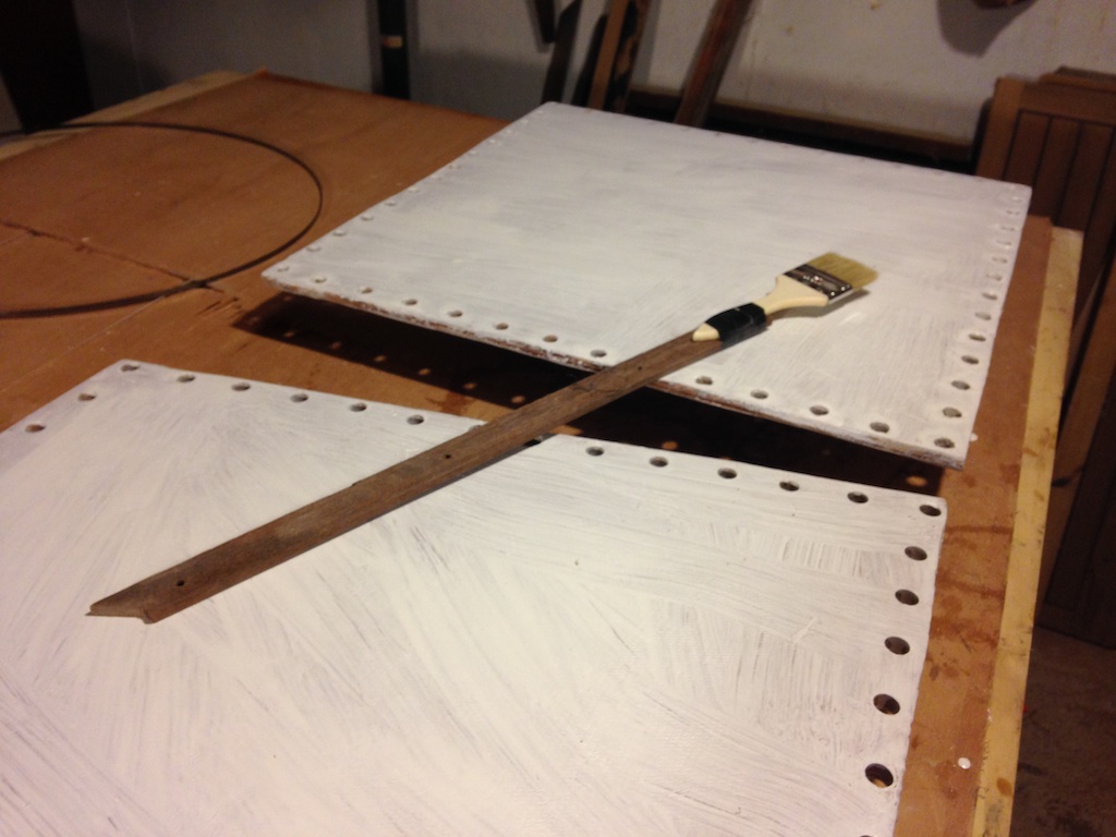
A high-tech tool for painting the bottom of the bilge
The following photo shows the situation after one coat of primer was applied. Note, again, the sunlight shining through the garboard drain hole.
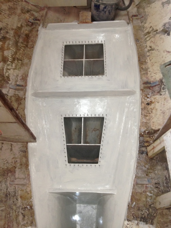
After priming
Next, two coats of gray Bilgekote paint were applied.
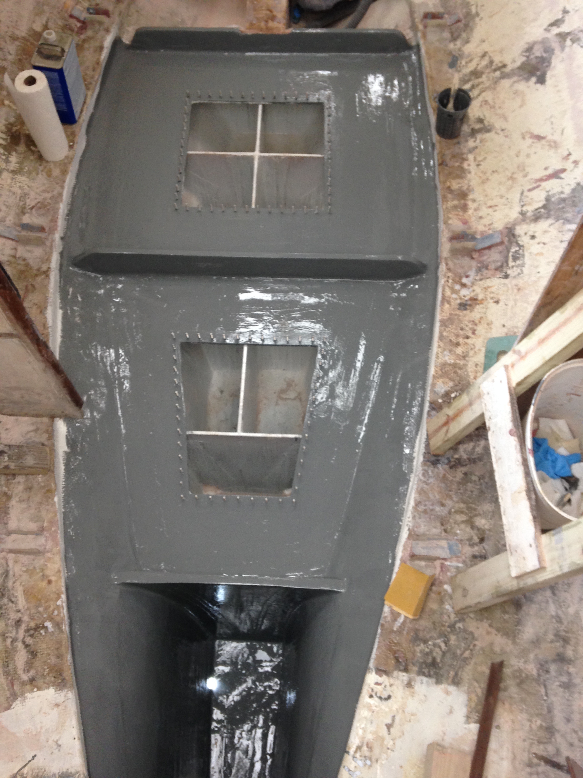
Two coats of gray Bilgekote
The capacities of the tanks must be measured and then the tanks must be pressure-tested. Fittings for the tank vents were installed, which will be used in the pressure tests. These fittings are one-inch Marelon though-hull fittings. Here they have been bonded permanently with epoxy thickened with high-density filler.
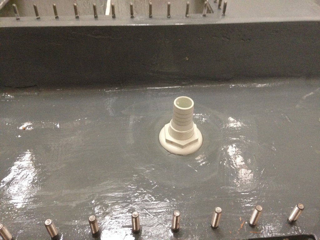
Vent fitting on the aft tank
The capacities of the tanks were measured by the timing method used previously to measure the capacities of the old tanks. See Tank Discussion for a review of that work. Recall that the capacity of the old forward tank is 34 gal, while the capacity of the old aft tank is 55 gal. The measurements showed that the new forward tank has a capacity of 70 gal, while the new aft tank has a capacity of 75 gal. The forward tank will be the holding tank, while the aft tank will be the fresh water tank.
Measuring the capacity of the aft tank
Pressure testing tanks serves the dual purpose of testing the strength of the tanks and testing for leaks. Pressure testing a tank using air can be dangerous because air is very compressible. If the tank were to fail, the sudden release of compressed air could be like an explosion. These new tanks were pressure tested using water. The following photo shows the tanks filled with water. Note the the custom-made gaskets have been installed.
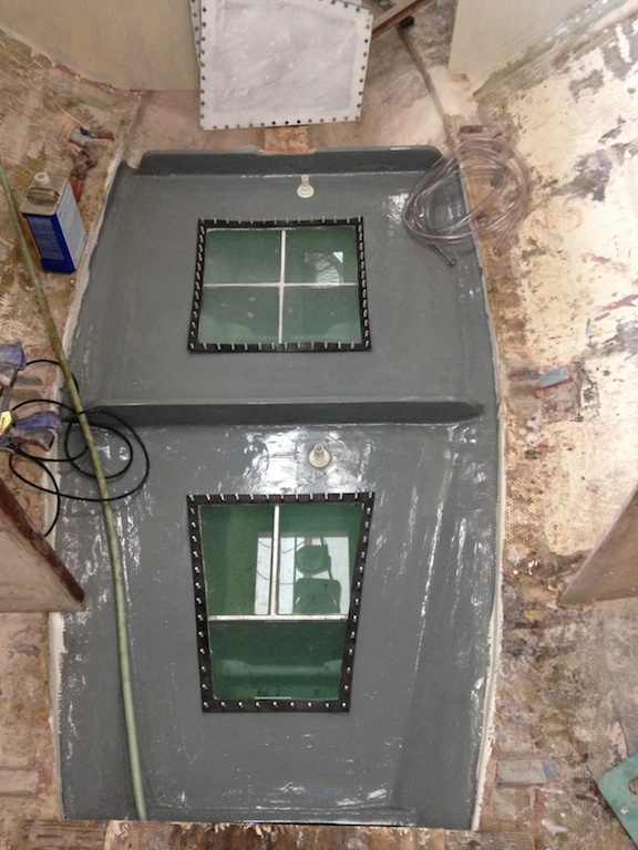
Tanks filled, awaiting pressure testing
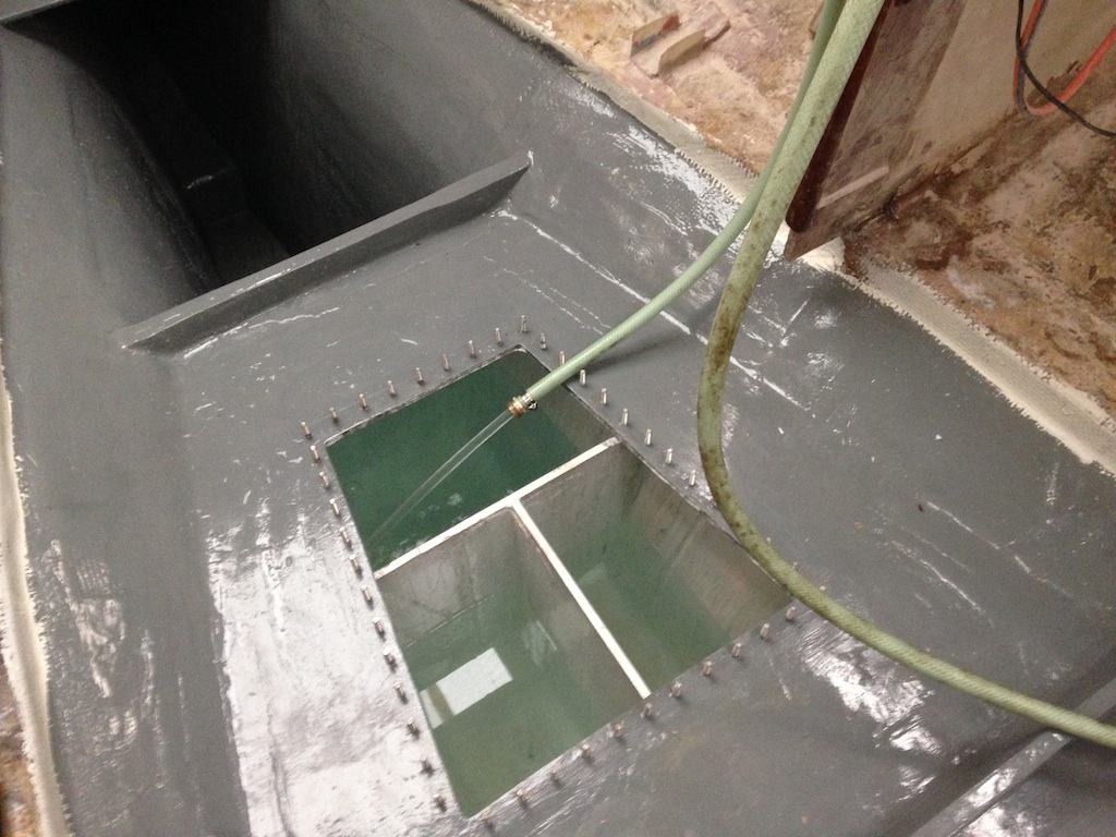
With the tank lids installed, a clear hose was connected to a vent fitting, then the hose was led upward and through the main cabin hatch. The level of the water in the hose determines the additional pressure in the tank. By some standards, a pressure approaching 3 psi (pounds per square inch) should be applied, then maintained for an unspecified amount of time. The top of the forward tank measures about 42″ by 40″, so an upward force of 42 x 40 x 3 = 5040 lbs is generated by the application of 3 psi.
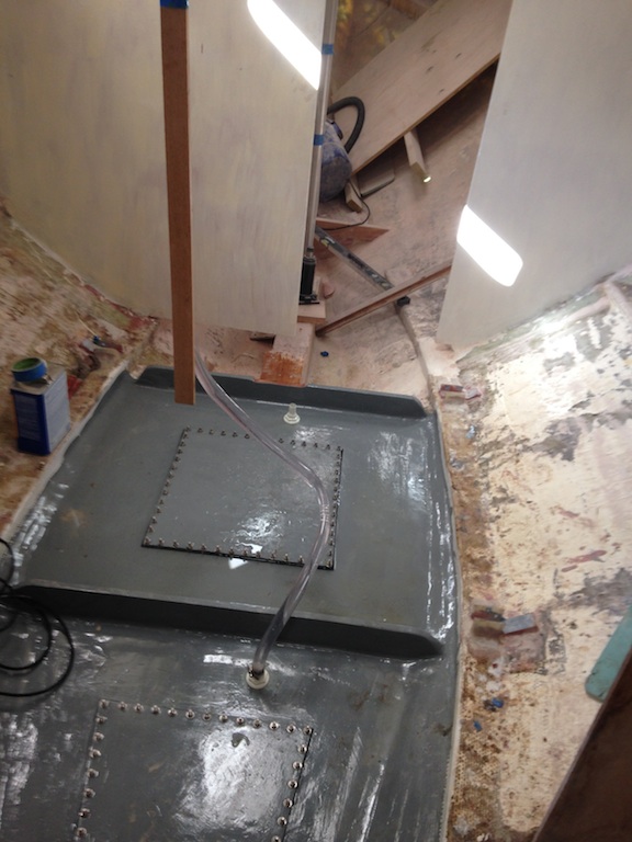
The height of the static water determines the pressure in the tank.
To achieve a pressure of 3 psi, the clear hose must be filled with water to a vertical height of about 7 ft above the vent fitting. Each tank was tested in this way by filling the hose with water, little by little, until the desired height was reached. There were a few creaks during each test, as expected, but there were no leaks or mechanical failures. The tops of the tanks, in fact, experienced no distortion that was visible to the eye. Once maximum pressure was reached, the level of the water in the hose was marked, as shown below.
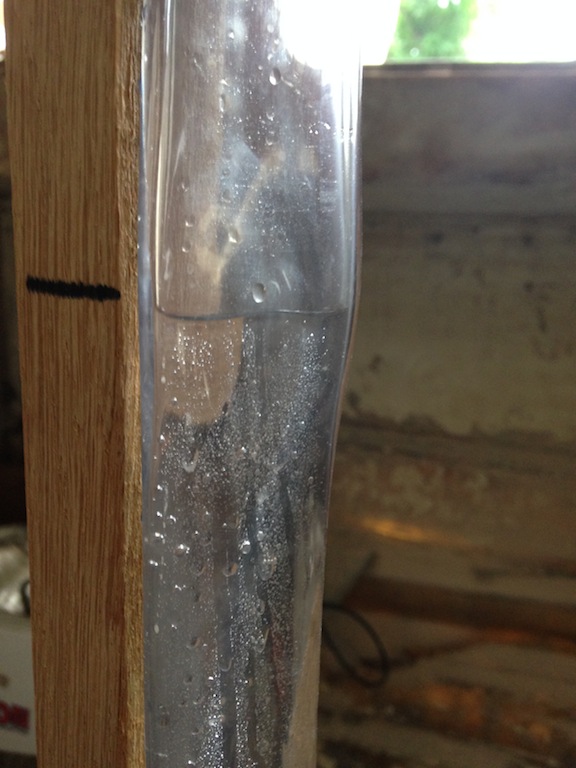
Marking the water level in the hose
The water level initially dropped very slowly, but eventually (after some hours) held steady. This was expected as the tops, hull, and bulkheads that make up the tank will flex slightly under pressure. The baffles, which are wood cored, would be expected to compress slightly under pressure. The expansion and contraction of the water and the tanks with changing temperature is another factor that can effect the level of the water in the clear hose. The conclusion is that the tanks are mechanically sound and leak free.
Meanwhile, work continued on the compression posts and compression block. Recall that wedge shaped pieces of oak were fabricated to fill the space between the plates at the bottoms of the compression posts and the top of the compression block. These horizontal plates are nearly flush with the compression block (at the bottom ends) and the coachroof (at the top ends), but not perfectly flush. If the plates are not flush, then they will experience some torque when the posts are under compression. To eliminate this possibility, epoxy thickened with high-density filler was used to fill whatever small gaps remained. After bedding the top plates in thickened epoxy, then bolting the top plates to the coachroof, the celling was jacked up slightly (perhaps 1/4 inch) to increase the gap at the bottom plates, which allowed thickened epoxy to be injected before lowering the jack.
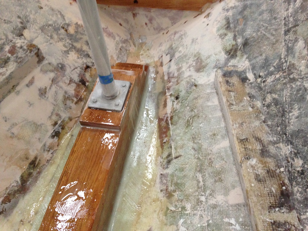
Lag bolts connect the bottom plates to the compression block, and the following photo shows the situation just before the lag bolts were tightened.
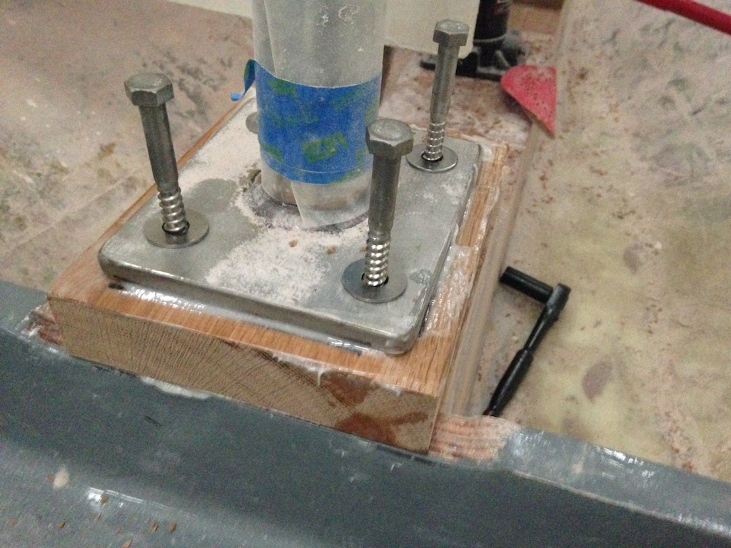
The bottom of the aft compression post
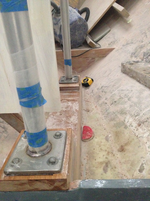
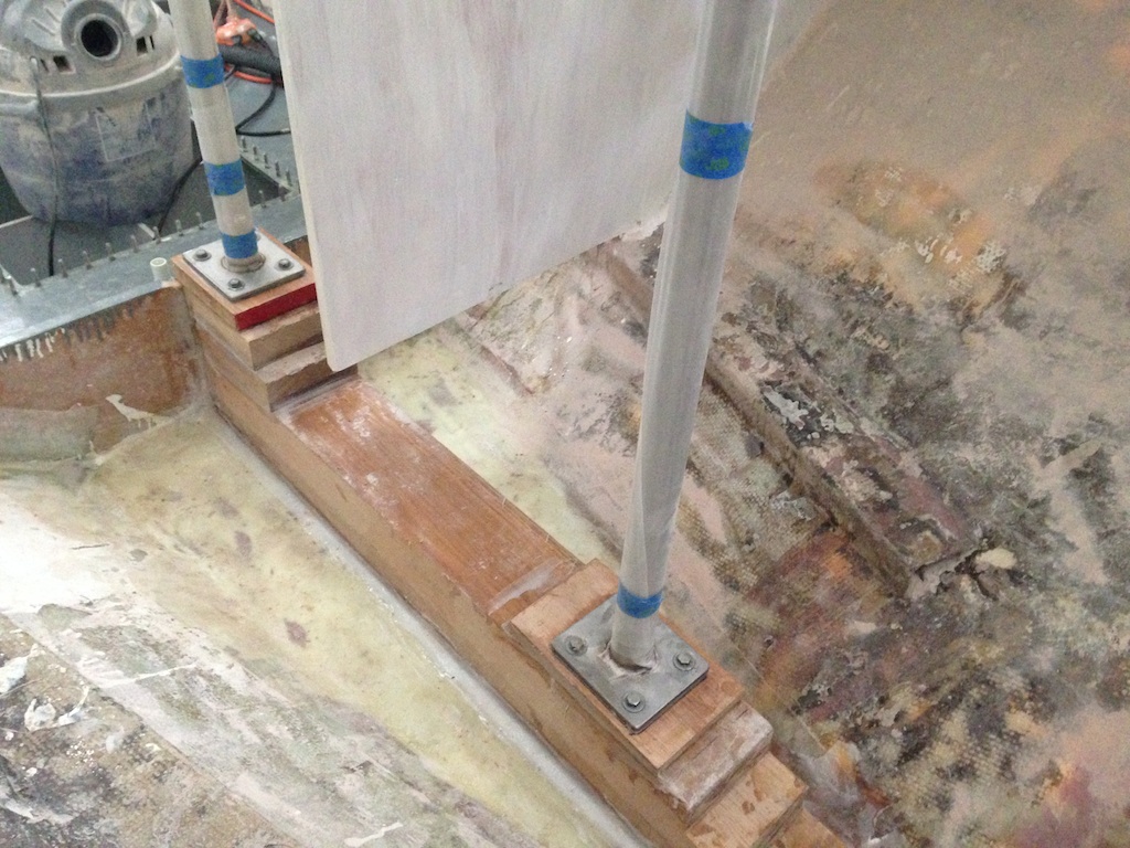
The following two photos show the situation just after the lag bolts were tightened. Bedded in epoxy in this way, the compression posts are now essentially permanent.
The space around the compression block is under the forward part of the salon and the head space. It will be primed and painted, like the other bilge areas, but first the compression block was sealed with epoxy and then fiberglass tabbing was applied along the bottom edge.
Sealed with epoxy and tabbed at the bottom edge
Once of the bilge areas are painted, work will continue on building the floor timbers.