7/4/16: Sink Area, Shelves, Compression Post, Holding Tank, Forpeak
SINK AREA
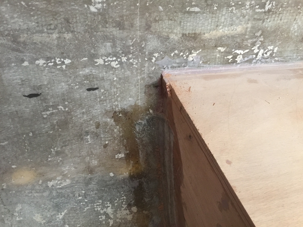
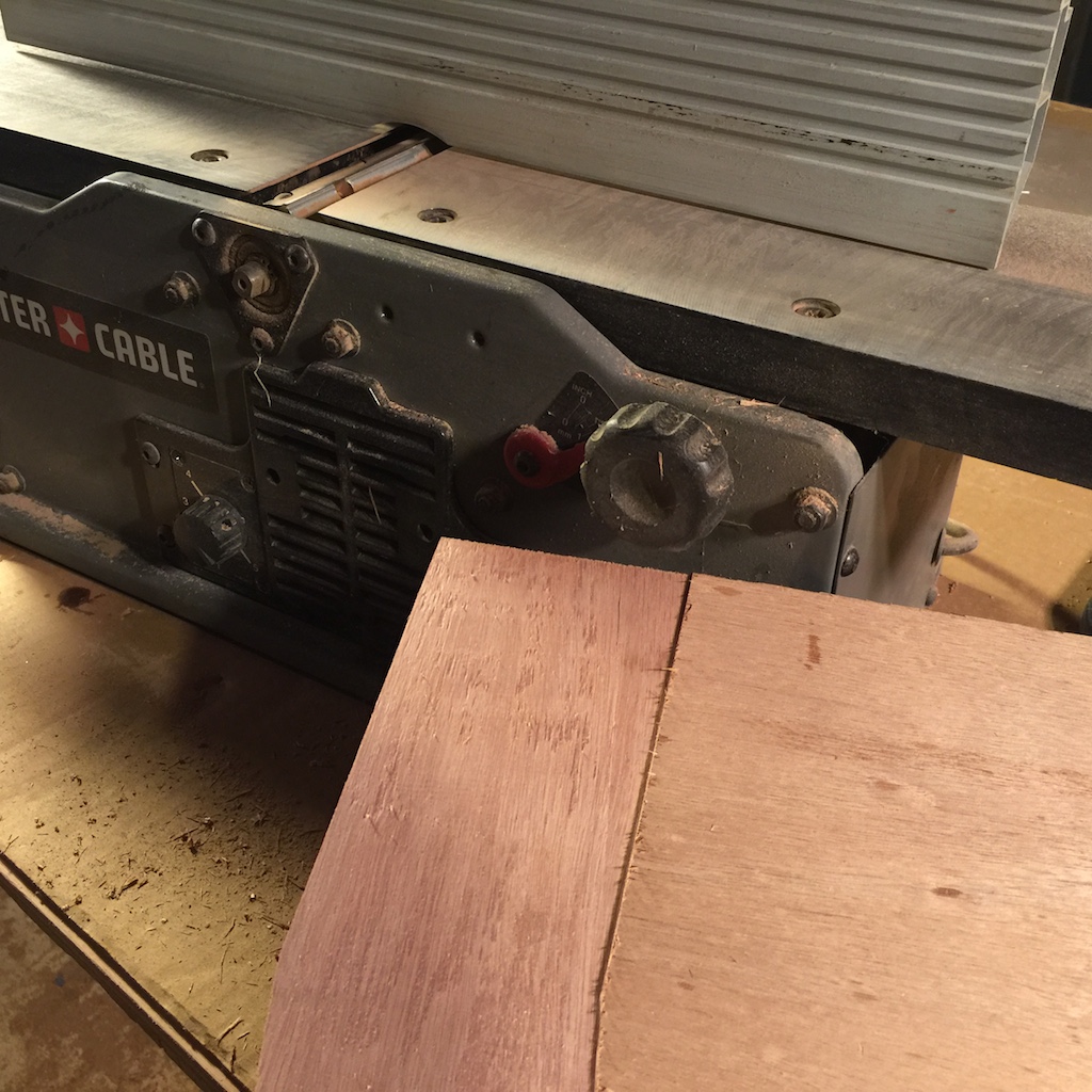
My next task was to fabricate the countertop surrounding the sink, which will be continuous with the countertop over the icebox. I started by cutting off a bit of overhang that the router couldn’t reach.
Next, I cut up some teak cleats from some scrap teak.
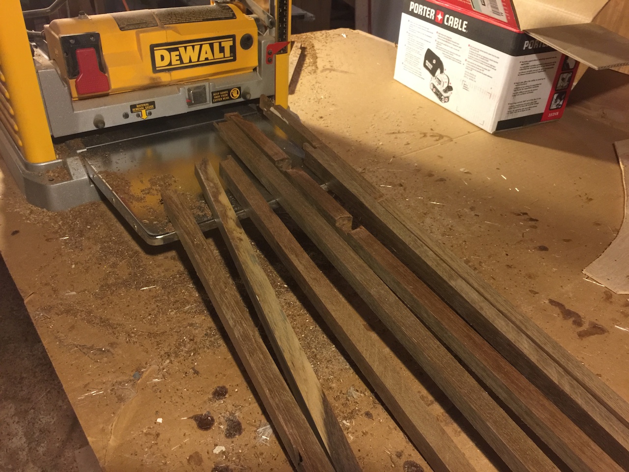
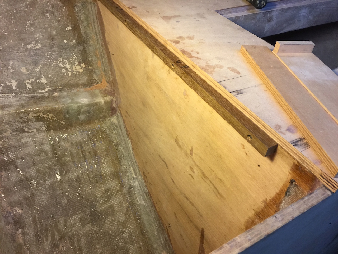
Two cleats support the fore and aft edges of the sink-area countertop, which is made of 5/8-inch plywood.
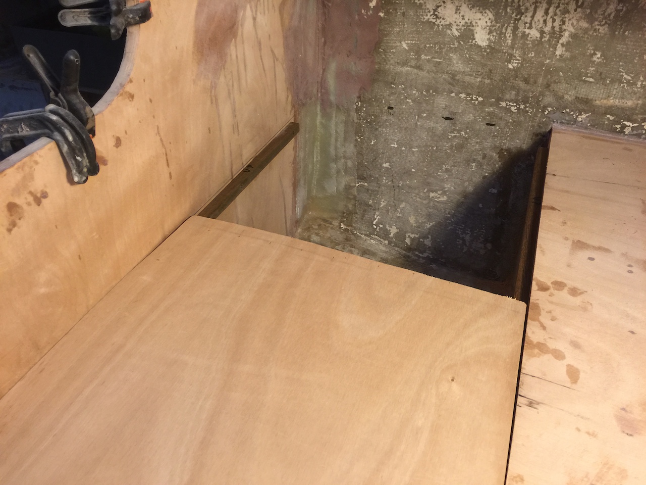
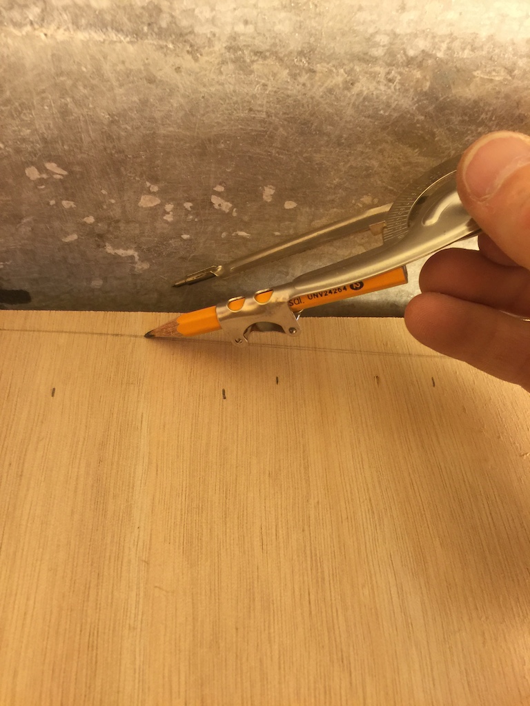
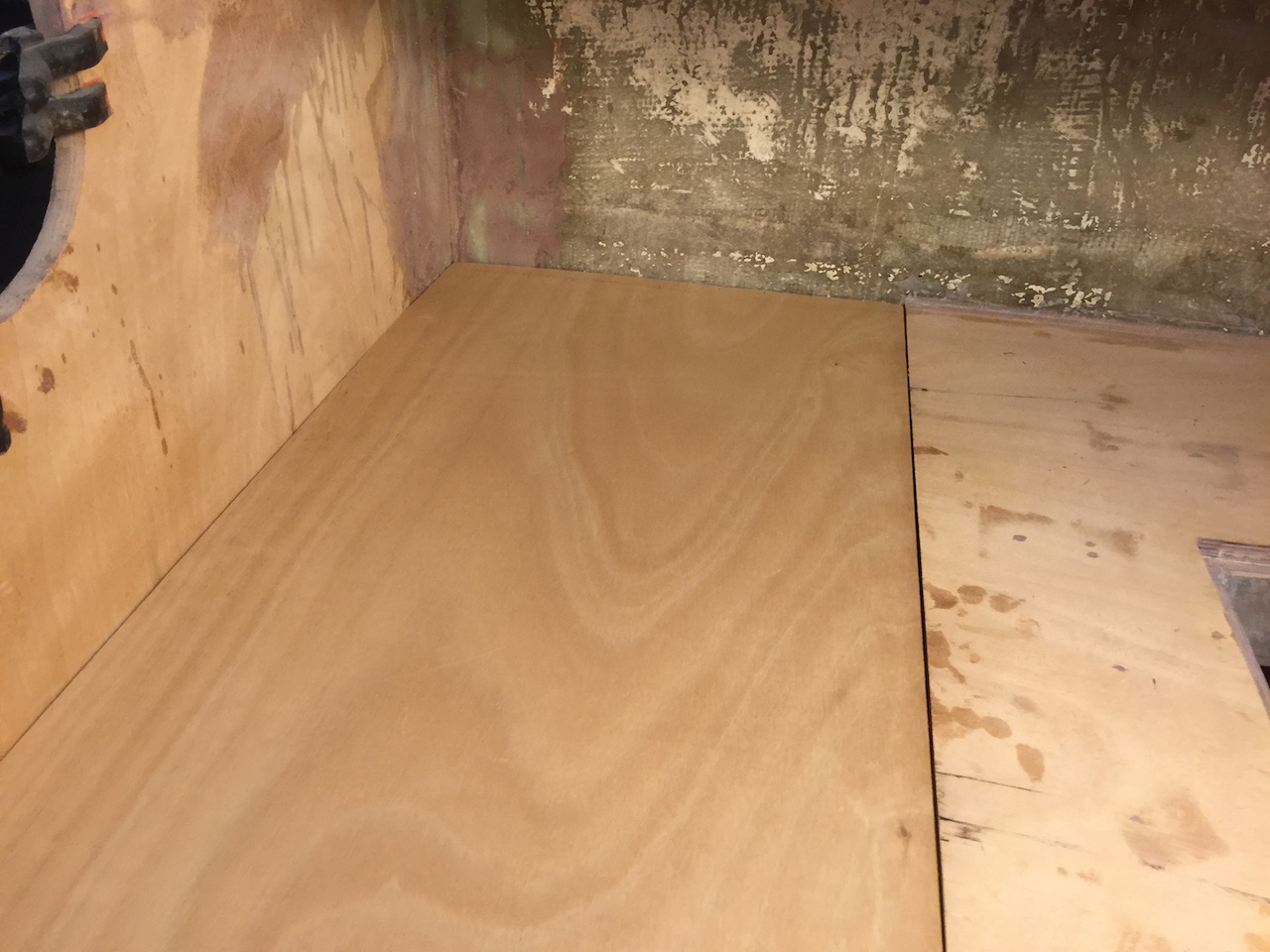
I scribed the edge along the hull to capture the shape of the hull, then cut the plywood. Small adjustments were made to accommodate the tabbing along the bulkhead, and the result was a good fit.
The gap at the merging of the two countertops will be filled to make a continuous, smooth transition. The edge along the hull will be filleted and tabbed, and the edge along the bulkhead will be filleted, but all that has to wait.
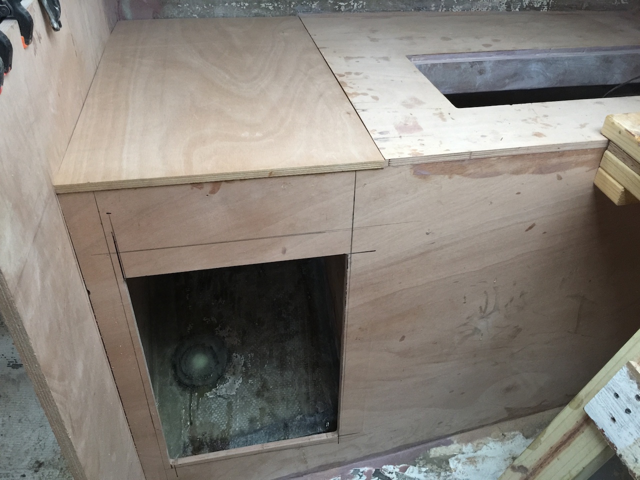
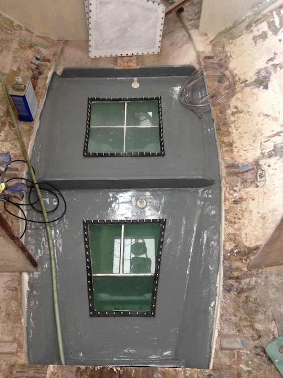
The sink will be installed toward the inboard edge, creating some dead space under the counter between the sink and the hull. One of the overriding principles of this project is that all areas must be accessible. Thus, if this dead space cannot be reached, then it must be filled or made into a top-loading storage compartment. While more storage is generally good, top-loading storage here might be impractical because it would be directly under countertop storage.
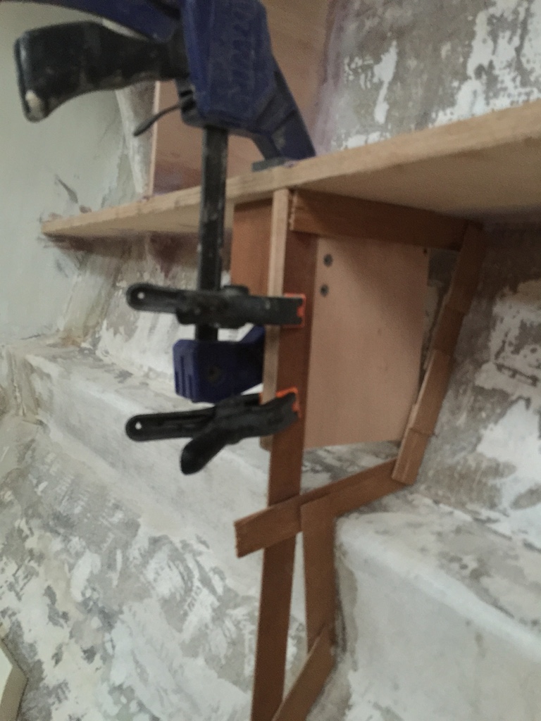
With these thoughts in mind, I decided on the dimensions of the under-sink cabinet door, and began marking and cutting.
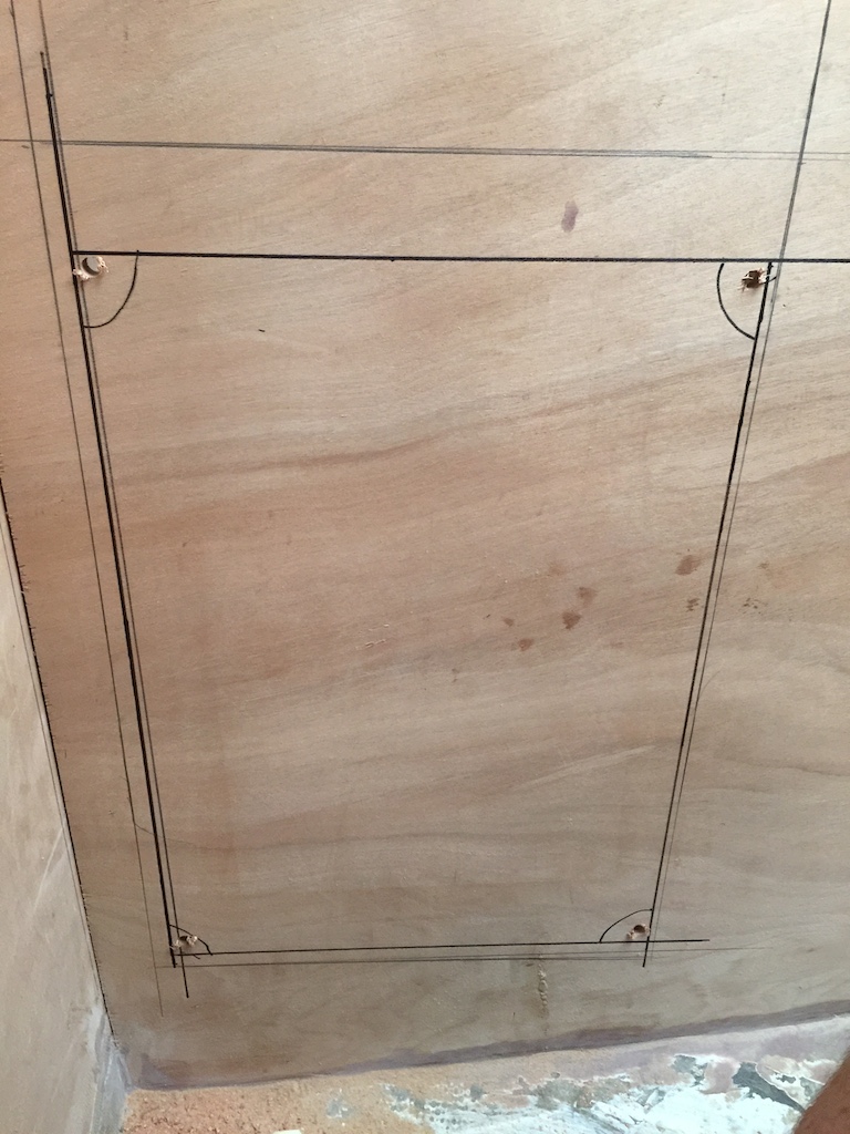
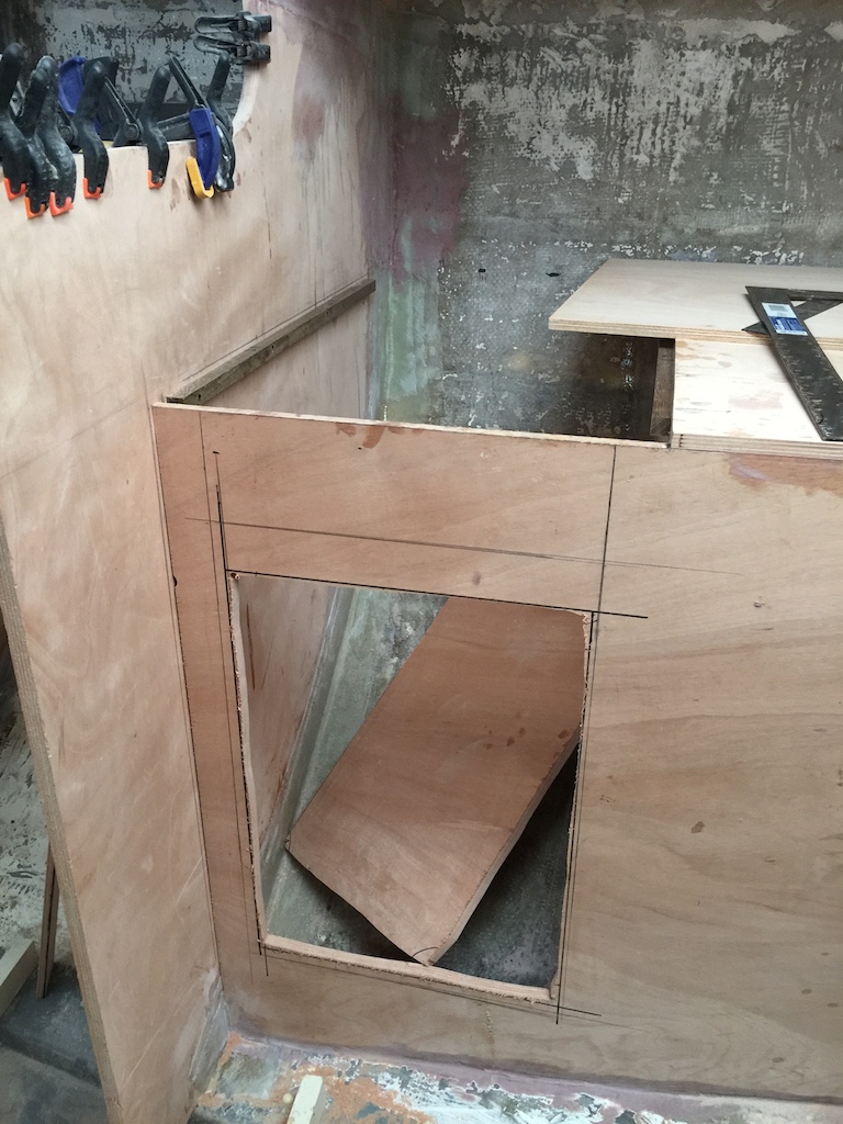
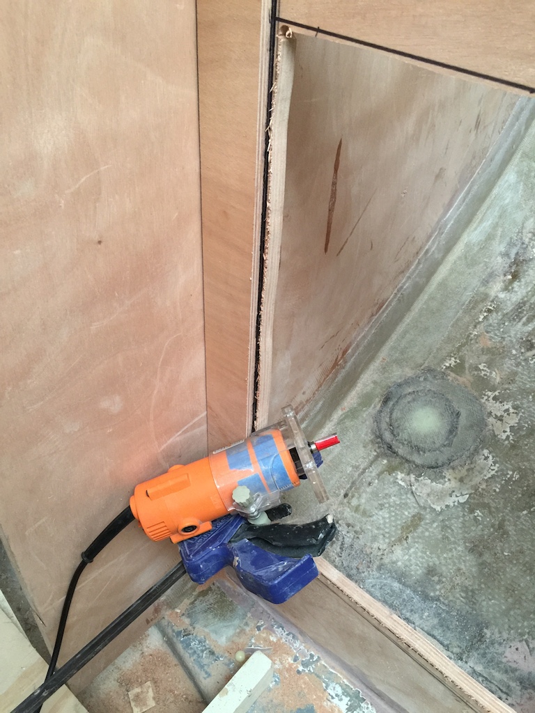
Using a straight plywood edge as a guide, the detail router was used to trim the perimeter of the opening.
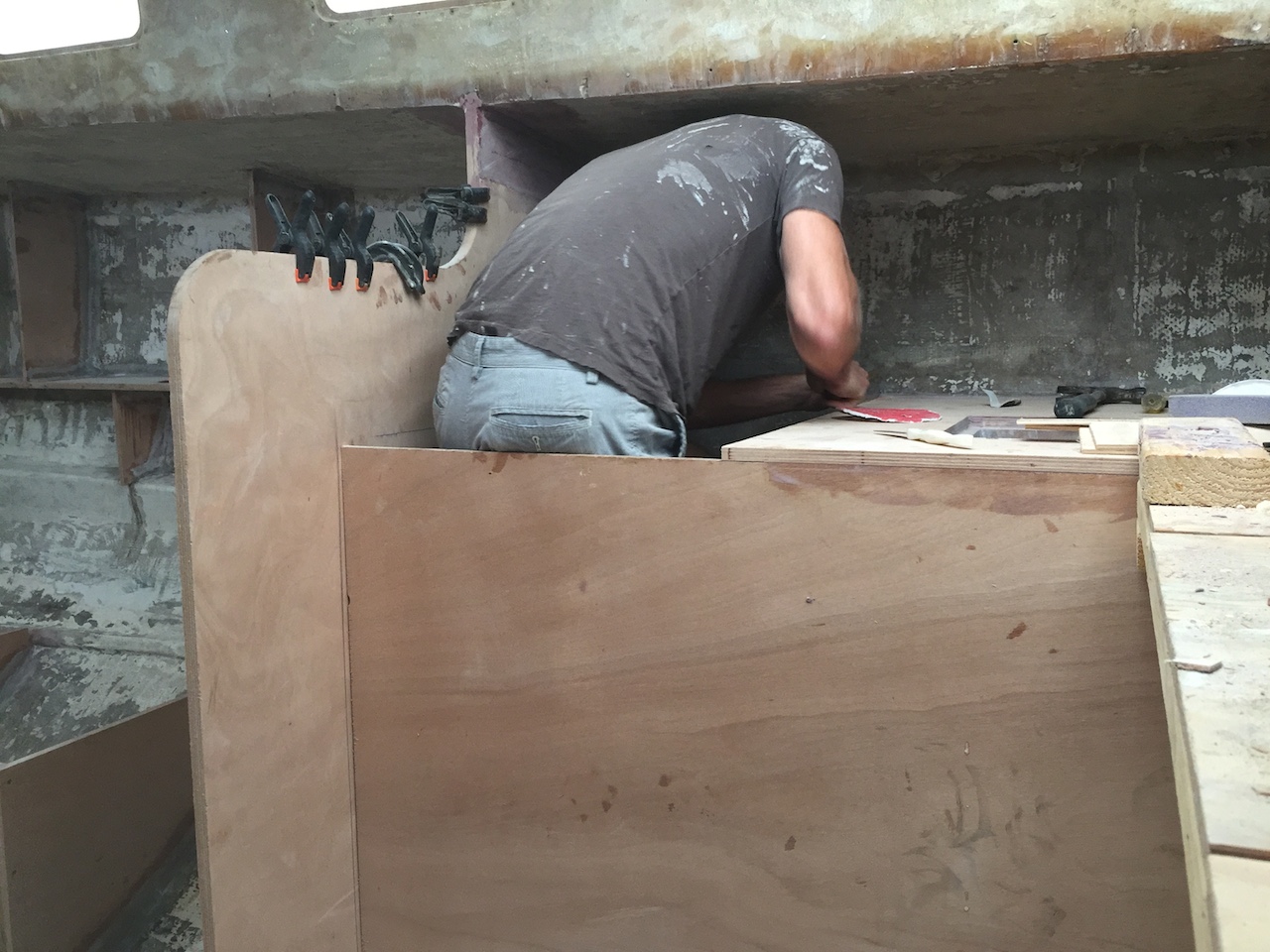
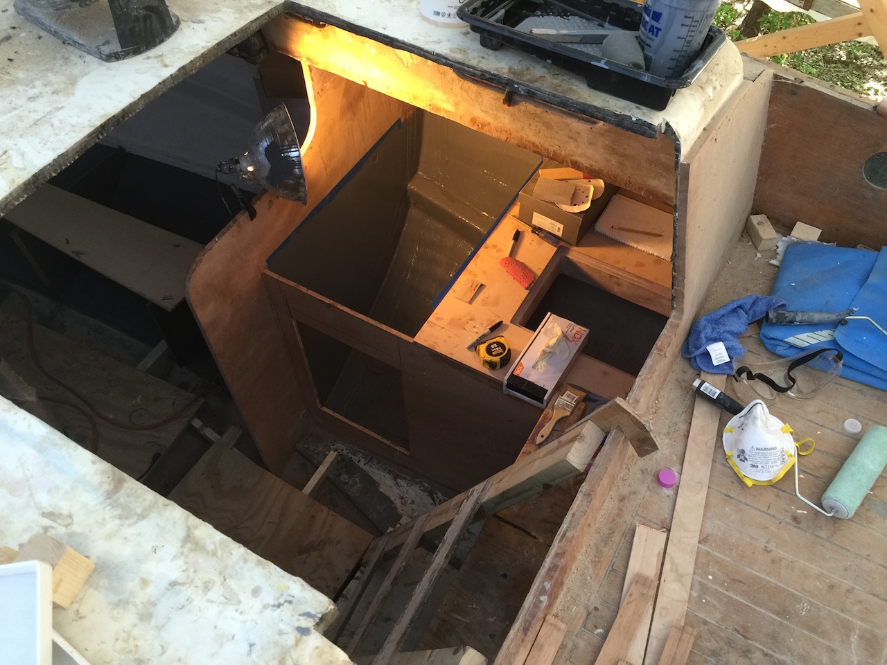
I tested accessibility by crawling into the under-sink space to my waist. The sink and plumbing will interfere somewhat, but for now I’ll proceed assuming that there will be sufficient accessibility.
In the next photo you can see the under-sink area with one coat of primer and two coats of paint.
SHELVES
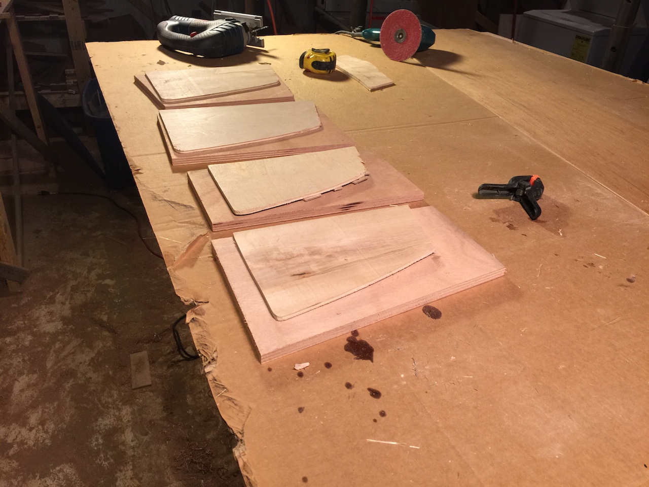
I continued to make patterns for the shelf dividers that were installed both above and below the main shelf.
These small pieces can be cut from the piles of scrap accumulating in the workshop.
I continued with the usual procedure of filleting and tabbing.
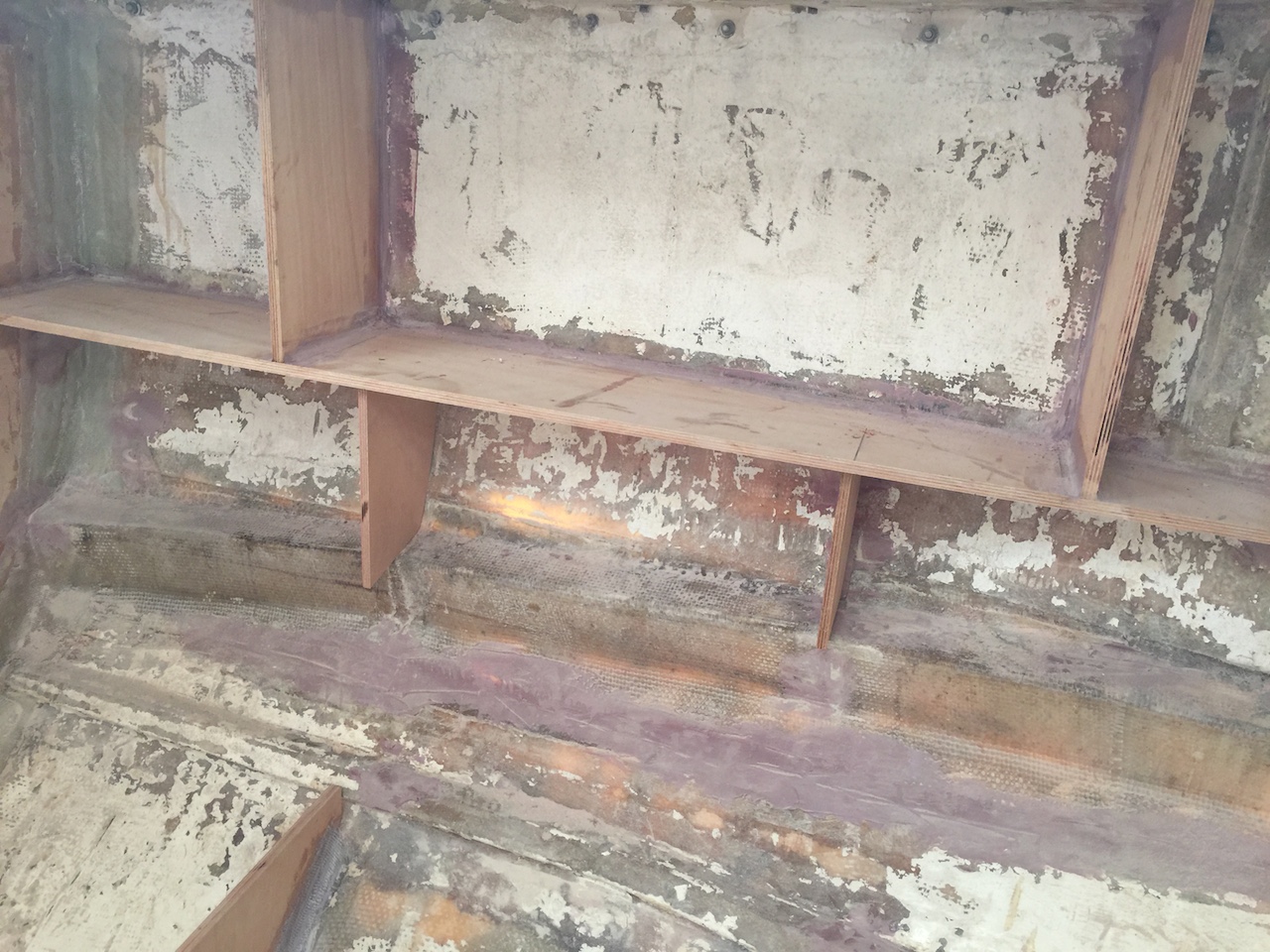
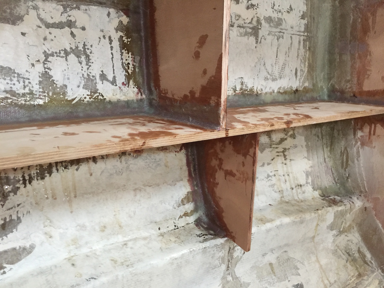
The following two photos show the port and starboard sides of the salon, respectively.
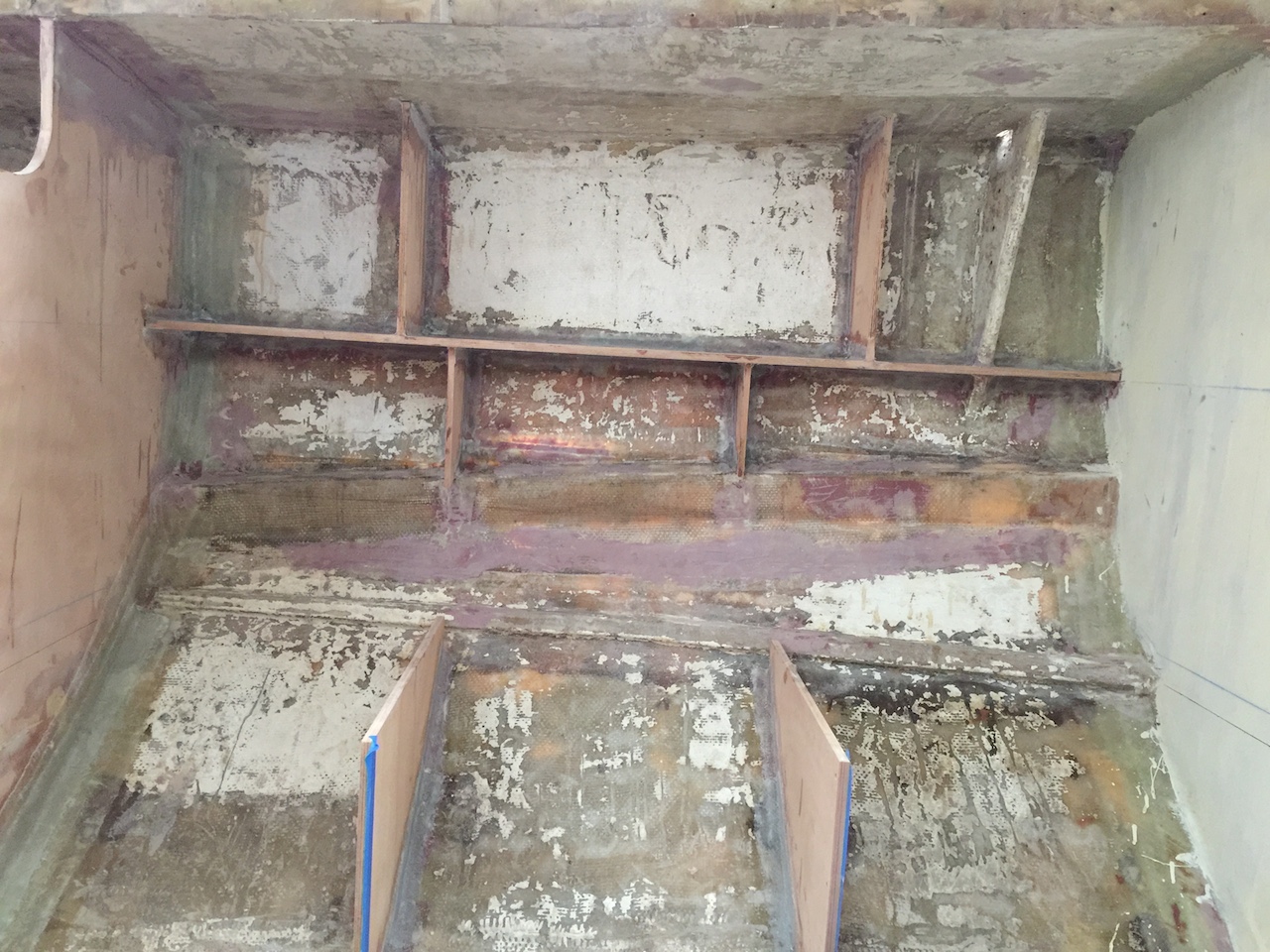
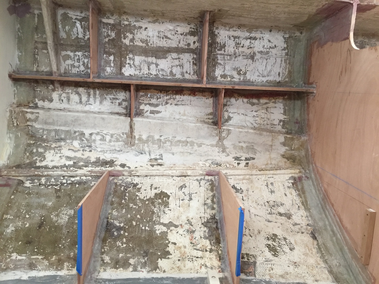
There will be no more tabbing in the salon area, so I applied white and gray primer. All locker areas will be painted gray and all shelf areas white.
COMPRESSION POST AND AFT-COMPARTMENT BULKHEAD
I tabbed the forward edge of the aft-compartment bulkhead with two layers of biaxial cloth, working with short pieces to facilitate laying them up in tight spaces.
As usual, the tabbing was wetted out in the workshop.
The next photo shows the forward side of the bulkhead after the tabbing had dried and was sanded.
I made patterns for, then cut out, two 12-inch-wide plywood boards that I shaped to fit snugly in the middle of the aft side of the bulkhead.
Using the jointer, I cut a wide rabbet along the top and bottom of one piece to accommodate the tabbing along the top and bottom of the bulkhead.
After a final test fit, I used thickened epoxy and screws to glue the boards to each other and to the bulkhead. In subsequent days, I made an epoxy fillet along the top and bottom and then installed tabbing. This arrangement serves as the compression post for the mizzen mast. Recall that there was no compression post in the original build, and the original bulkhead had bucked under the mizzen mast step.
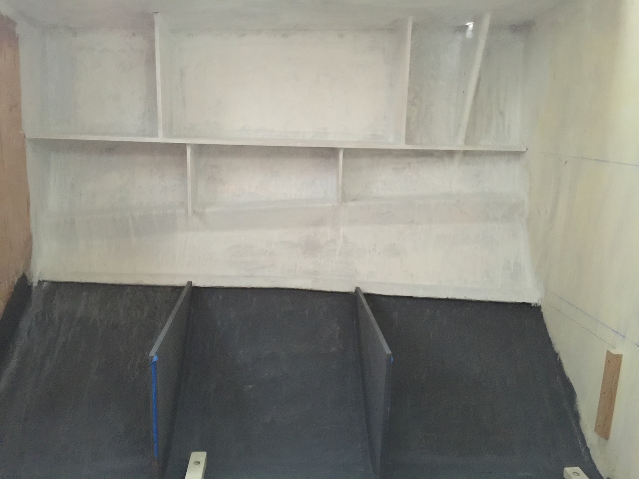
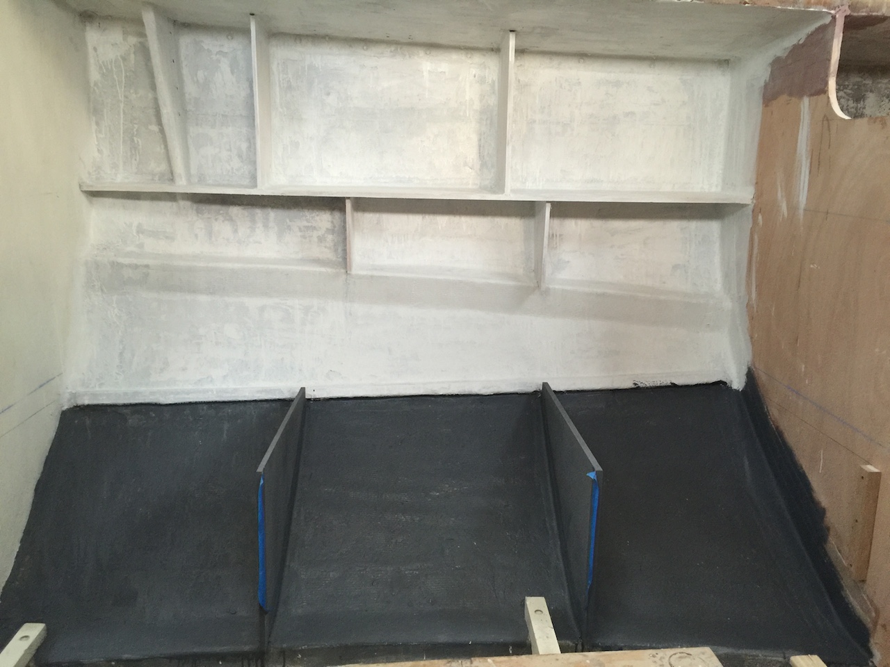
Work in this area continued with a second coat of primer and a coat of paint. The following two photos show the results.
HOLDING TANK
Two years ago, I built two integral tanks in the bilge area. The following old photo shows the tanks, full of water, just before a pressure test.
Tanks filled, awaiting pressure testing
These tanks have capacities of about 70 gallons each, and my intention was to use the aft tank for water and the forward tank as a holding tank. The plan now is to use both tanks for water and to build an integral holding tank in the forward cabin. The following are among the reasons for this change of plan:
(1) With the tank in the forward cabin, I will be able to plumb straight through a bulkhead and into the tank, which keeps all of the waste plumbing in the head area.
(2) The holding tank in the forward cabin will be about three feet higher than those in the bilge, so less pumping pressure will be required to pump out the holding tank.
(3) The space under the head floor might eventually serve as the sump for a shower, and I might want to plumb a drain through the water tanks and into a gray water tank in the bilge.
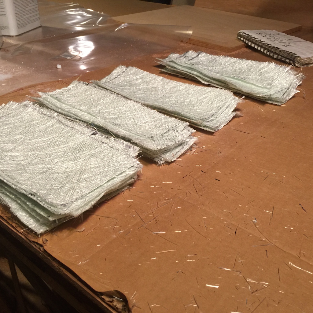
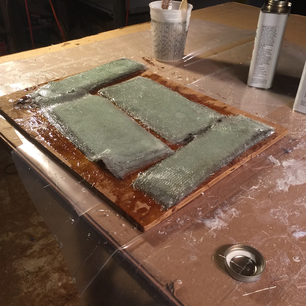
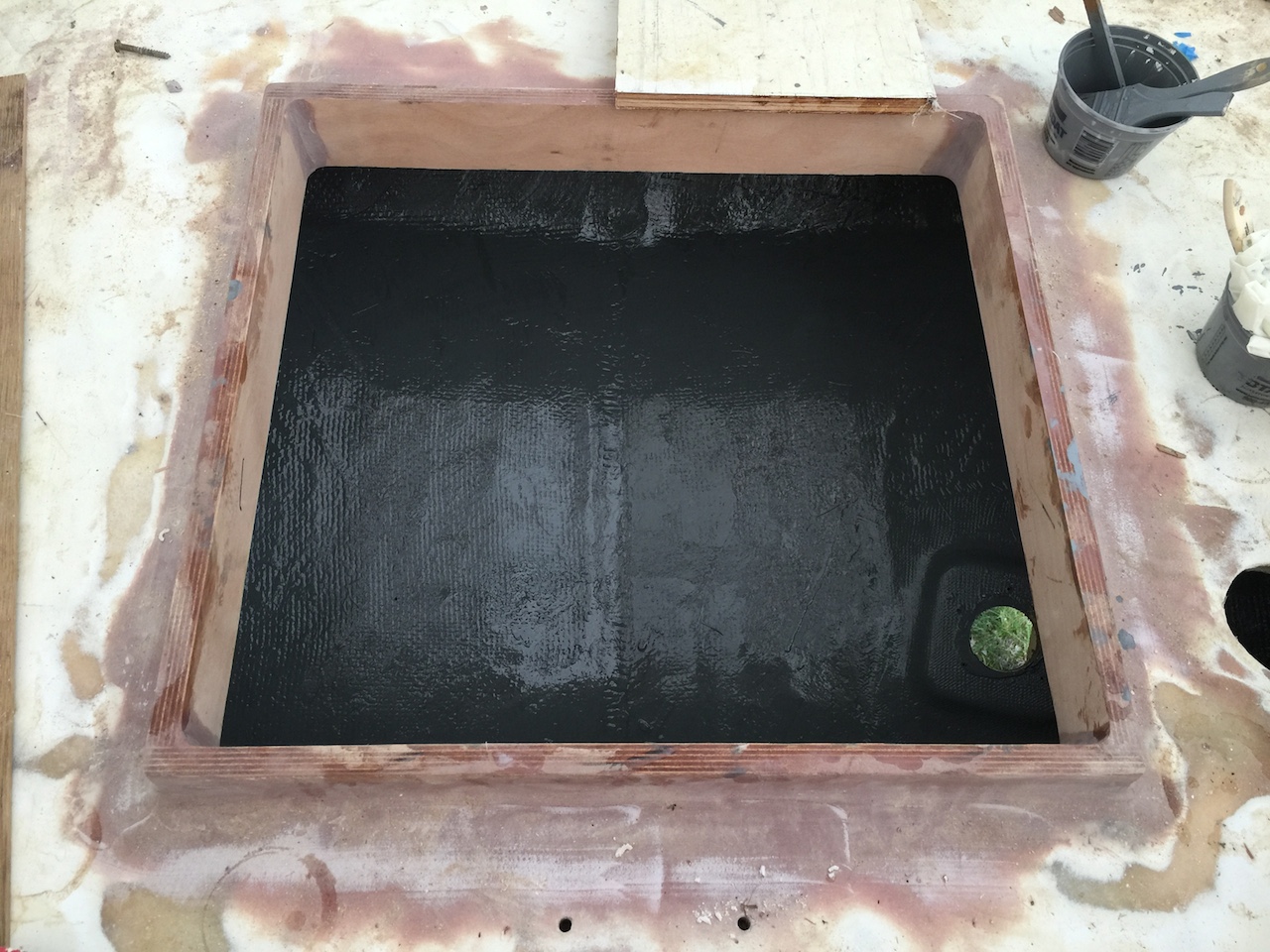
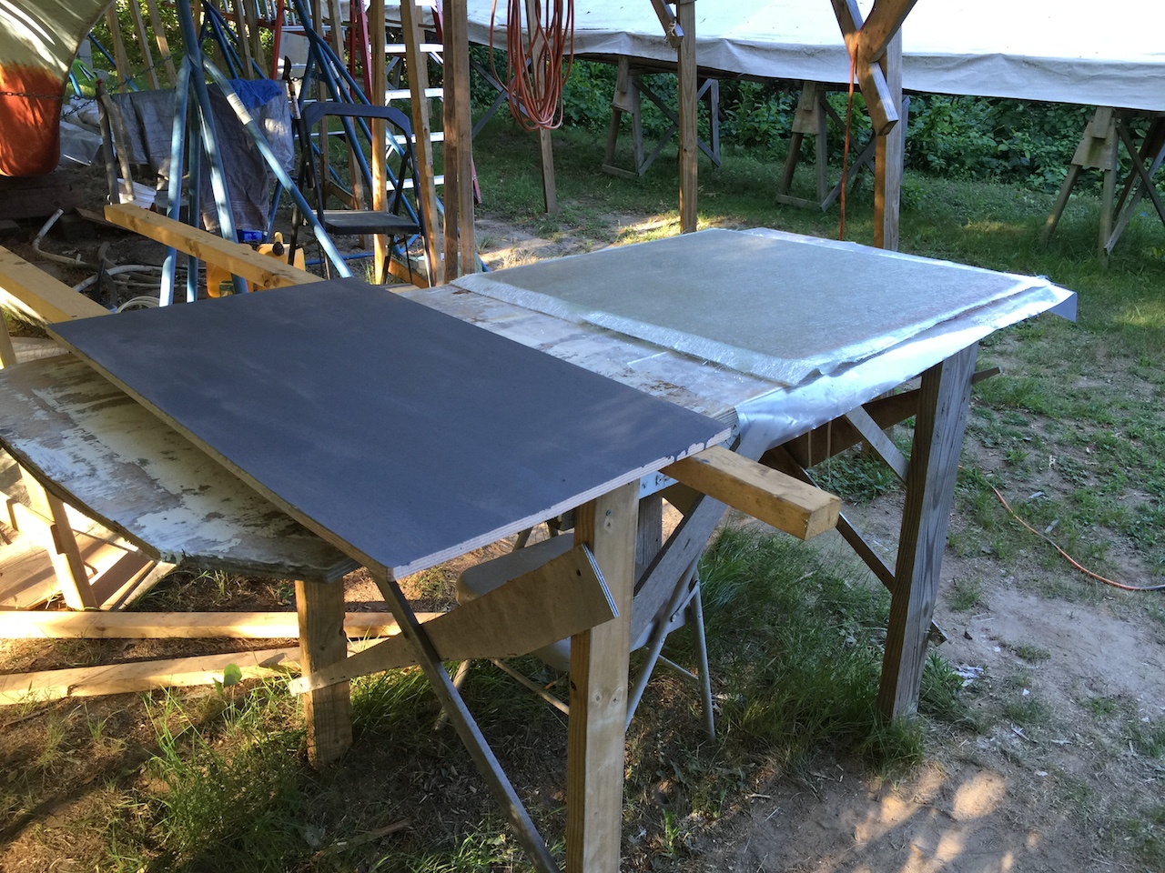
The holding tank will be on the port side in the forward cabin, and I patterned and cut the inboard side from plywood, then applied two layers of biaxial cloth followed by one layer of chopped-strand mat. The following photo shows the glassed board, and also the bottom side of the sink-area countertop, which here has just received a coat of paint.
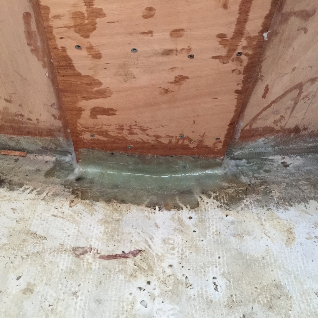
The following photo shows the inboard tank side running parallel to the port-side hull. Here it is tacked into place and ready for next steps.
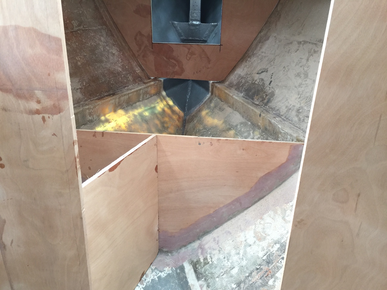
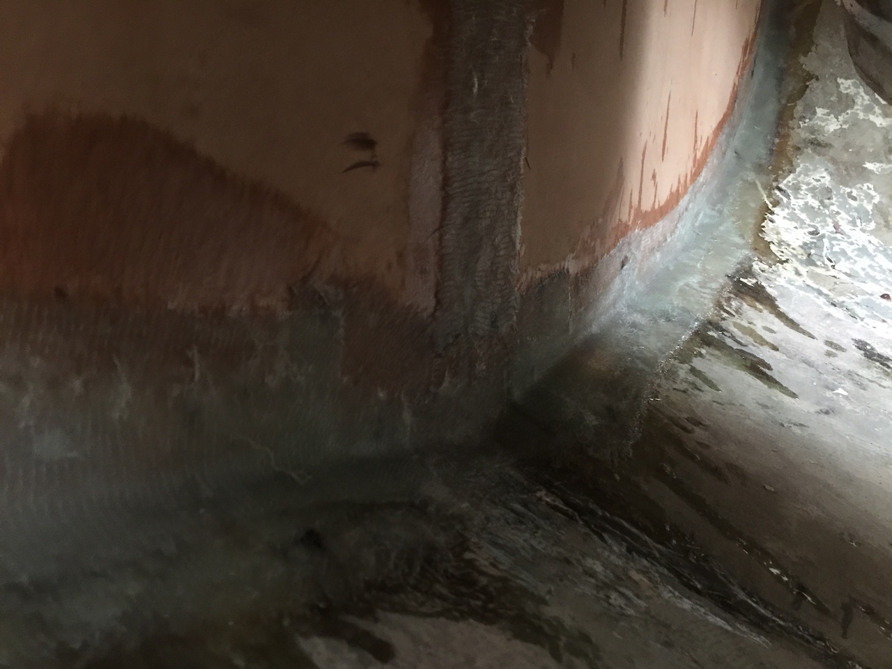
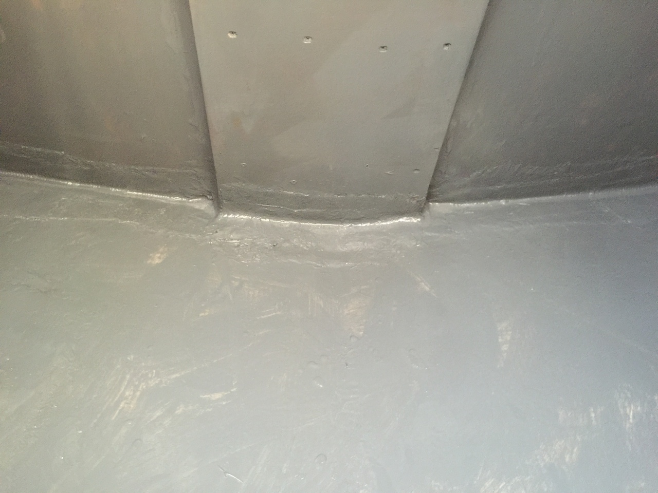
Here we are looking aft and into what will be the inside of the holding tank. All sides, of course, will be coated with multiple layers of glass and all seams will be tabbed.
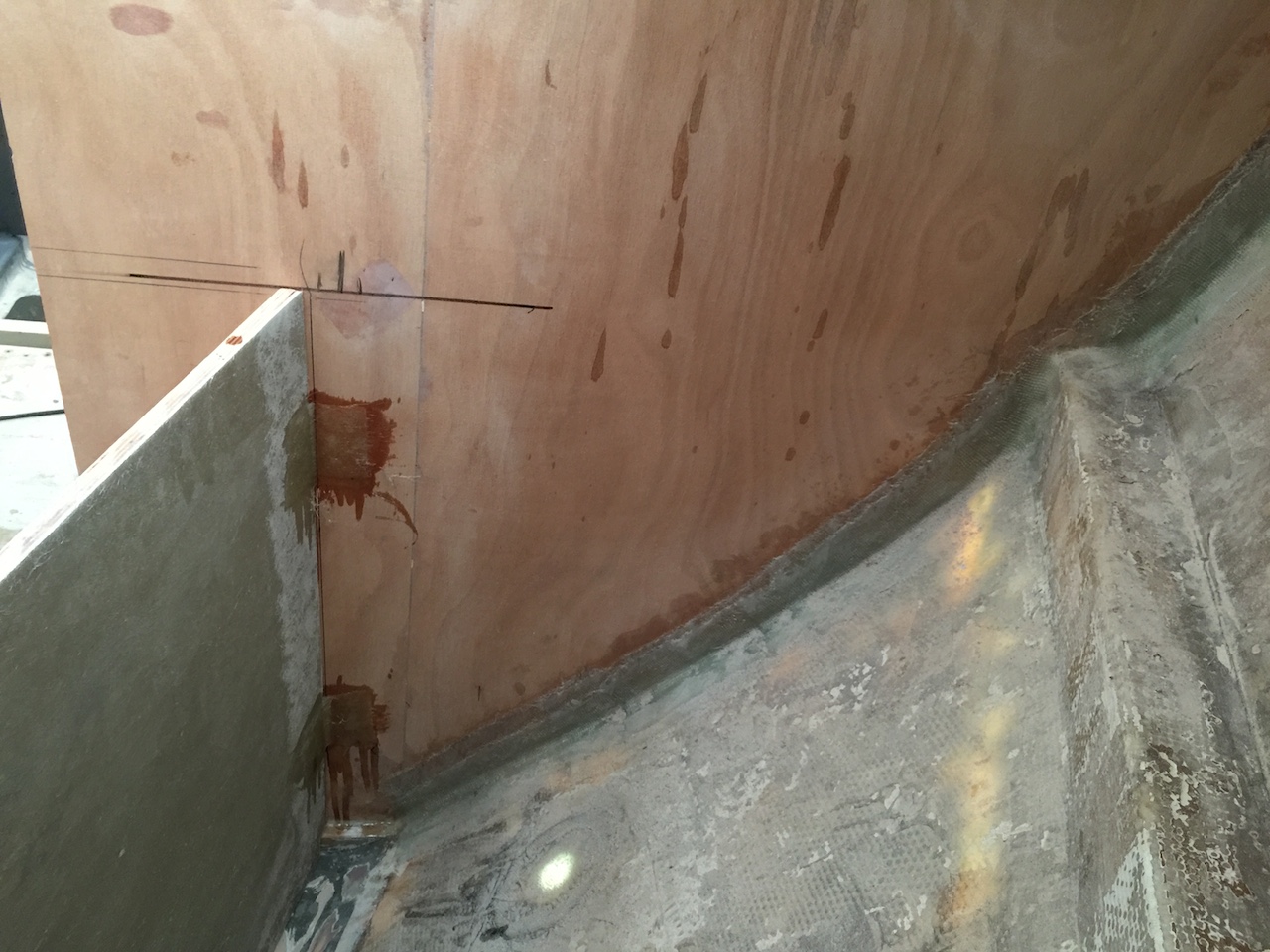
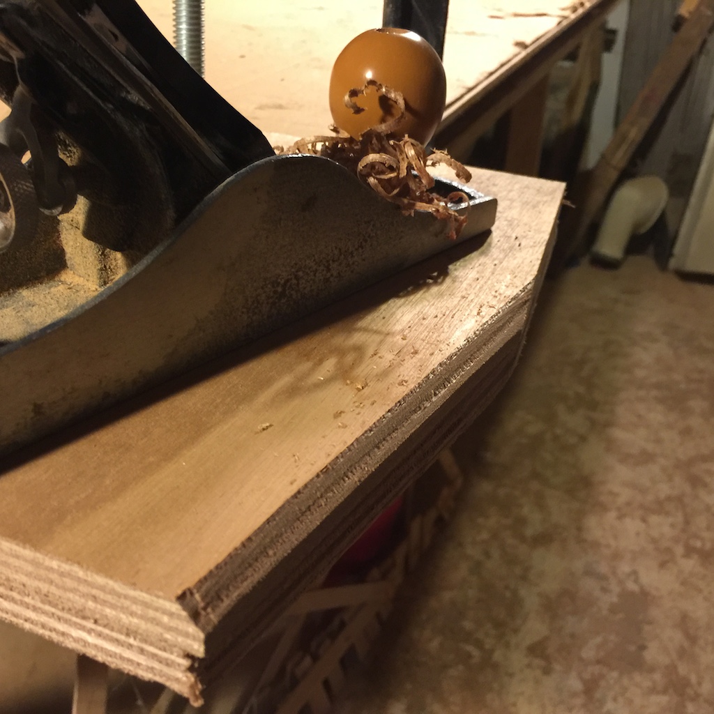
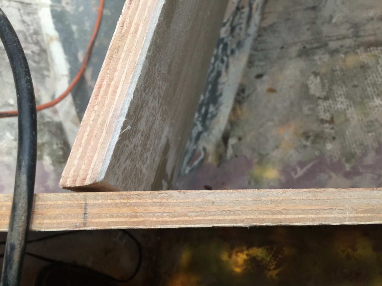
Next we can see a cross section of the inboard side, where you can see the relative thickness of the glass layers. There’s still a long way to go here, and more on the holding tank later.
FOREPEAK
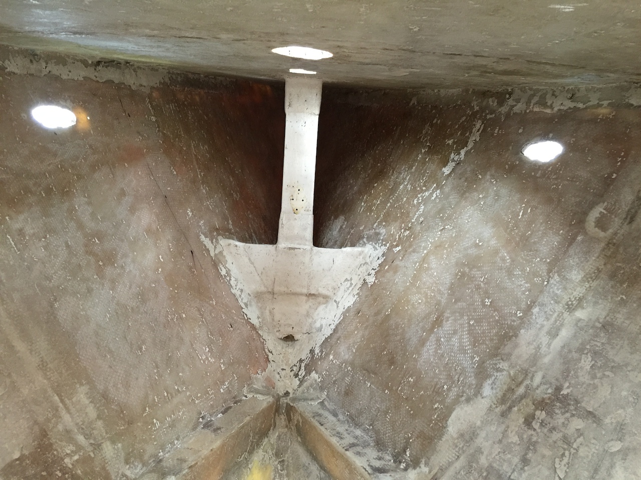
The forepeak area has been scraped and sanded, and is ready for primer and paint. The Samson post makes reaching up forward difficult, and the difficulties like those here are rivaled only by those in the aft compartment.
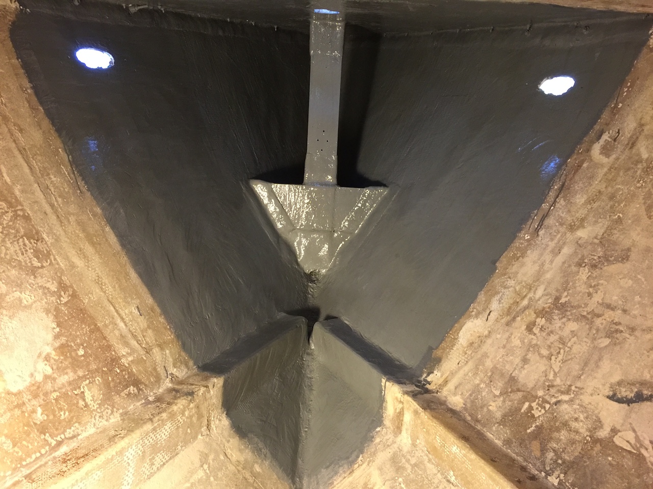
Nevertheless, I applied a coat of primer, then paint, and it was time to install the bulkhead that separates the chain locker and the forward cabin.
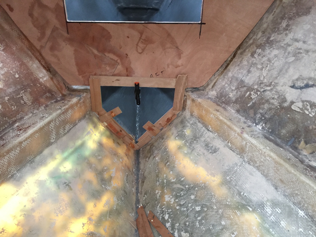
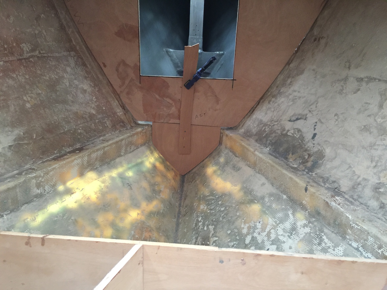
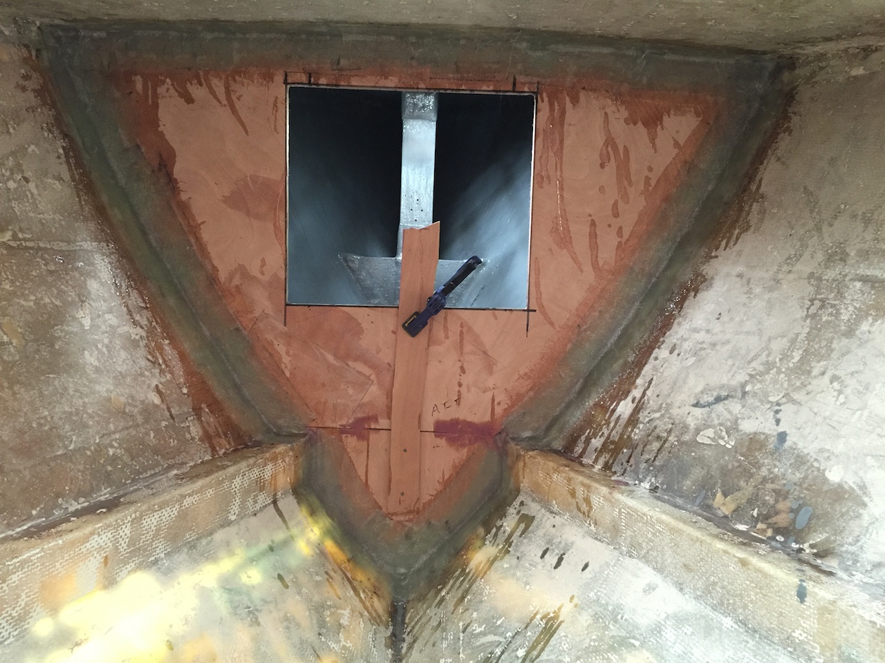
You might recall that this bulkhead was too big to fit into the cabin in one piece, so I made the part above the stringers in one piece, and the photo below shows the pattern used to cut out the rest.
The two pieces were joined dry, as follows.
Next, I followed the usual procedure to fillet and tab the aft side of the bulkhead.
The next steps here will be to tab the forward side, then prepare for priming and painting.