3/11/23: Through Hulls, Wiring Panels
Goal launch date is end of June, so 16 weeks to go.
THROUGH HULLS
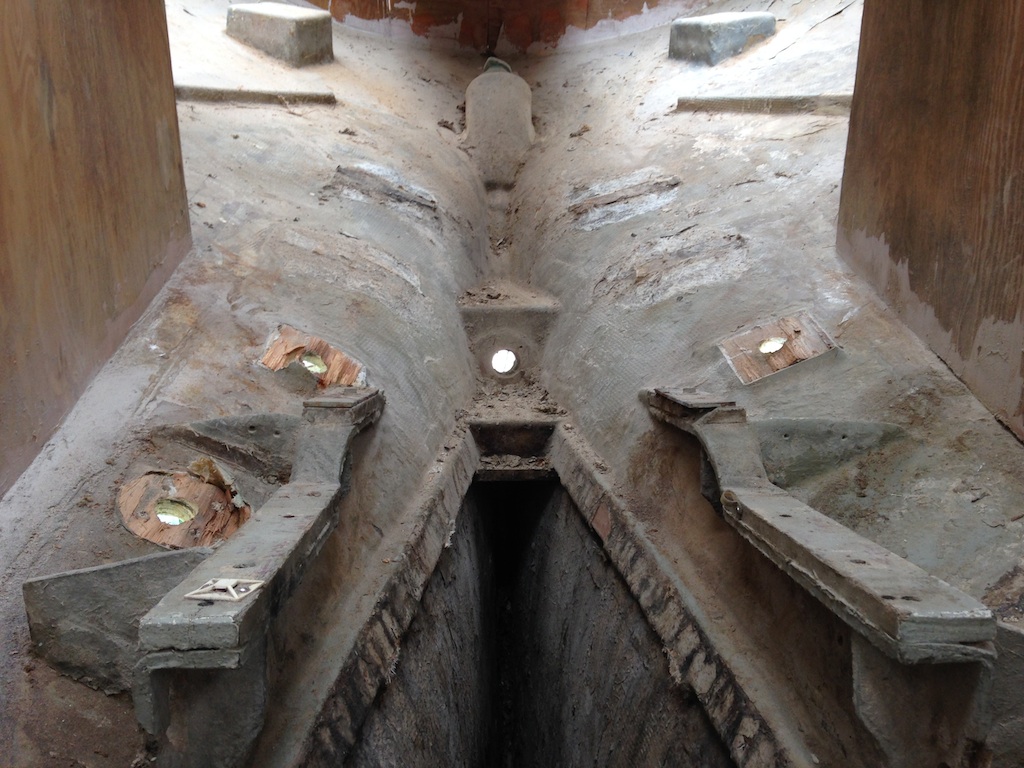
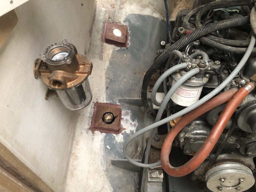
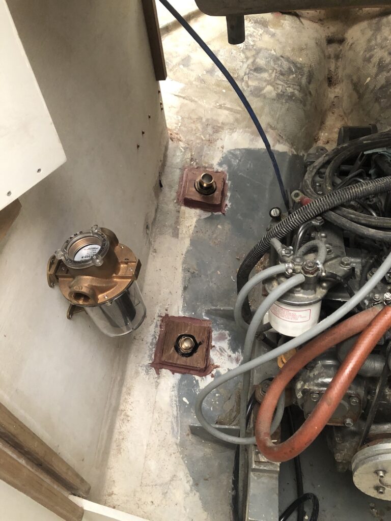
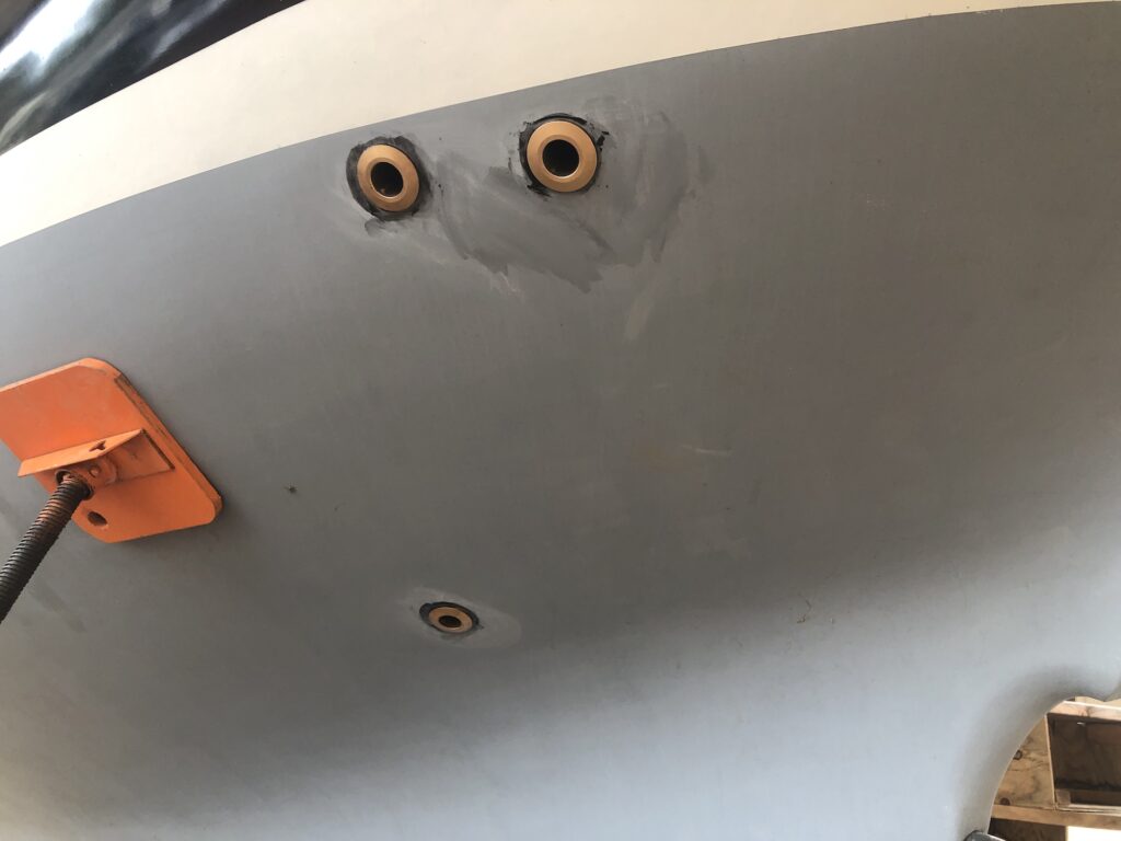
RUCKLE will initially have eight through-hulls: Two for the cockpit drains, two for bilge pumps, one for raw-water engine intake, one for sinks drain, one for head intake, and one for holding tank out. Long ago I deconstructed and glassed in the old through-hulls. My thinking at the time was that I would probably want to find new locations due to a new layout, but in the end I could have reused some of them. The old photo below shows the holes for the engine intake (starboard of the engine bed) and the cockpit drains (aft of the engine bed). The hole amidships is for the stern tube.
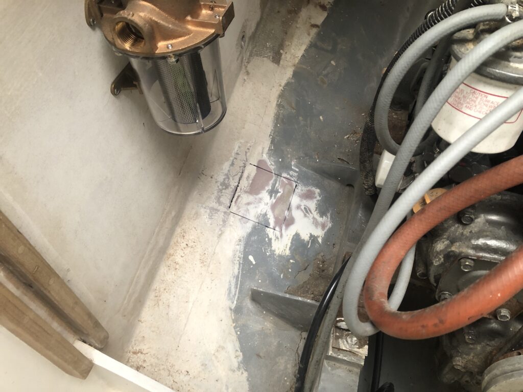
I moved these holes a few inches outboard, and the image below shows a square trace that marks where I’ll add blocking for the engine intake hole.
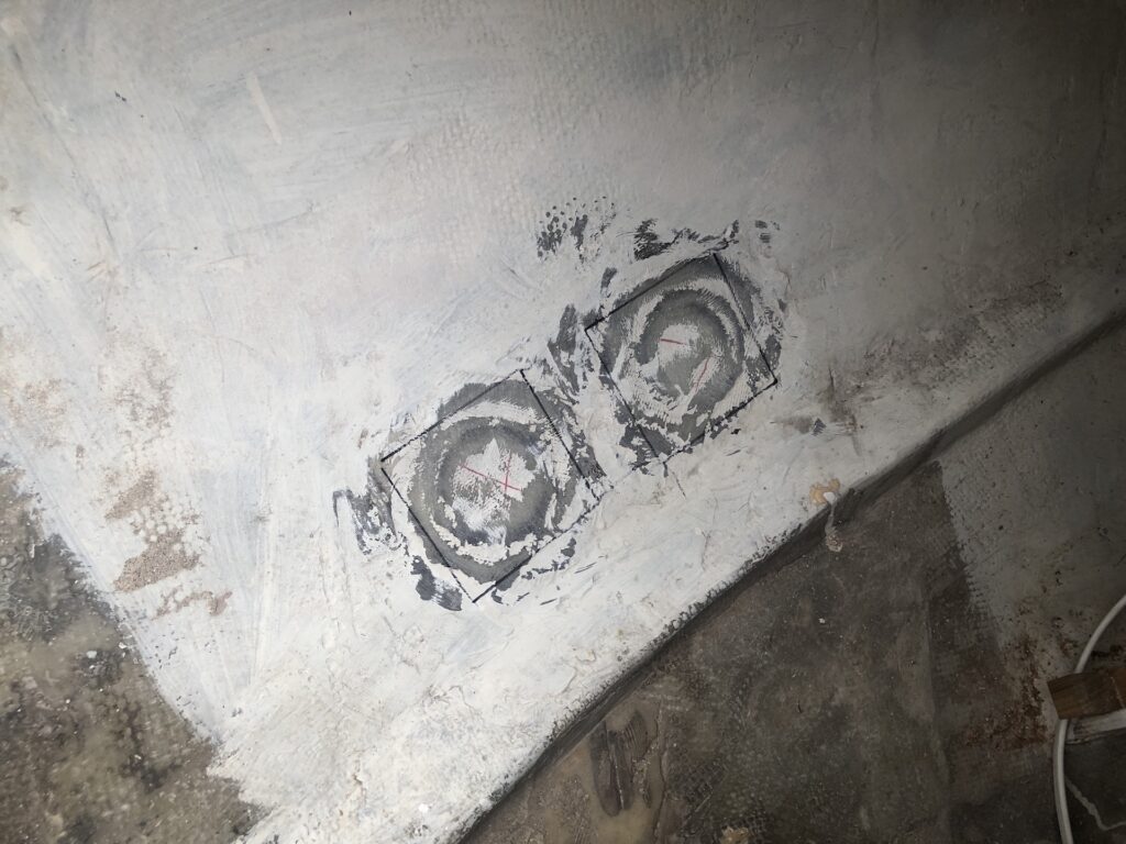
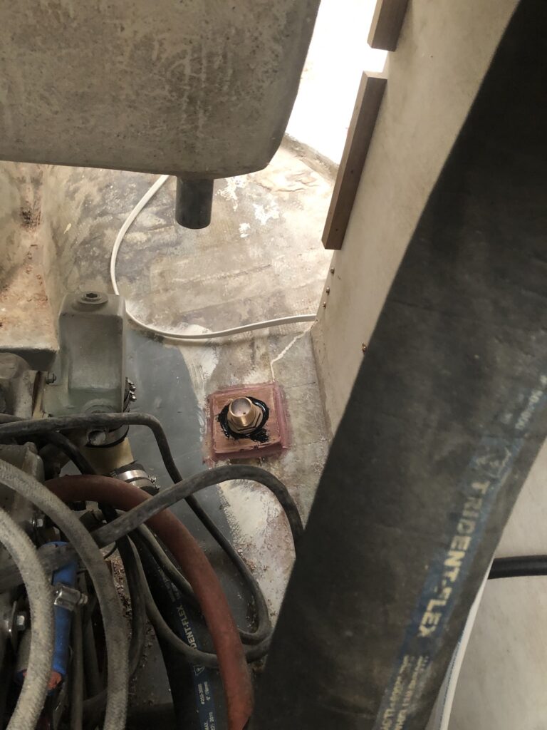
This photo is looking down into the cockpit locker area and this is where the bilge-pump holes will go.
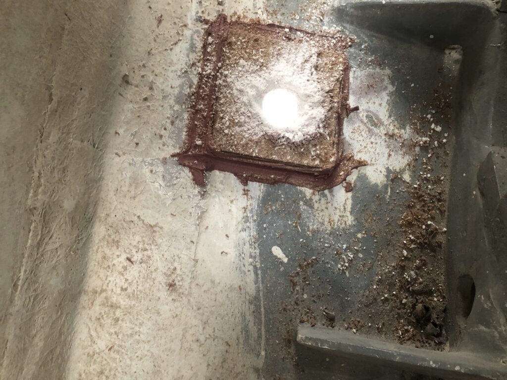
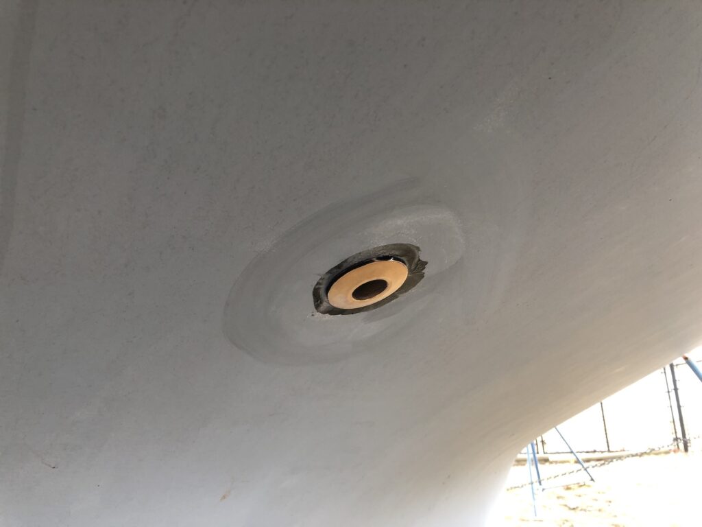
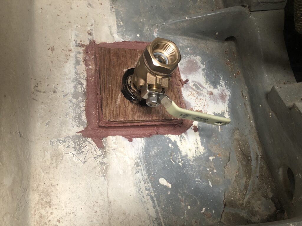
The blocking is simply an epoxy-saturarted square of 5/8 marine ply bedded in thickened epoxy. The image below shows the bored-through blocking for the raw-water intake.
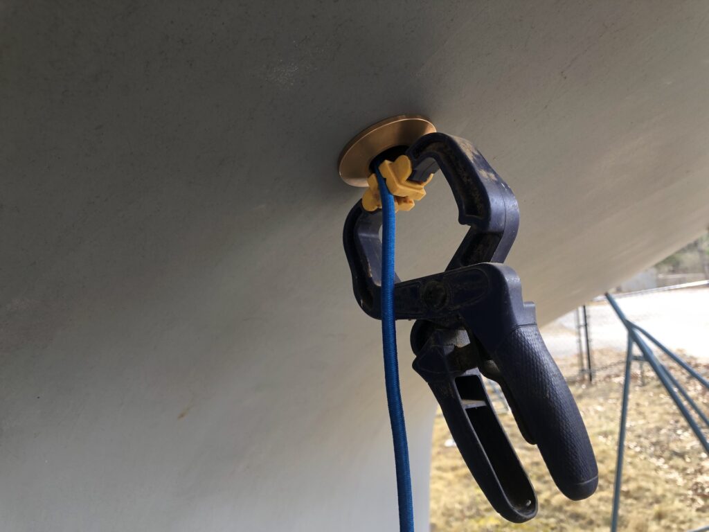
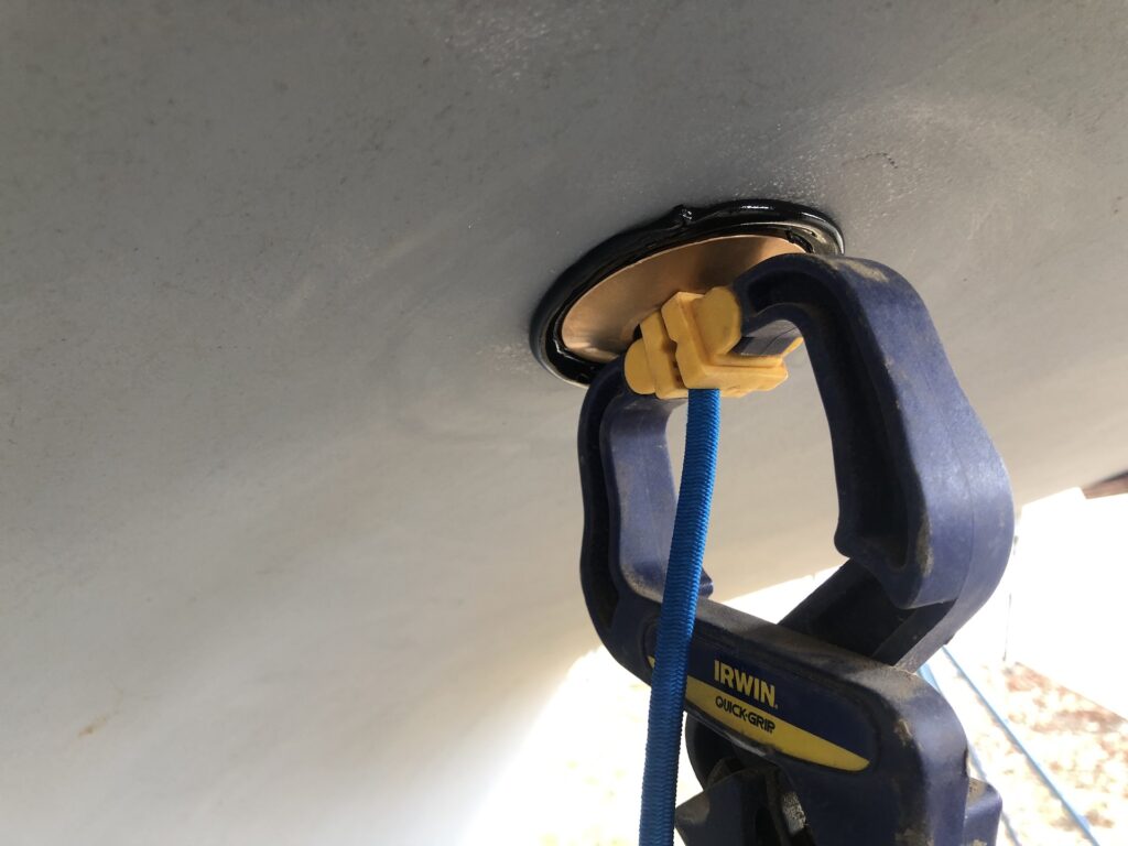
The through-hull must be held place from the outside while the nut is tightened on the inside. I tied some bungee cord off inside, and used a clamp outside to do this.
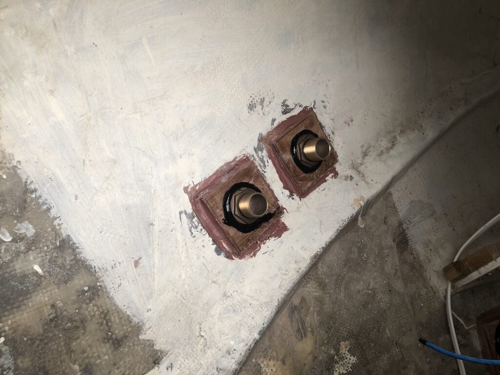
First a dry fit.

These are bedded with 4200.
Here I’ve finished the engine intake through hull and bored the hole for the starboard cockpit drain.
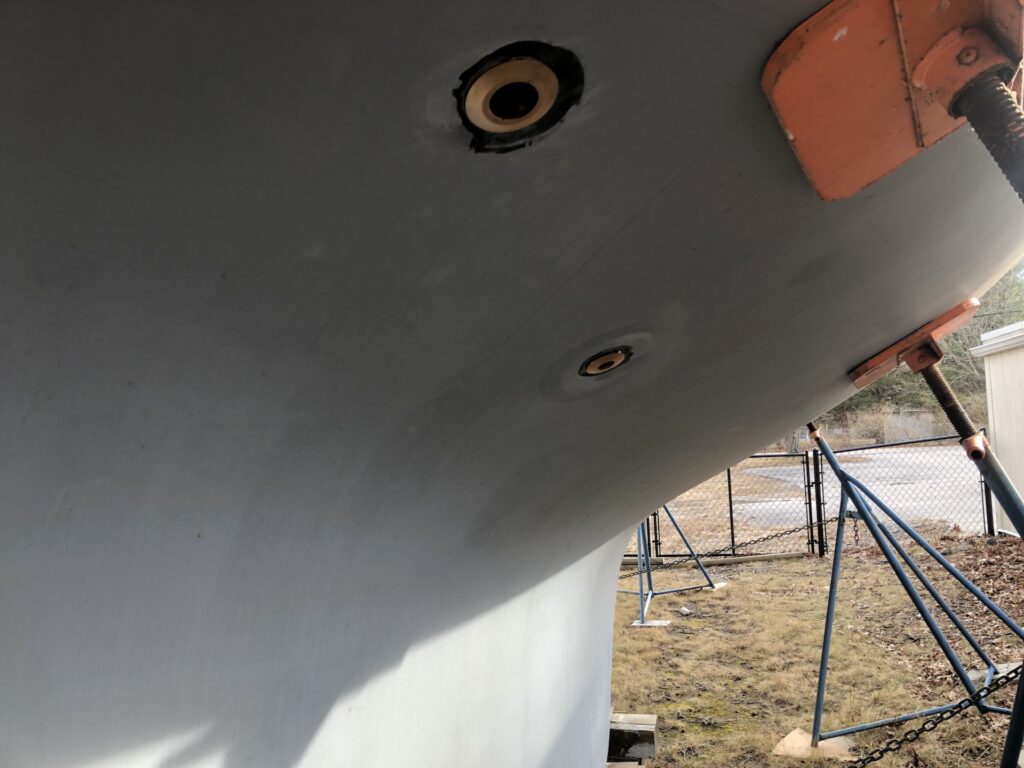
Next, clean up the squeeze-out on the outside.
Fast forward, and here are the 1″ and 1.5″ through hulls on the starboard side.
Cockpit drain port (1.5″):
Bilge pumps (port side, 1.5″):
On the outside starboard:
And port:
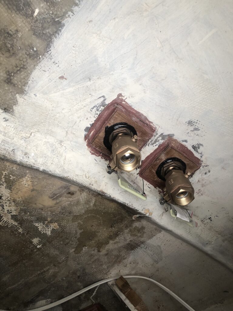
The next day, after the sealant had some cure time, I installed the ball valves on each of the five through hulls. Here is the engine intake:
Here are the those for the bilge pumps:
PANELS FOR WIRE (& etc.) ATTACHMENTS
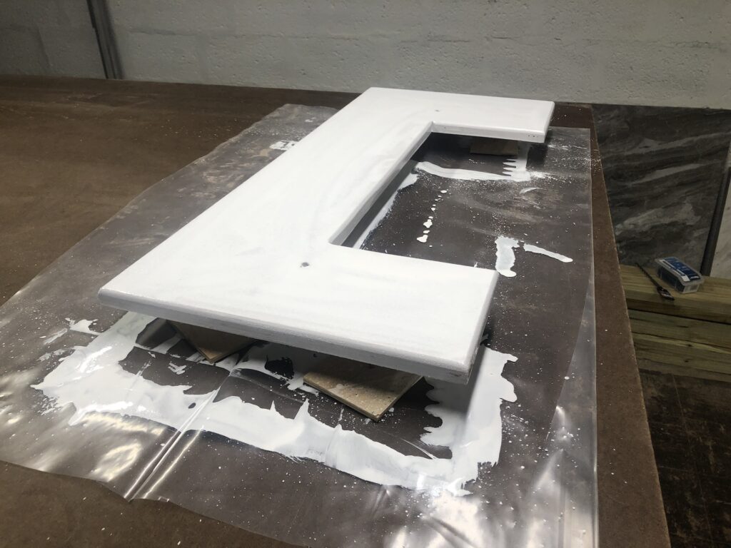
The areas above and around the engine, and around the electrical panel, will be busy with wires and hoses, and having neat wiring is facilitated by having places to attach wire clamps. The one below (made from 3/4-inch marine plywood and has received a coat of primer) is for above the engine.
Another panel will be installed in the aft hanging locker. The bulkhead would have been sufficient, but the panel allows for slightly deeper screws than otherwise would have been possible. Here I’m making a template for the panel in the usual way:
The dry fit:
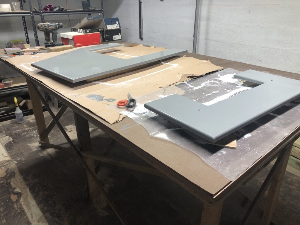
Painting both panels:
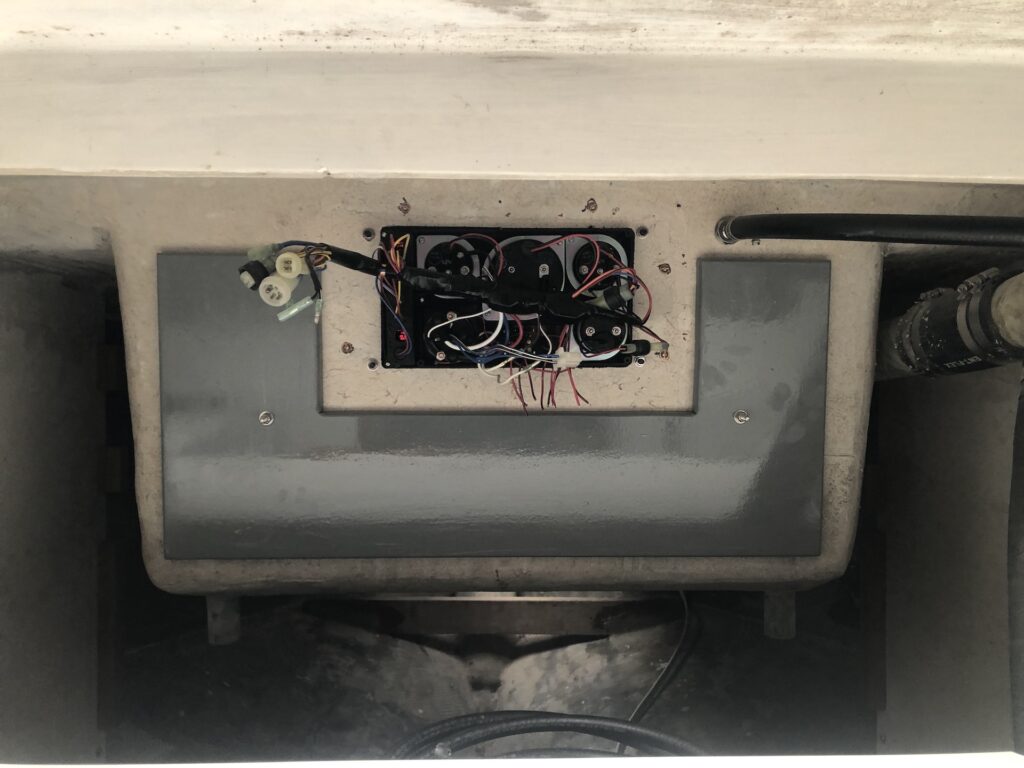
Here is the over-engine board after final installation:
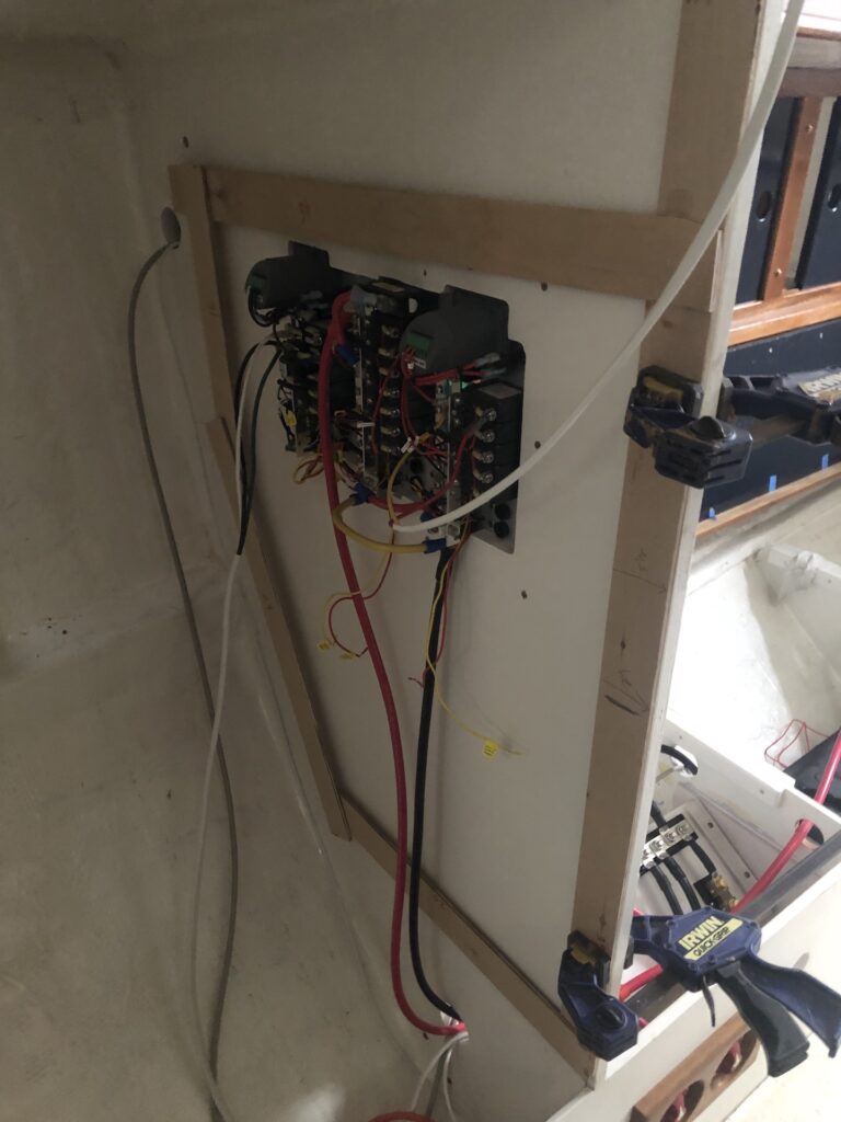
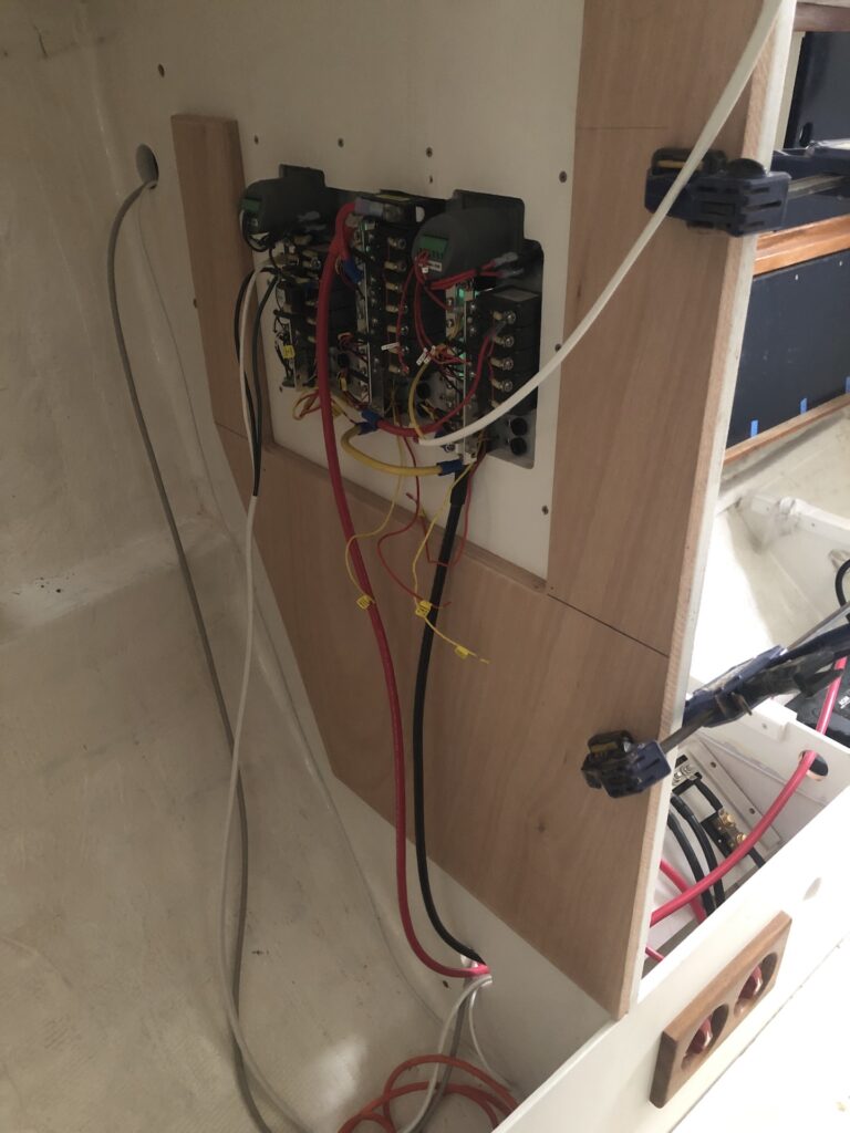
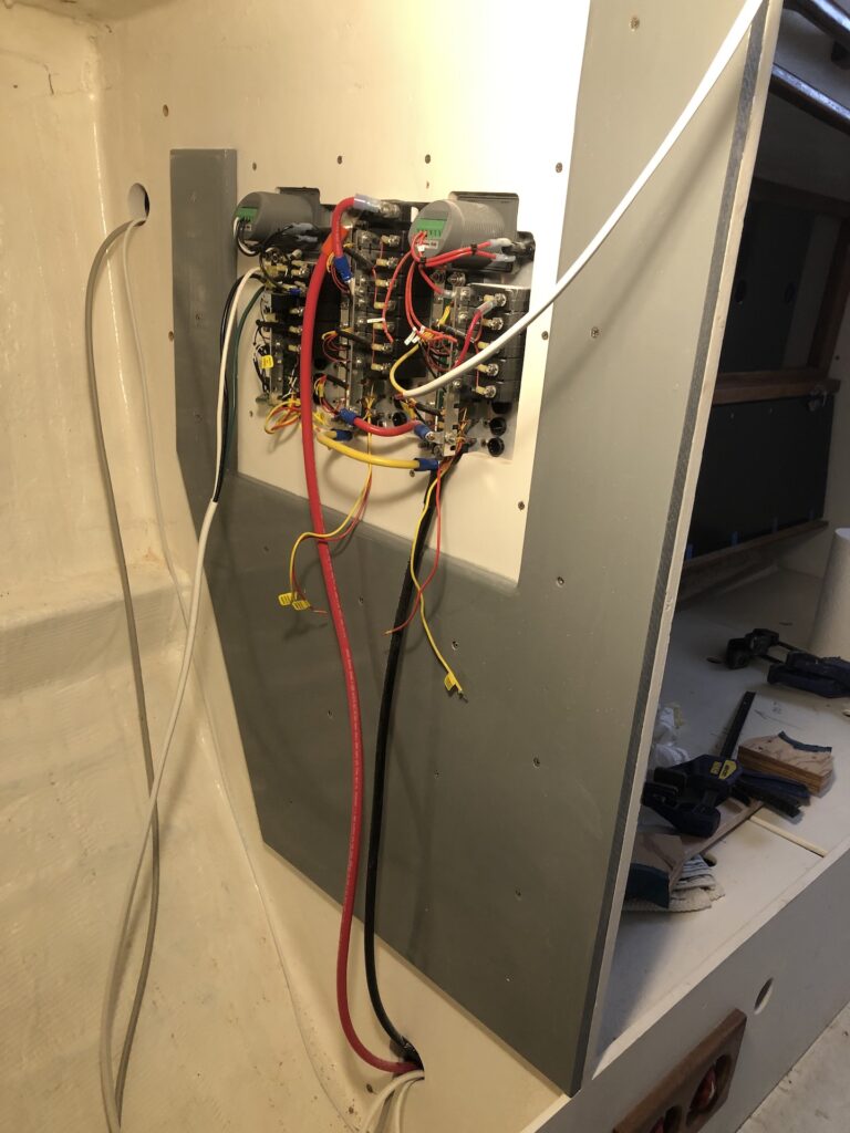
Here is the behind-electrical-panel board after installation:
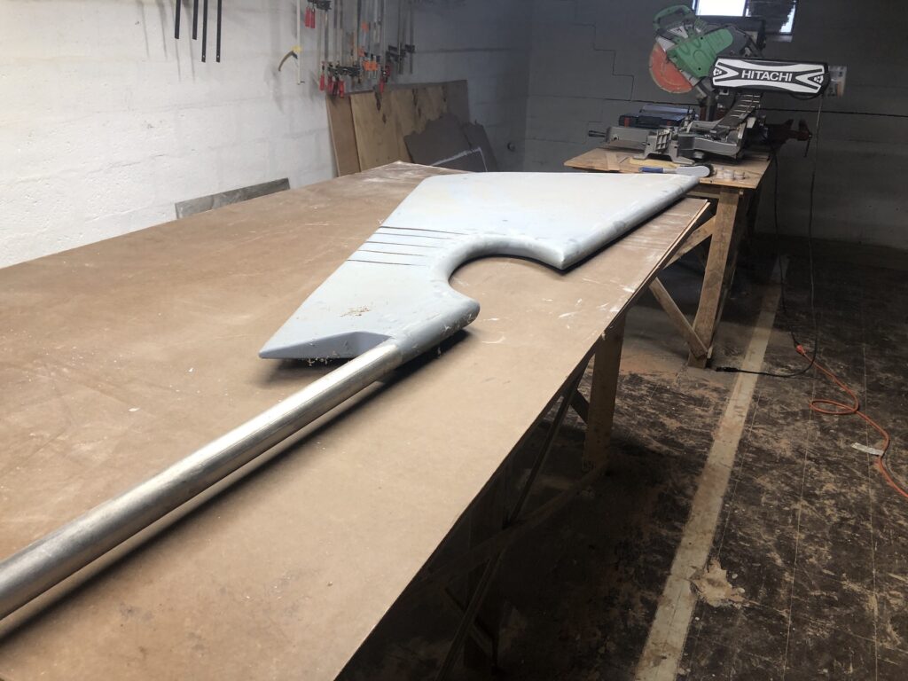
RUDDER
I’ve moved the rudder to the basement to begin solving the rudder problems. More on that later.
Jean
03/11/2023 — 10:06 pm
Yay! 16 weeks! We are all cheering you on!
TOM HEALD
03/12/2023 — 9:03 pm
Nice work MIKE. TOM
Kath
03/13/2023 — 4:18 pm
Amazing work, Mike!