4/2/23: Bilge Plumbing
BILGE SYSTEM
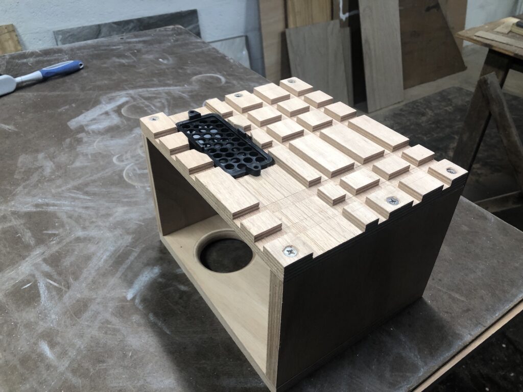
The bilge is the lowest point in a boat’s inner hull and, therefore, the place where wayward water will collect. Emptying the water in a timely fashion requires bilge pumps, and RUCKLE will two: one manual, one electric. The water’s journey to the manual pump starts at the strum box, which is the black-plastic thing you see in the image below. Its purpose is to filter out debris in the bilge water. I built the wooden box to mount the strum box, the electric pump, and the float switch. You’re seeing the bottom of the box in the image below, and the dadoed grooves permit water to move freely to the strum box.
I turned the box over do to a dry placement of the electric pump and float switch, then used some leftover sanitation hose to mock up the hose layout.
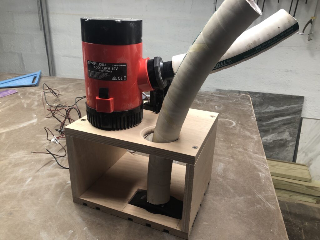
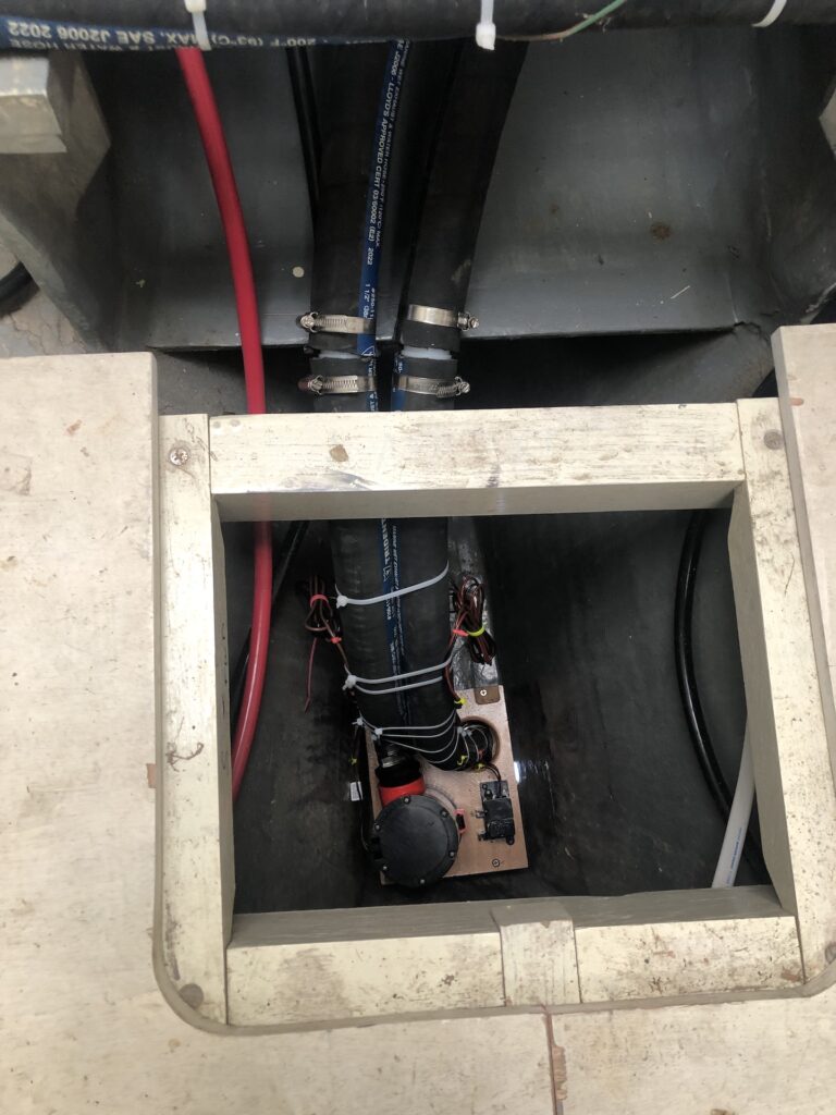
The direction of the hose coming off the electric pump was more horizontal than I liked, so I included a 90-degree barbed coupling that you can’t quite see in the image below. The following things happened between the previous image and the one below: I thoroughly coated the wooden box in epoxy, I mounted the strum box, electric pump, and float switch with screws, and I used zip ties to make a neat presentation of the hoses and wires that lead up from the bilge.
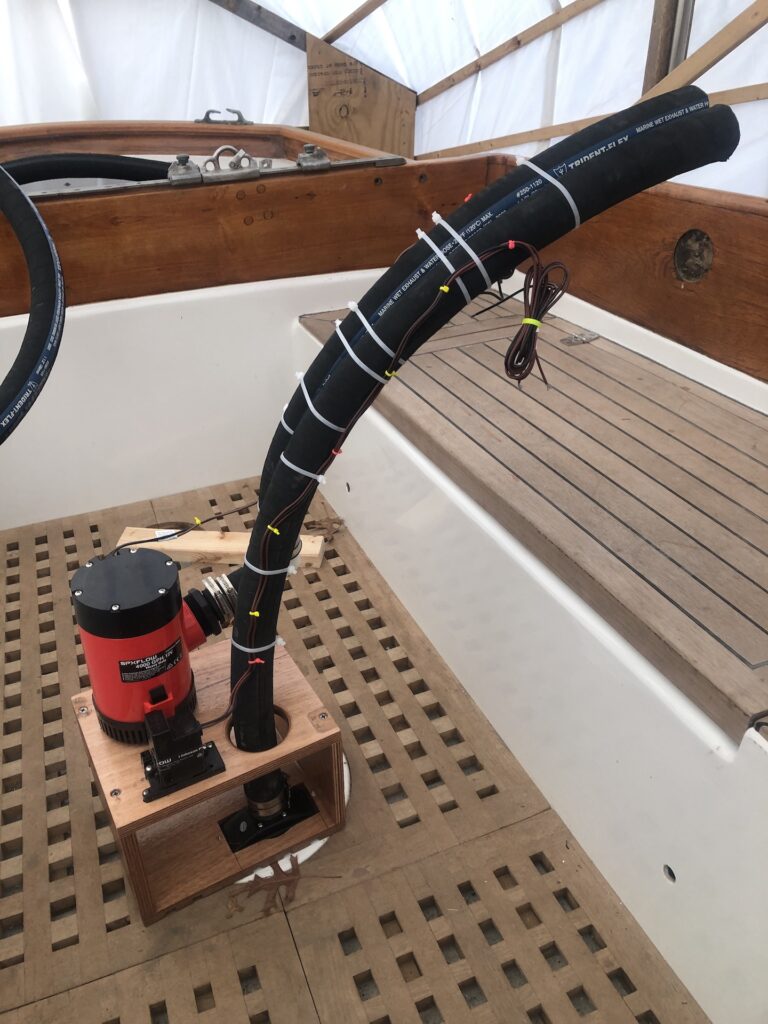
By my design, the electric pump is about 8 inches higher than the bottom of the bilge. My intention is to keep the bilge dry with the manual pump. The electric pump will kick in only if the float switch is triggered.
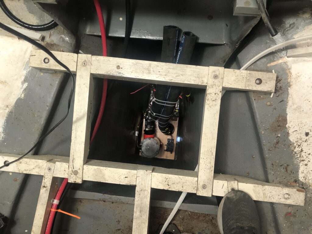
Next, I dropped the whole contraption down into the bilge, which is 3 1/2 feet below the level of the floors.
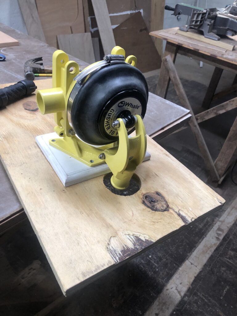
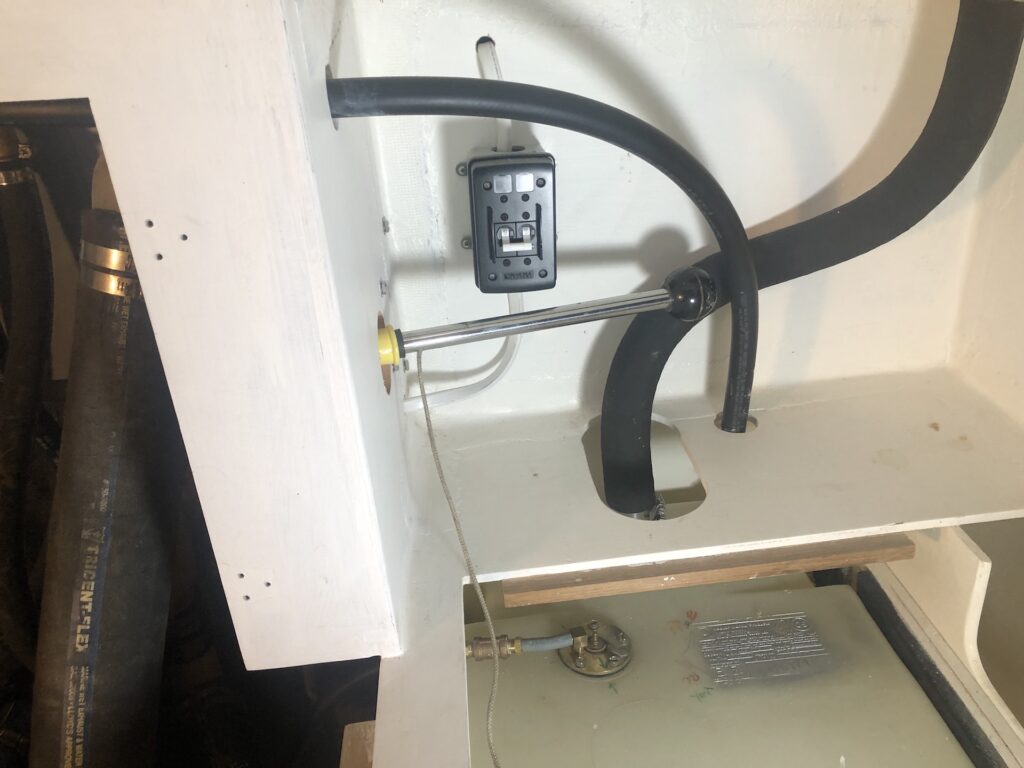
The manual pump will be a Whale Gusher (the same as the holding-tank pump) and here I’m experimenting with possible solutions for its mounting. Ideally I would have liked to mount it so I could pump from the cockpit, but the hose runs and corresponding logistics were difficult.
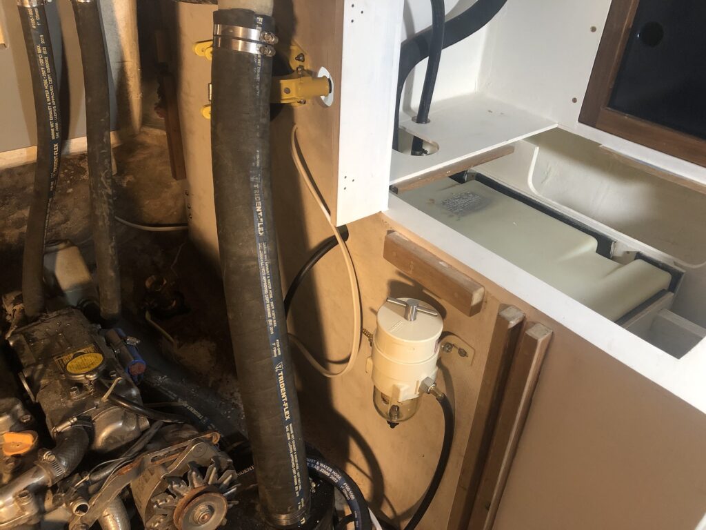
I settled on mounting it in the engine compartment, such that the pump handle would be accessible from the galley. You can see the pump in the image below, obscured by the exhaust hose. The handle will be inserted through a hole in the bulkhead from the little compartment that will eventually be covered with a curtain, door, or flap, and this will hide some fuel-system plumbing, and the breaker box for shore power. (I expect this will also be a good place to store paper towels and other light galley gear.)
Here’s a closer look at the compartment.
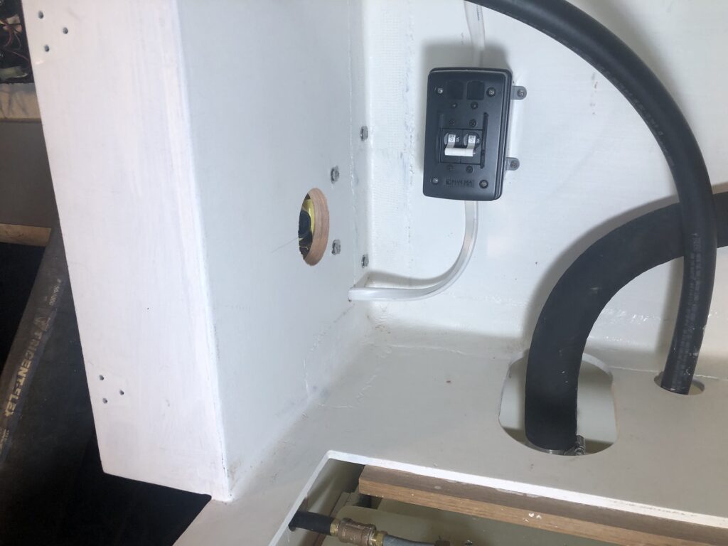
Here the handle is in the pump and thrown all the way forward:
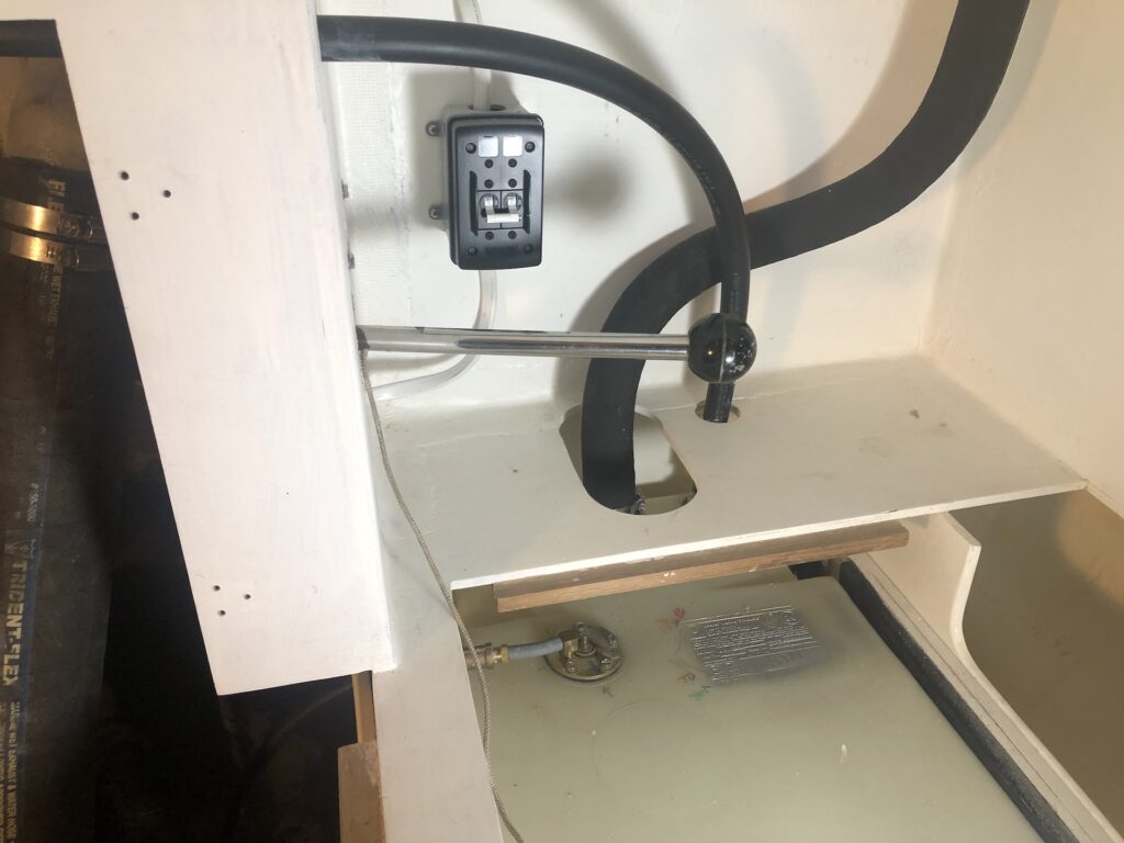
And here all the way aft, demonstrating room for a full swing.
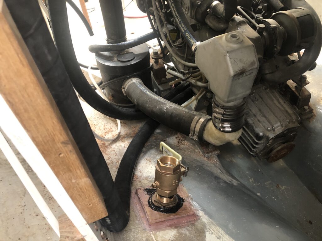
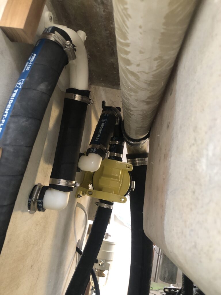
Back on the boat, I used straight connectors to continue the hose runs under the engine and up to the port-side bulkhead the flanks the engine room.
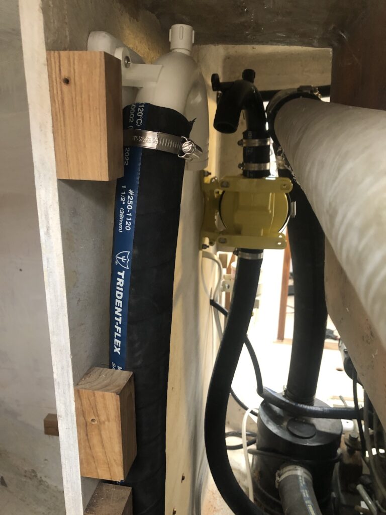
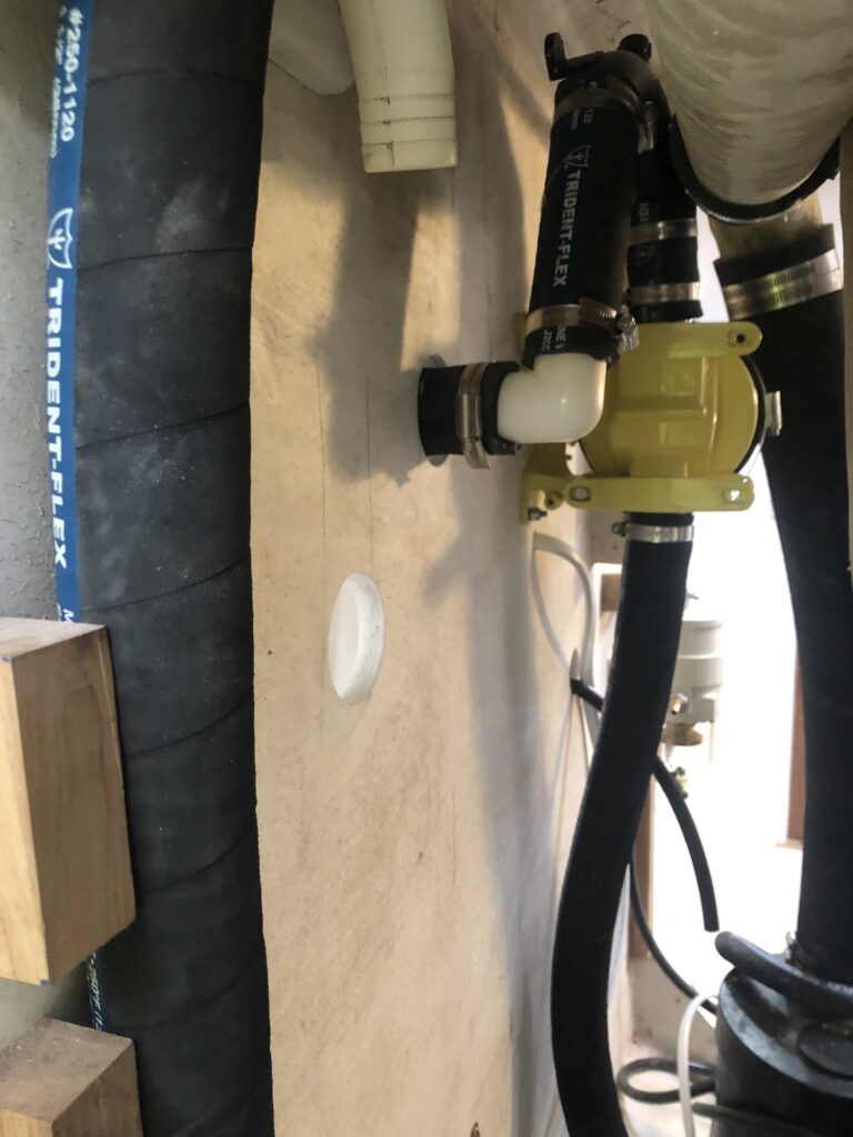
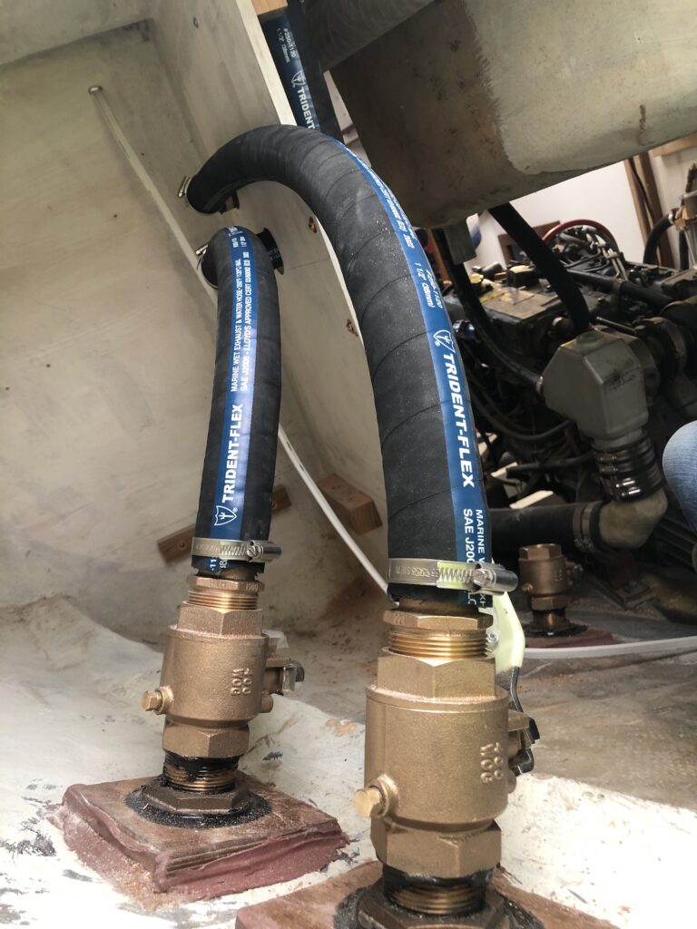
The view in the image below is from under the cockpit, looking forward, and shows the continuation of the hoses described above.
The hose from the strum box leads up to the “in” side of the manual pump. The “out” side of the manual pump leads to an anti-siphon loop (black color in the image). The hose from electric pump leads a separate anti-siphon loop (white color in the image). (If you want to know what anti-siphon loops do, then read THIS.)
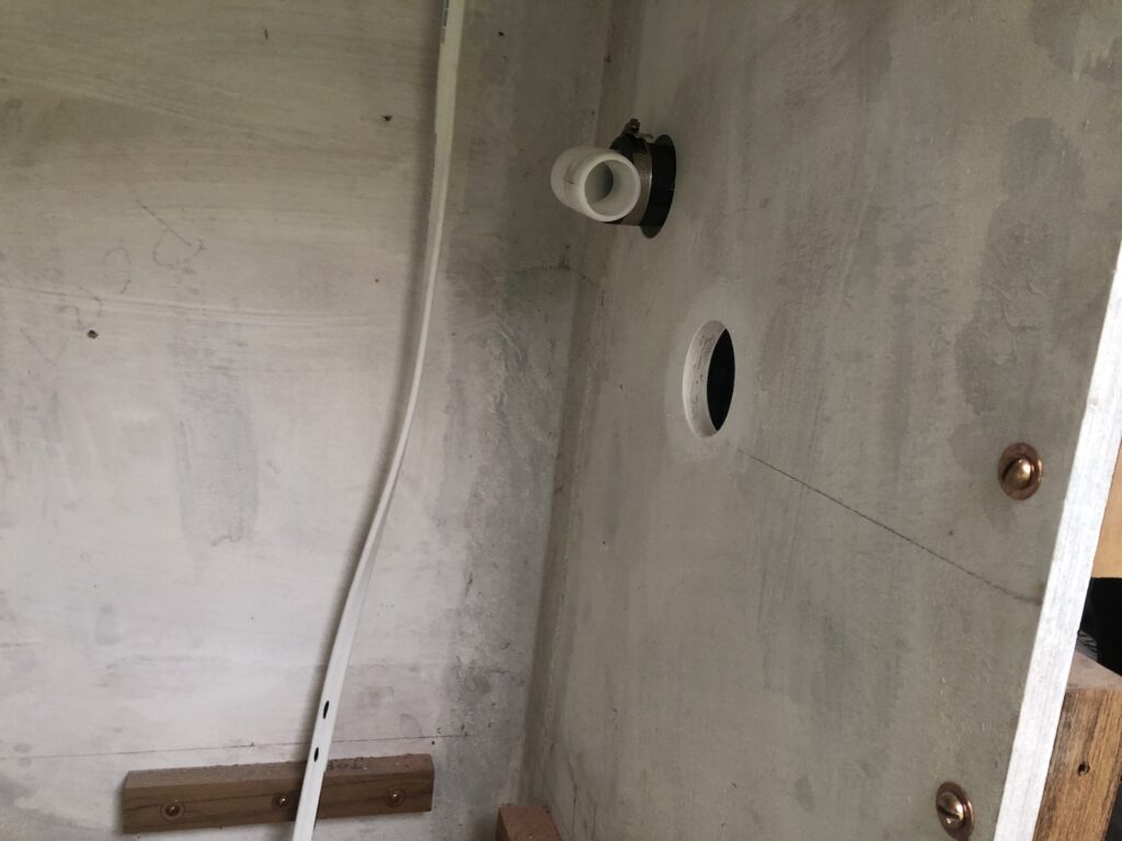
Now I had to get from the “out” side of the anti-siphon loops to the thru-hulls. I bored two circular holes in the bulkhead, and continued the runs, utilizing barbed elbows:
Out from the engine room and into the port-side under-cockpit locker:
Back in the cockpit locker, I ran the final two pieces of hose in the assembly…
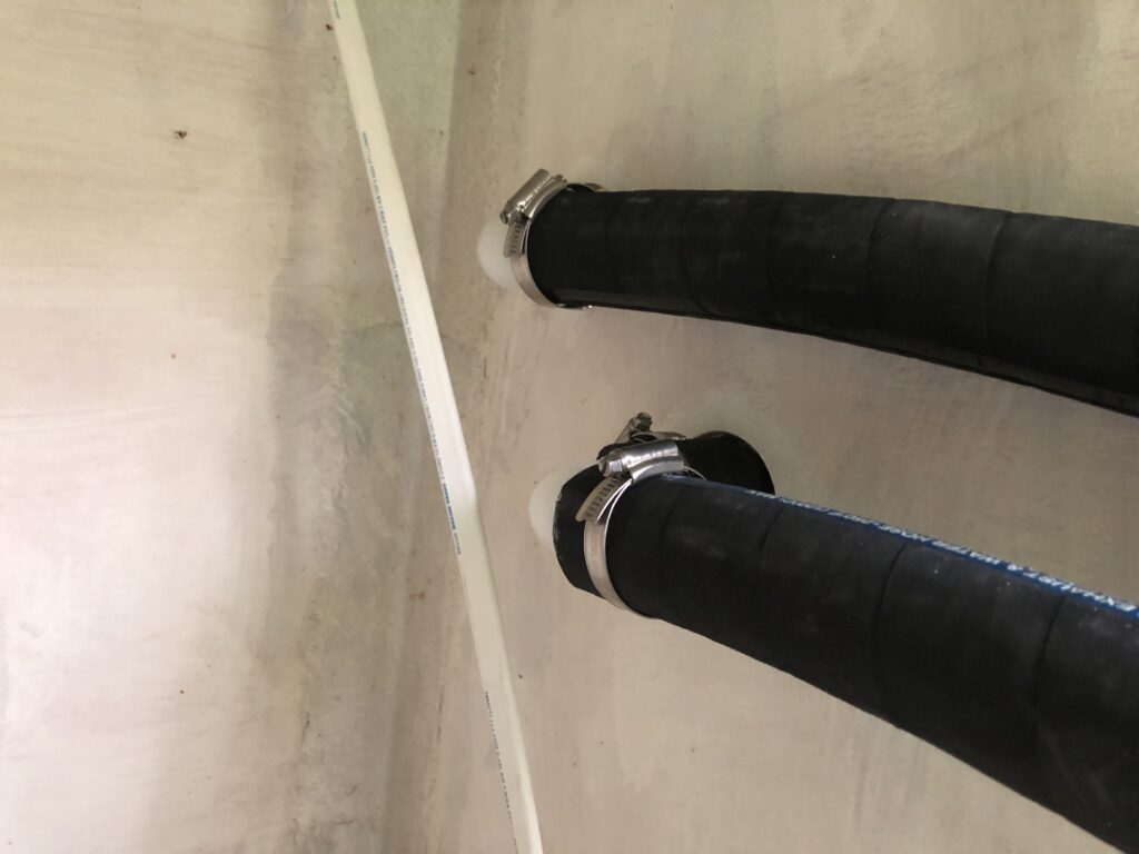
…to the thru-hulls:
Besides the two holding-tank thru hulls, which are well above the water line, these two will be the only ones subject to some jostling (due to equipment being stored in the compartment). A hose accidentally slipping off a thru-hull is normally a grave concern, but here not so much. Why? (1) The hoses are extremely stiff and robust. The image below shows the cross section and internal construction.
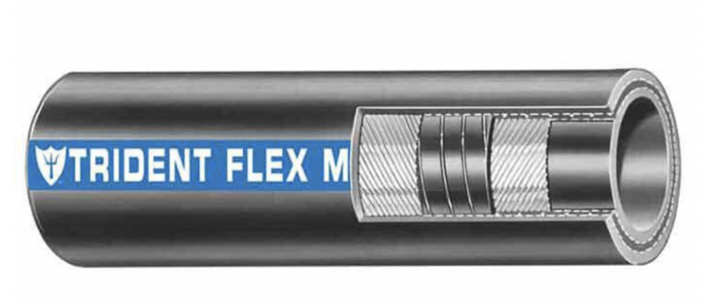
(2) I plan to store only light equipment (e.g., fenders, lines, life jackets) in this compartment. (3) These thru-hulls are just at the waterline, and I expect that the high end of the bronze pipe-to-hose fitting sits comfortably above the waterline. We’ll see after launch.
Speaking of pipe-to-hose fittings, these had not yet been bedded with sealant, so I removed the hoses, and did that:
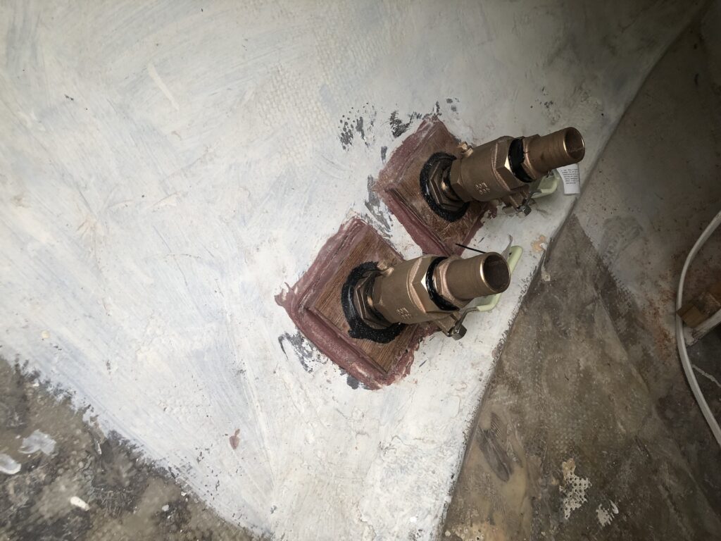
These hoses need to be out of the way anyway, for a while, as I finish painting the area.
There’s other work underway, but I’ll save that for next time.
Kath
04/03/2023 — 5:08 pm
Incredible work, Mike!