4/9/23: Freshwater Plumbing, Hot Water Heater
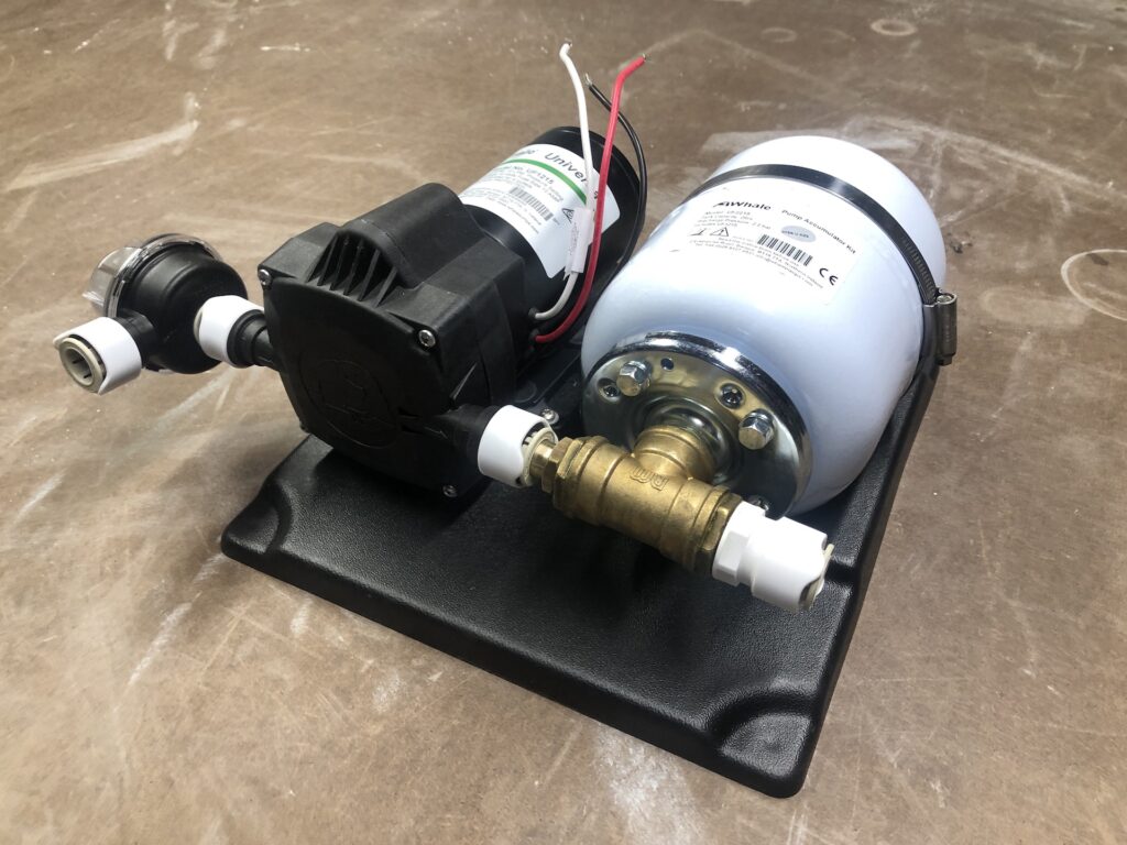
The cruising sailboats I grew up with had simple freshwater systems. One water tank, two cold-water spigots (at the head and galley sinks). Pressure was supplied by foot-operated pumps. I suspect nowadays most cruisers enjoy water supplied by an electric pump, and often both hot and cold water. The pump and accumulator tank below is a WHALE unit, and works with a system of quick-connect hoses and fittings (analogous to PEX/Sharkbite plumbing in households).
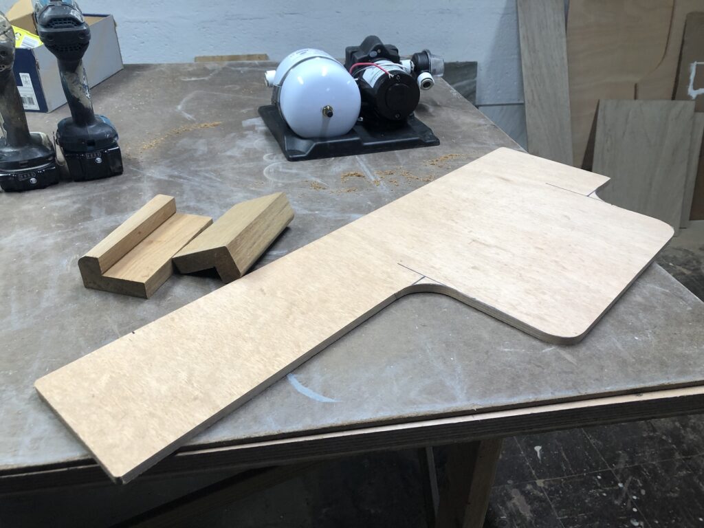
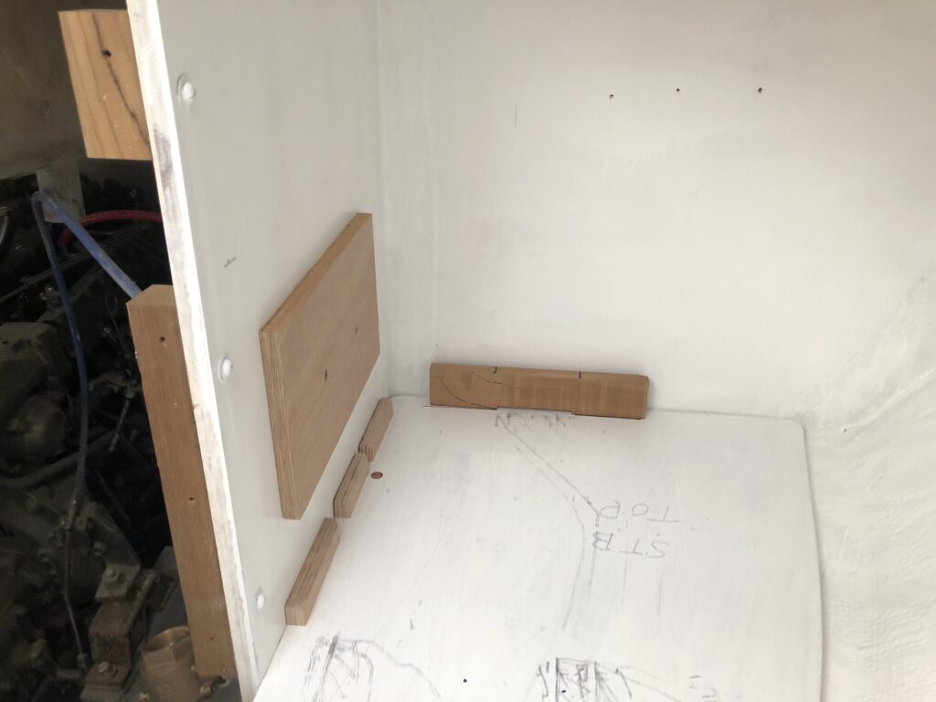
The two salon berths each have three storage compartments underneath, and five already have residents (three have batteries, one an inverter, and one acts as a junction box for the heavy electrical cables and switches). The last compartment will house the pump, and I began by making a mounting board and support cleats…
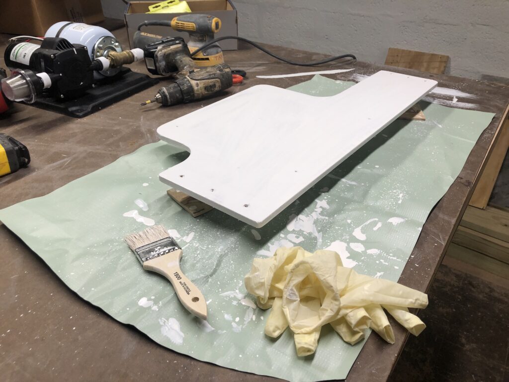
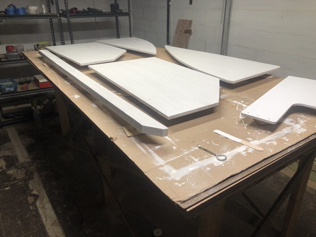
…which, of course, had to be primed and painted:
I’ll get back to the pump shortly. In the mean time I took up the floorboards and opened the two water tanks. (I built these integral water tanks back in 2014, and you can review that work HERE, HERE, HERE, and HERE.) I originally installed two 1-inch ports in each (one for vent, one for draw) and one 1.5-inch port in each (for fill). The fill ports will retain their original intent, and the tanks will be filled at the ports, not through a deck fill. The issue with a deck fill is getting the fill hose down from the deck and under the floorboards. It can be done, but at this time I don’t want to deal with it. Thus, for now a tank will be filled by lifting the floorboard over the fill port and leading a hose into the cabin. No big deal.
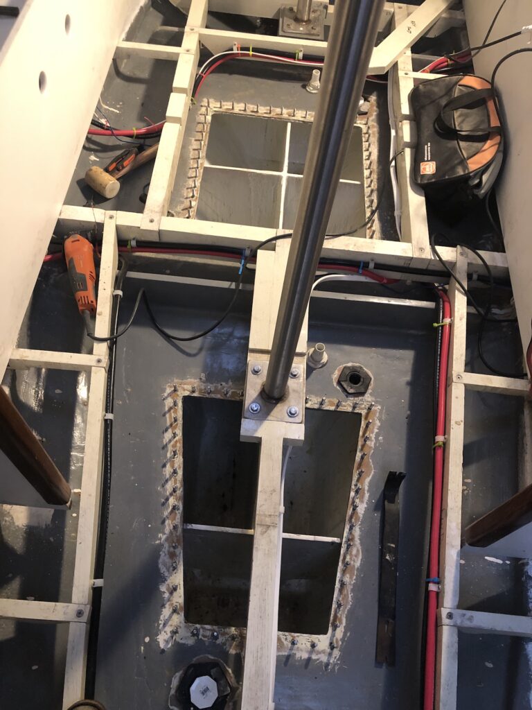
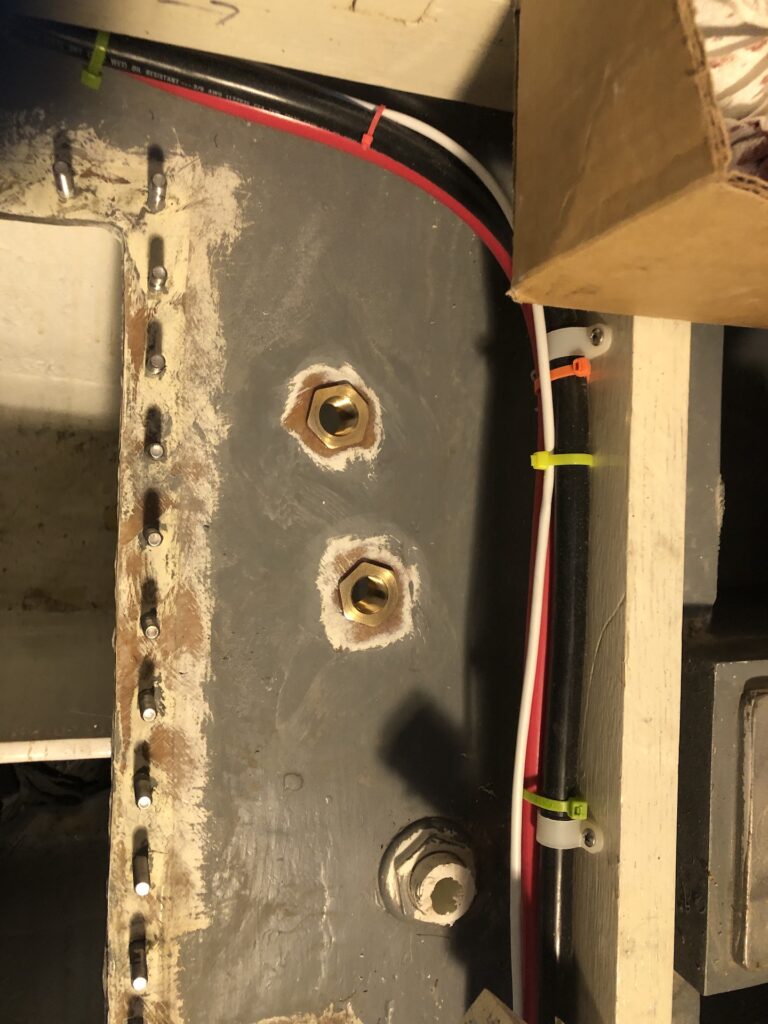
My thinking on the vent and draw ports has evolved and I closed up the originals and installed two brass thru-bulkhead fittings that threaded on the inside (at 1/2 inch NPT). Here are the two on the forward tank:
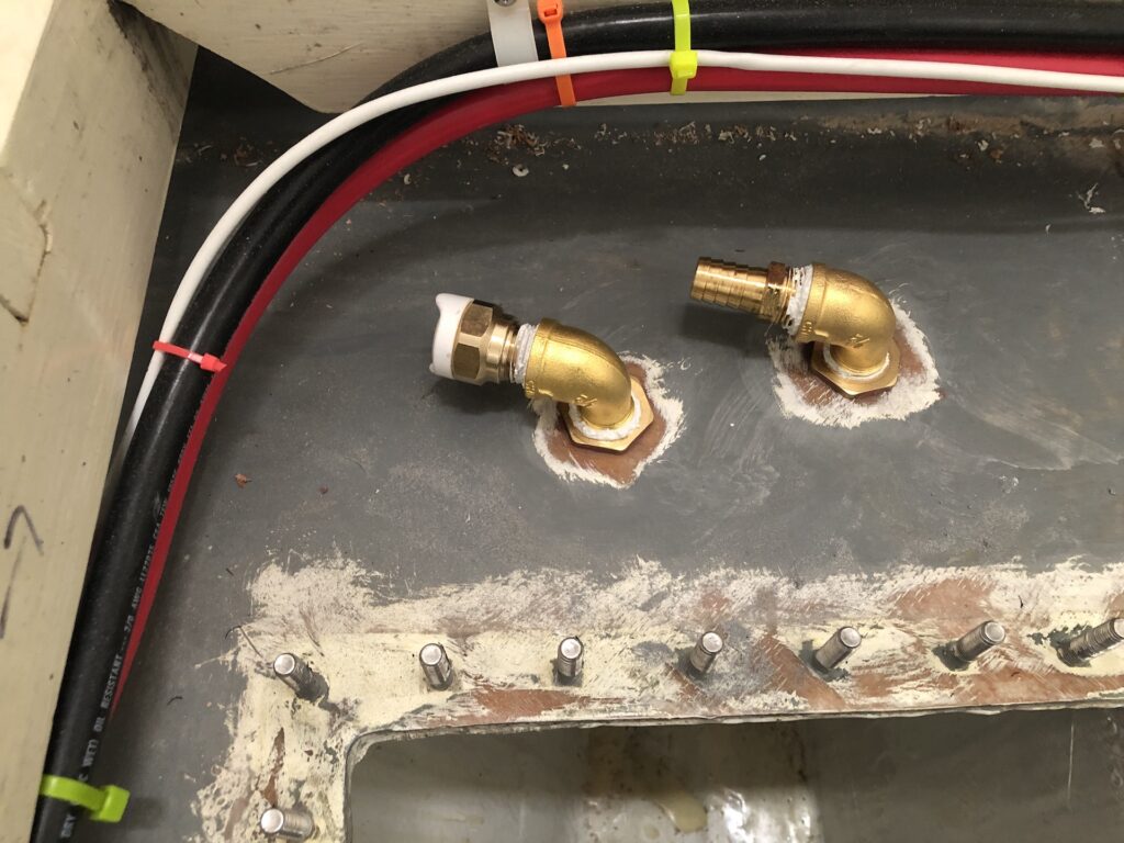
Each vent port accepted a brass elbow and onto the elbow a straight barb. The draw ports accepted a brass elbow and a quick-connect fitting. Here is the forward tank again:
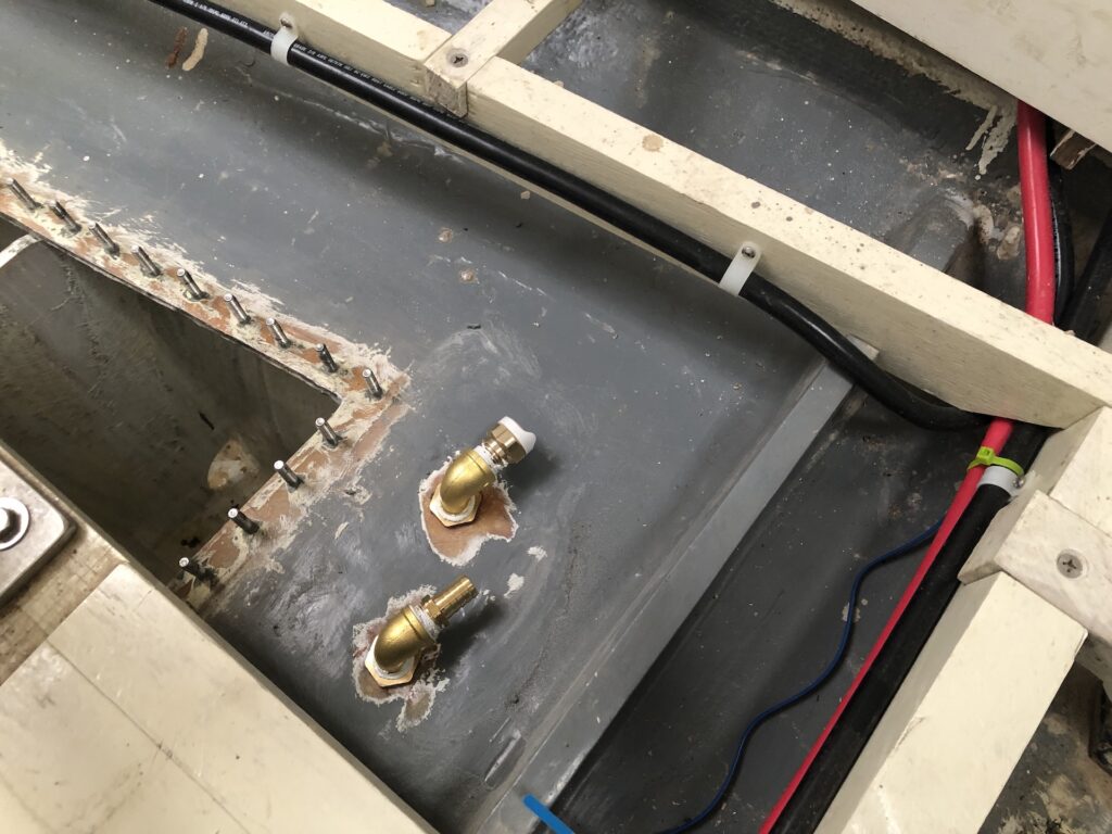
And those on the aft tank:
Obviously the draw ports need draw tubes inside the tank, and those will simply be the Whale hose connected to a quick-connect inside the tank.
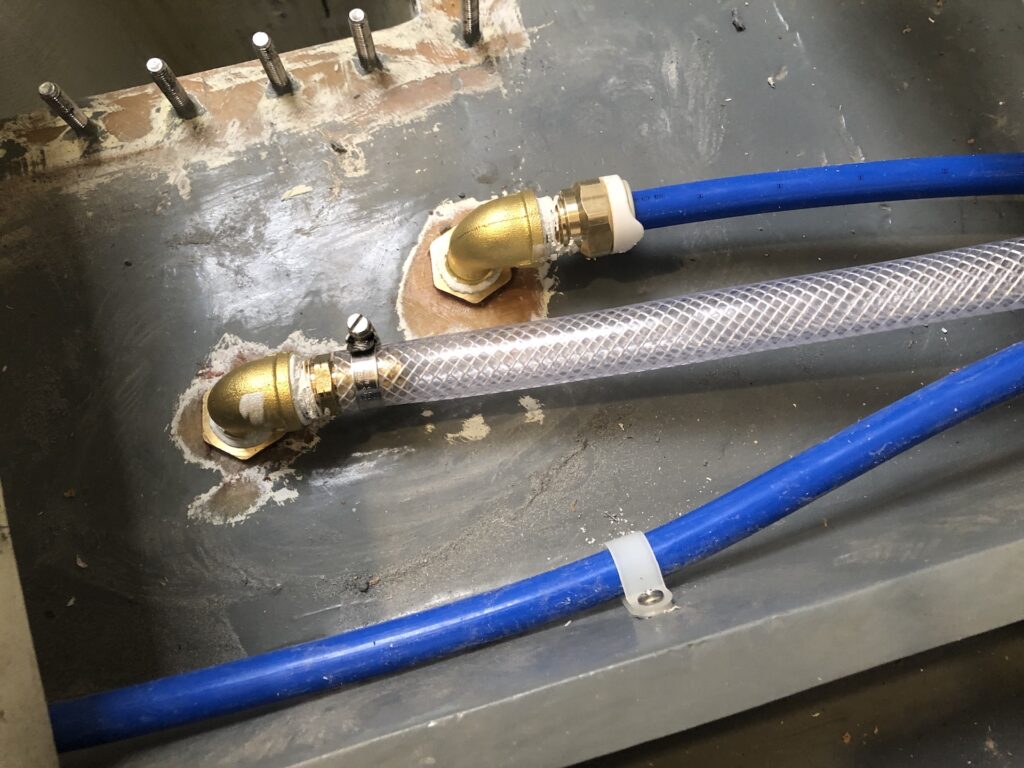
The vent hoses are clear plastic and lead up into the lockers under the berths, and terminate just under the level of the locker covers. I estimate that this will be high enough so tank water will never spill from the vent at any reasonable angle of heel. We’ll see. Aft tank:
Forward tank:
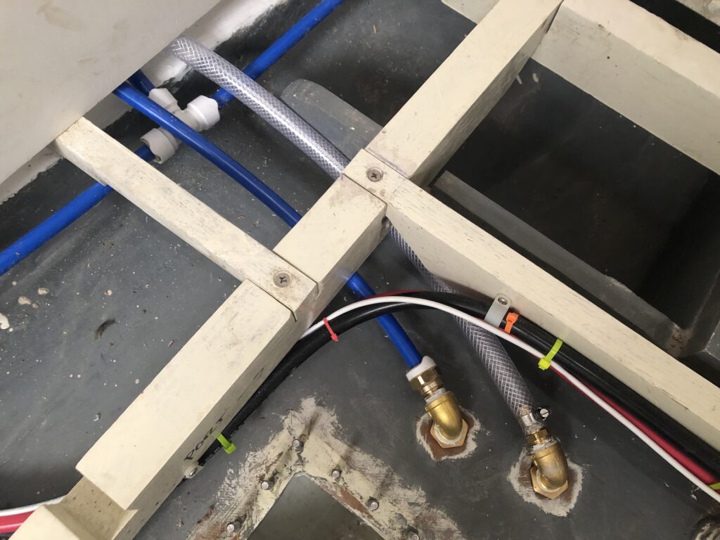
The blue hoses run from the draw ports to the valves you see in the image below. The valves choose from which tank the pump draws. The pump is pretty simple, with one hose in and one out.
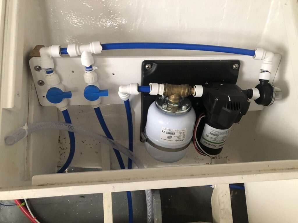
Cold water that leaves the pump has three possible destinations: The head sink, the galley sink, or the hot water heater. More about that next time as I needed to order more hoses and fittings before continuing with this job.
Meanwhile, I began thinking about the hot water heater. It will be installed in the starboard cockpit locker, so I naturally began thinking about the under-cockpit area, which was designed and built, then disassembled last November. (Click HERE to review.) I disassembled the structure to facilitate working on the engine, plumbing, steering, engine controls, rudder, cockpit drains, and so on. That said, this is a good time to put down the forward-most floorboards under the cockpit on both sides of the boat. I retrieved all of the stuff from the cabana, and got to work painting.
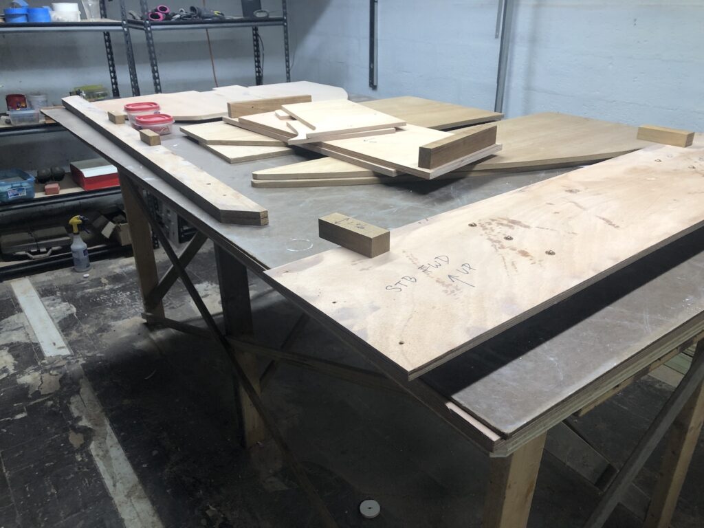
About half of the above fits on the table in painting mode. I’ll chip away at the rest, but one of those in the image below is needed for the hot-water heater.
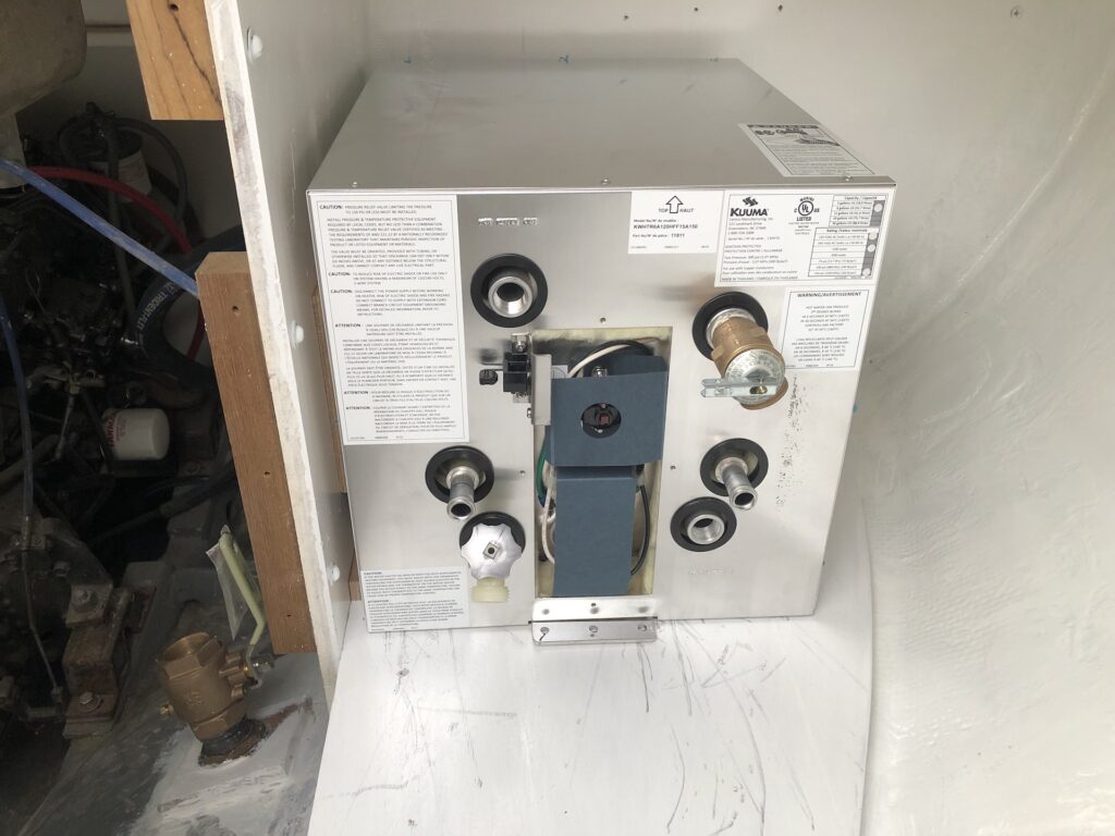
Here the new hot-water heater sits on its floorboard. The floorboard must be screwed to a floor-beam and several cleats, then the water heater is installed. This order of doing things presents a problem.
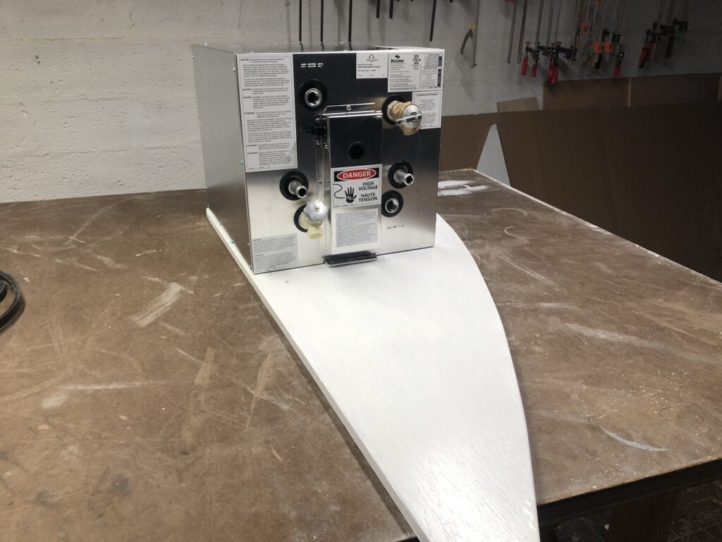
The problem is that the forward end of the tank will be inaccessible when the tank is position, so cannot be screwed down by the flange you see in the image below.
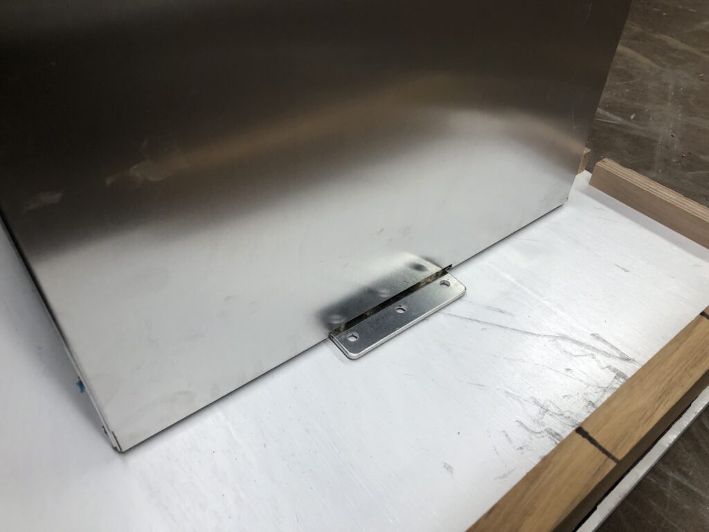
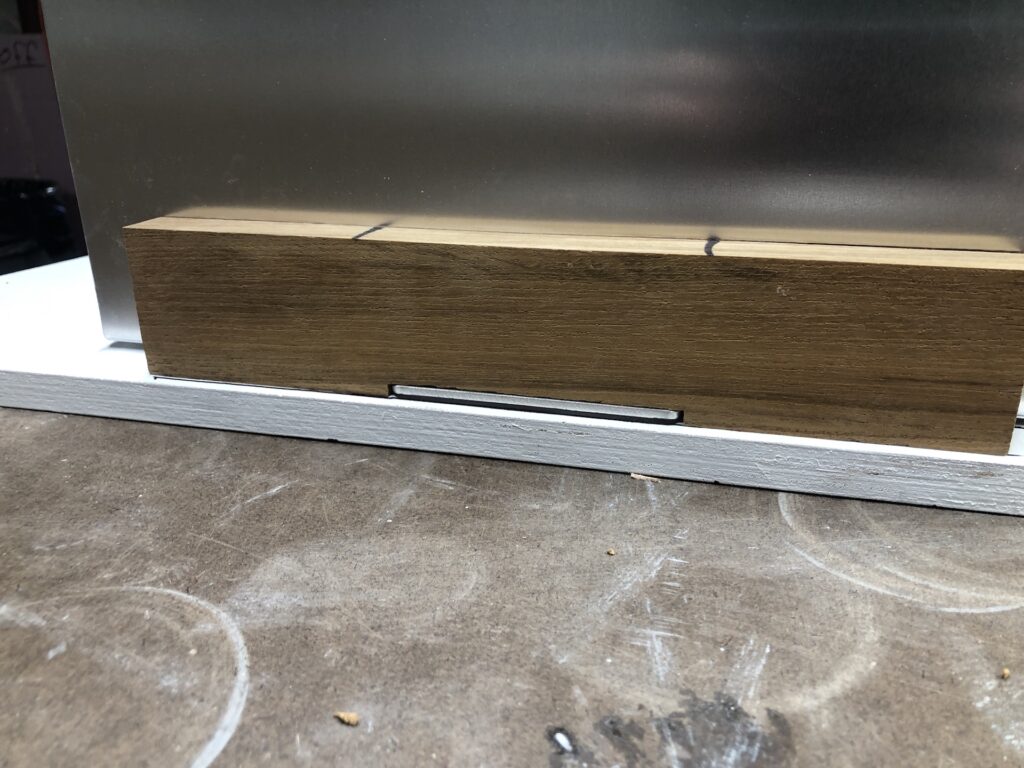
I solved the problem by dadoing a slot in a piece of teak into which the flange on the forward end can slip. Here is a closeup. The teak is screwed to the floorboard and is completely immobile.
Here the floorboard is installed:
Here the water tank is in place. The panel over the electrical area is removed to access the flange on the aft end for bolting down.
When hot water leaves the water heater it has two possible destinations. One is the galley sink. I chose the Ambassador Marine Trinidad Head/Shower Combo Faucet. It has a 6-foot hose, but I might install a longer one for showering in the cockpit.
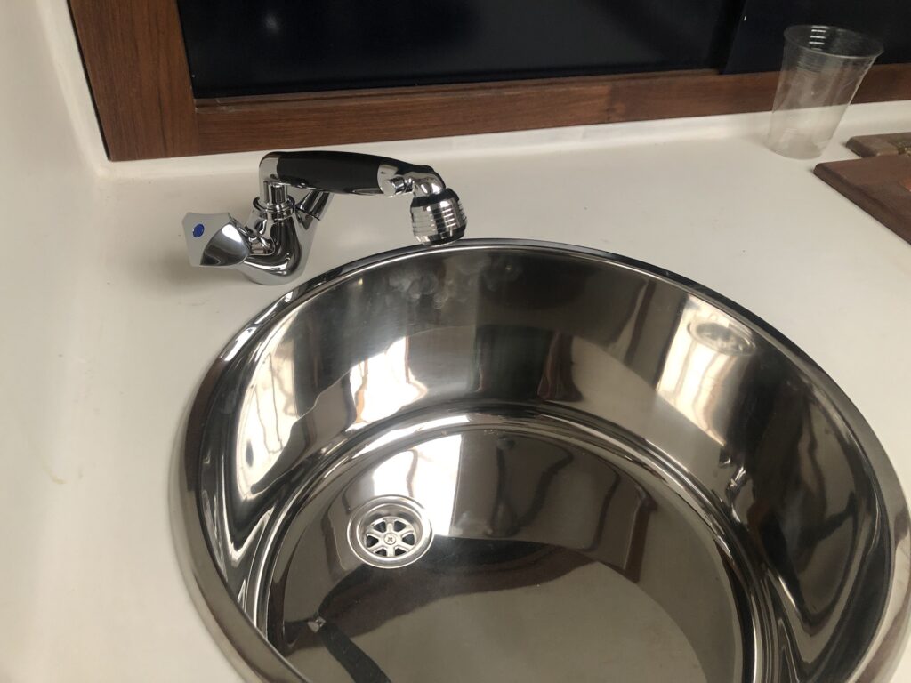
I chose the same faucet for the head sink, which is the second destination for hot water. The sinks and faucets are not yet installed, but should be by next week’s post.
