6/17/23: Engine, Drivetrain, Control Cables, Garboard Drain, Cockpit Drains, Steering Stops
ENGINE
The engine was moved in 2014 (LINK) to make way for restoring the bilge area under the cockpit. Some work was done on the engine bed (LINK), and later that year the engine was moved back onto the bed (LINK). In 2020, my mechanic and I were unable to start the engine, so I had the injection pump and injectors rebuilt. Then we were able to start the engine (LINK).
Fast forward to last week the engine started right up after almost three years:
DRIVETRAIN
The drivetrain on a boat consists of components that begin at the gearbox and terminate at the propellor nut and zinc. On RUCKLE these consist of (1) the shaft coupling that connects the propellor shaft to the engine, (2) the propellor shaft, (3) the shaft seal, which keeps the ocean out, (4) the stern tube, through which the propellor shaft passes, (5) the cutlass bearing, which is at the aft end of the stern tube, (6) the propellor, and (7) the propellor nuts and zinc.
The stern tube is a hollow carbon-fiber tube that is barbed at one end (left in photo below)…
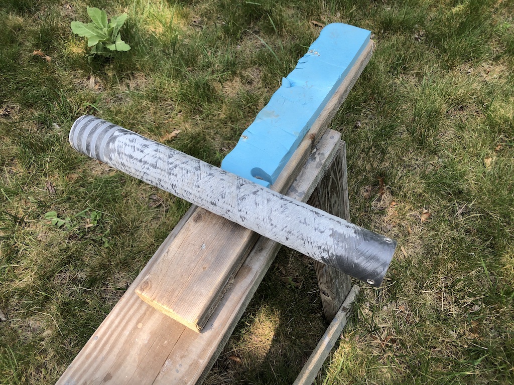
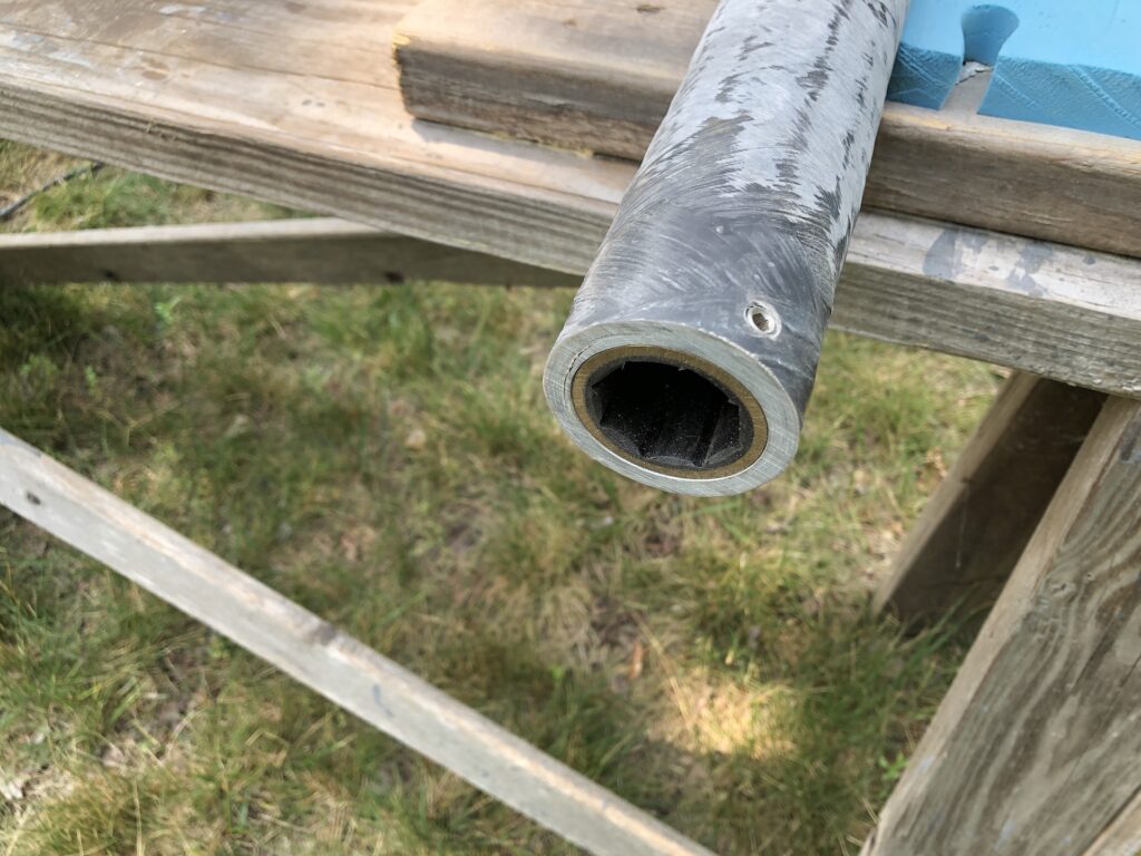
…and houses the cutlass bearing at the other:
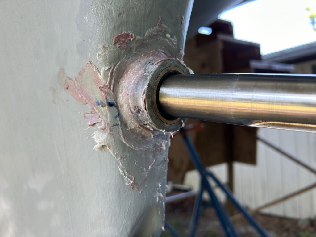
The stern tube must be bedded into the shaft log. (In a wooden boat a shaft log is “A heavy longitudinal timber placed over the keel in a ship’s stern through which the propeller shaft passes“. In my boat it includes a fiberglass exterior.) Here the stern tube experiences a dry fit in the shaft log:
My choice for bedding material was thickened epoxy, and the installation procedure went something like this:
(i) The fit in the shaft log was a little tight, so I removed some material from the exterior of the stern tube to create some play.
(ii) I decided to install from the inside out, so I taped off everything you see in the image above.
(iii) The shaft log is about 12-14 inches long, and I slathered the inside surface with thickened epoxy using a slender piece of plywood.
(iv) I slathered the appropriate areas of the outside of the stern tube with thickened epoxy.
(v) While a helper inserted the stern tube into the shaft log (very slowly) from inside the boat, I monitored progress from the outside, and scraped off the inevitable squeeze out.
(vi) When the aft end of the tube was in the correct position, I injected epoxy thickened with high-density filler into the gaps in the aft end.
(vii) I inserted the propellor shaft and swapped places with my helper. Inside the boat I attached the coupling to the shaft and the gearbox. In this way, the epoxy would cure with the cutlass bearing and, thus, stern tube aligned with the shaft.
(viii) Finally I cleaned up the squeeze out on the inside and and made epoxy fillets on both ends where the tube enters the shaft log.
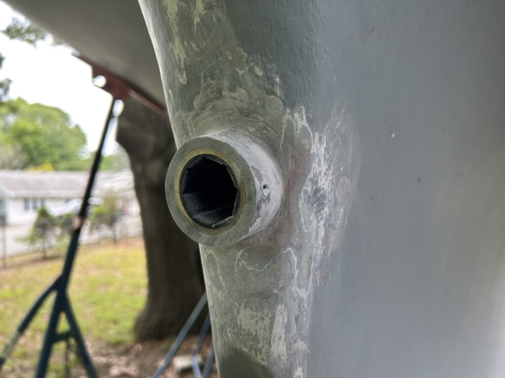
I would have liked some pictures of this process, but the epoxy “kicking” before I had finished would have been a very serious setback. The best I was able to do is take an after photo:
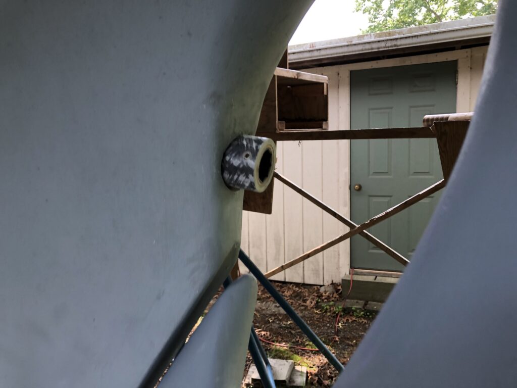
Here, 24 hours later, I’ve cleaned up on the inside and outside. Here’s the outside:
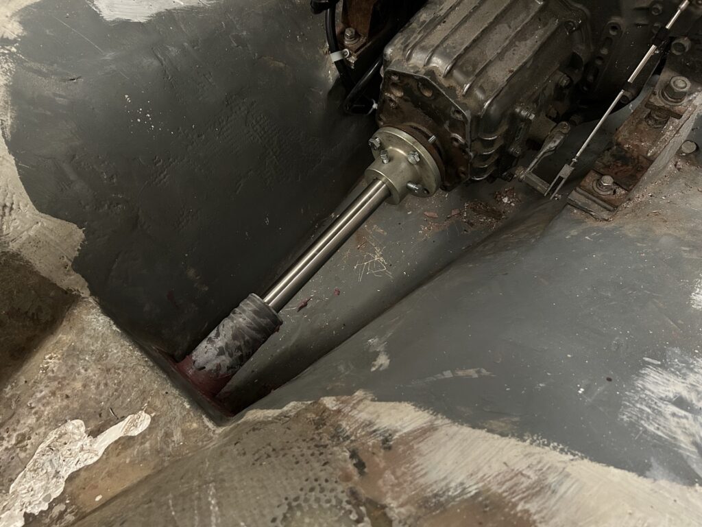
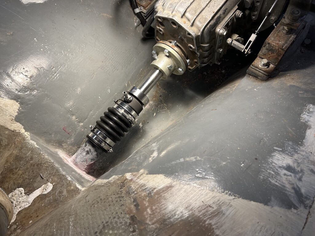
The shaft enters through the cutlass bearing…
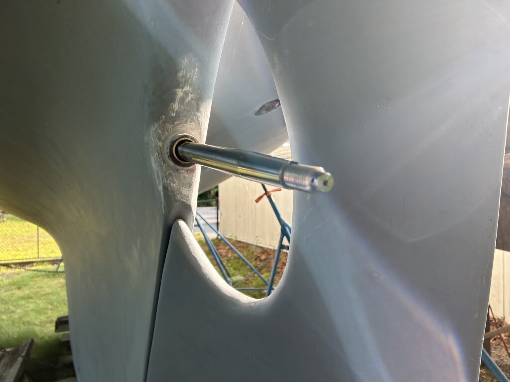
…and the shaft seal must be assembled before coupling the shaft to the engine.
I chose, upon recommendation from my mechanic, a dripless shaft seal (LINK to product page). Instead of a traditional packing gland, this seal keeps the water out by seating a carbon flange against a stainless-steel rotor. The advantages of this system is that it is 100% watertight, has a long maintenance cycle (six years), and produces no wear on the shaft.
Here the stainless rotor is installed:
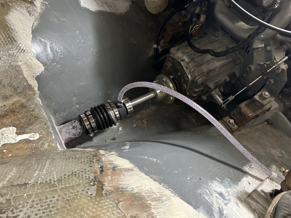
We moved the motor around a bit on its mounts until we had near-perfect alignment of the shaft coupling and motor, then tightened all the bolts.
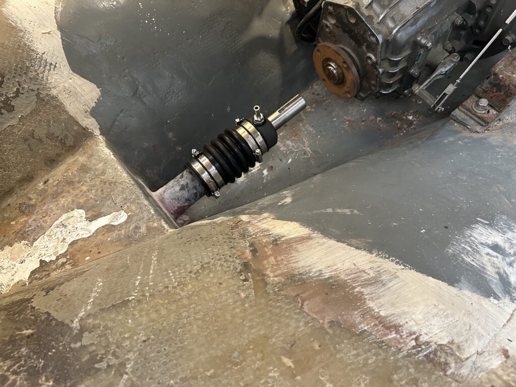
Water enters the stern tube through the cutlass bearing, and the shaft seal is vented via the clear tube you see here:
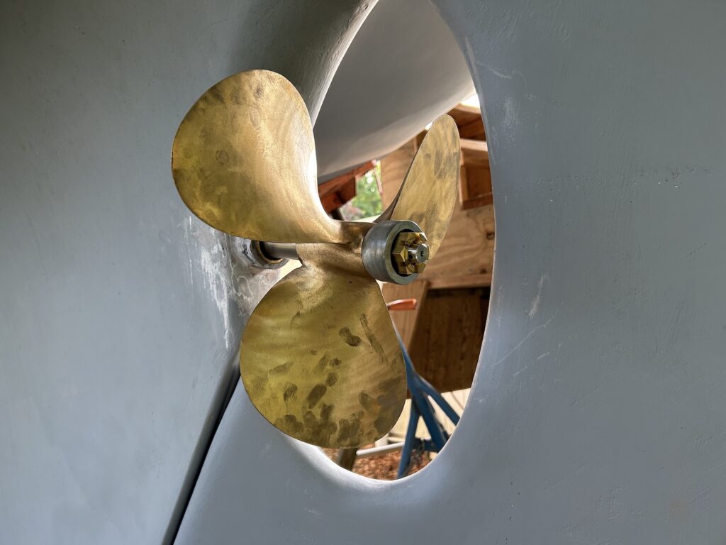
The propellor was installed, complete with its zinc:
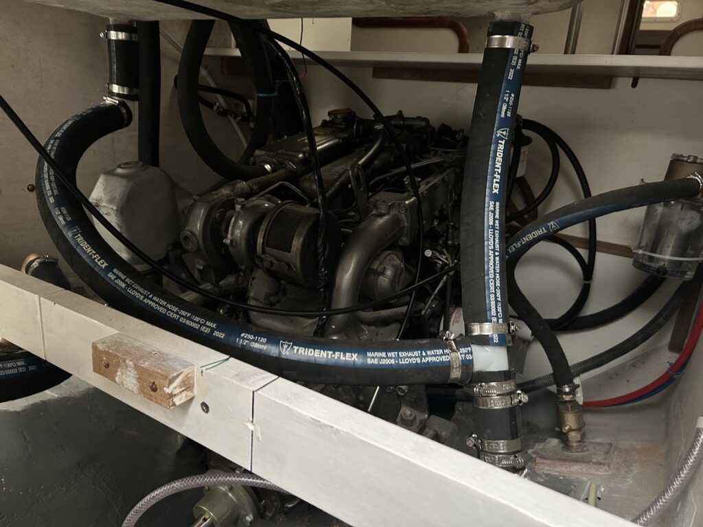
SHIFT AND THROTTLE CABLES
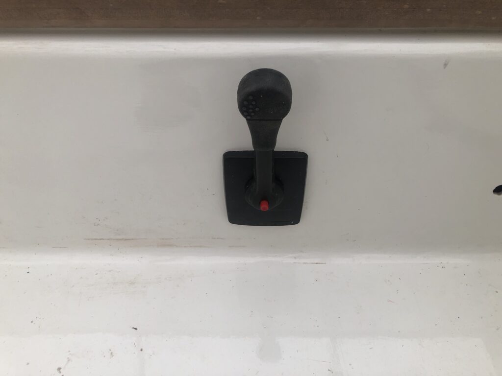
I installed the shifter a few weeks ago:
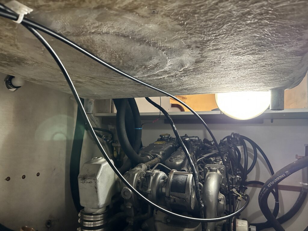
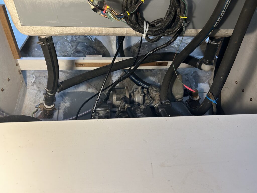
This week I installed the control cables. One for throttle, and one for forward/neutral/reverse. They run from the shift…
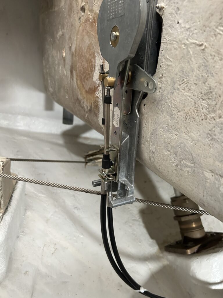
…under the cockpit…
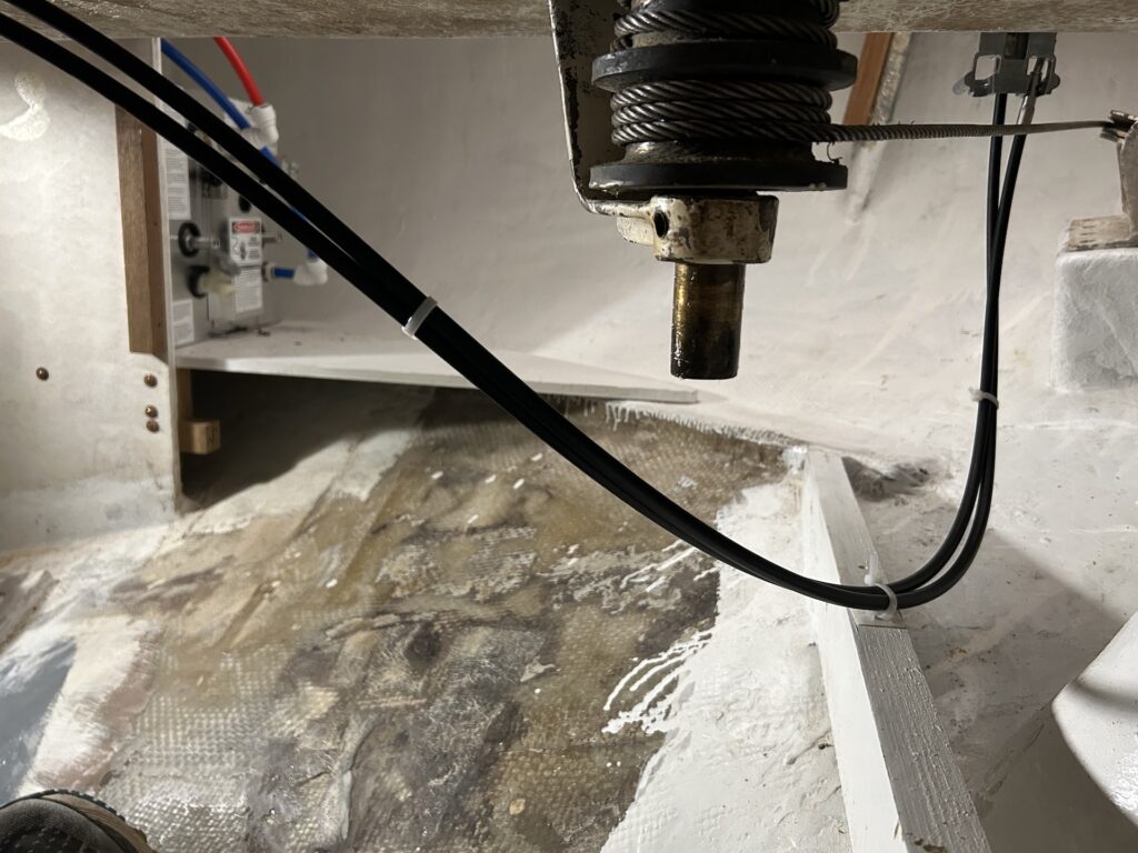
…and forward to the engine:
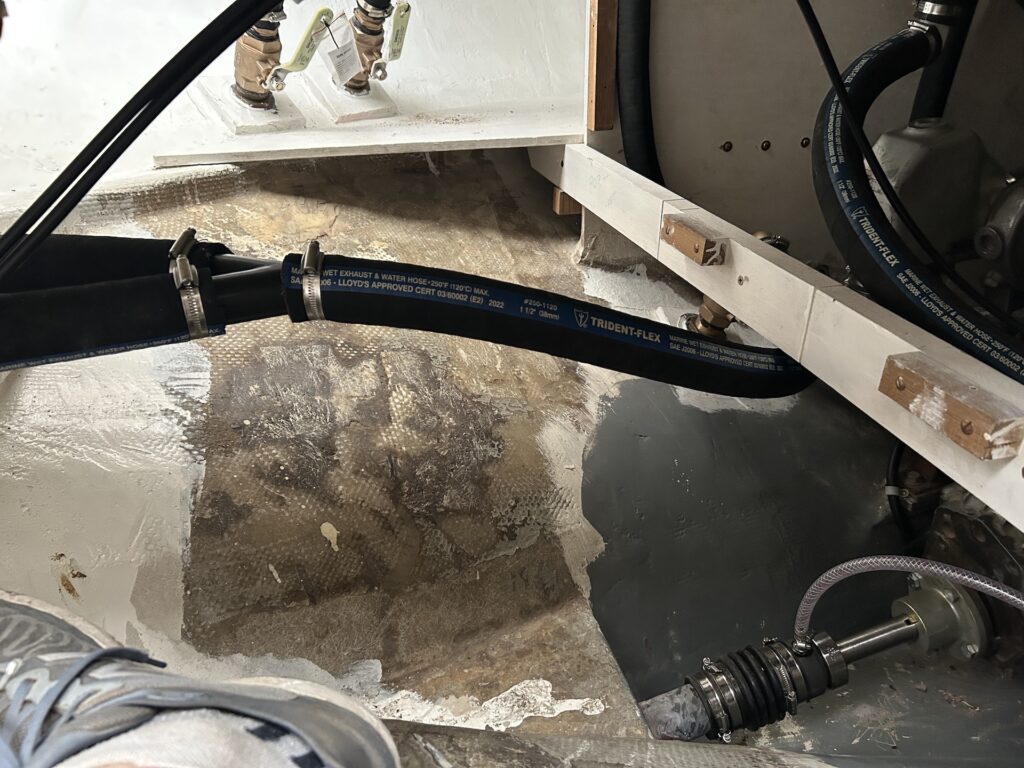
GARBOARD DRAIN
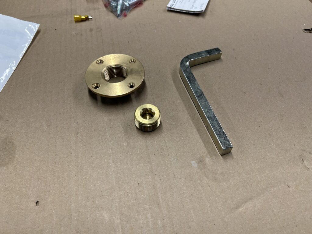
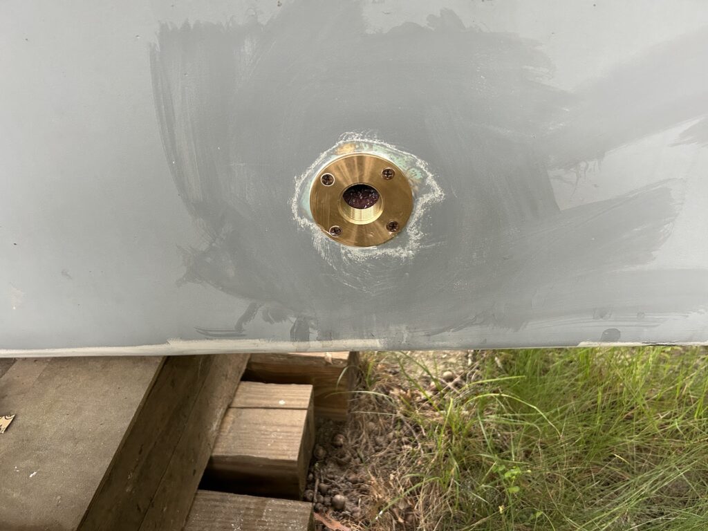
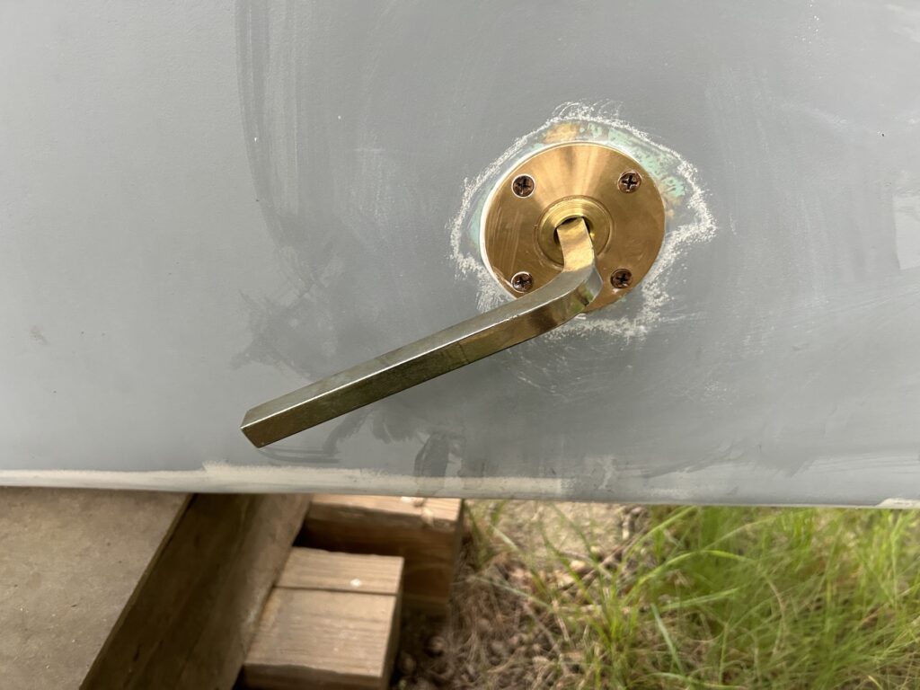
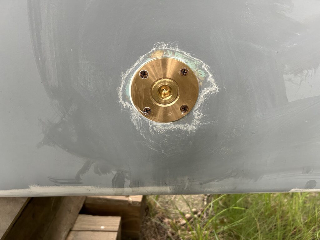
The garboard drain is on the side of the keel and installed at the very bottom of the bilge. It is opened when the boat is out of the water and allows bilge water to drain to the ground. This is convenient for cleaning the bilge, but also prevents the situation of frozen water in the bilge in the winter months. I purchased a new drain plug…
…and installed it:
COCKPIT DRAINS
There are four cockpit drains–two at the aft end, and two forward. I installed the thru-cockpit-sole end in 2019 (HERE), and the thru-hulls more recently (HERE). Finally I’m at the point where plumbing them makes sense. I T’ed together the two at the forward end and led them out the starboard-side thru-hull:
I Y’ed together the aft two and led them out the port-side thru-hull:
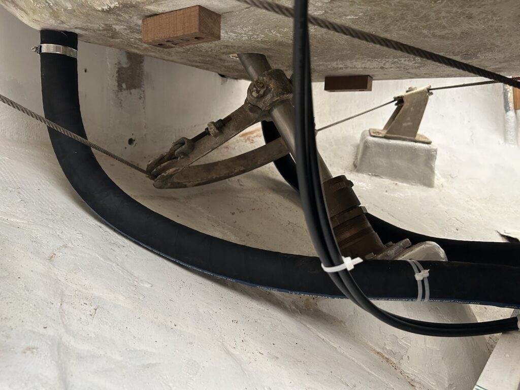
STEERING STOPS
Two images above you can see two teak blocks I screwed into the underside of the cockpit sole. These stop the quadrant turning further than it should, and in thus sets the maximum angles that the rudder can make.