5/21/23: Stove, Propane System, Stern Light, Mizzen Pad Eyes
STOVE
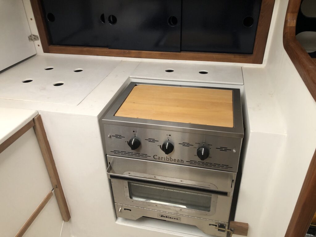
After a 2017 purchase, the oven/stove finally met the boat:
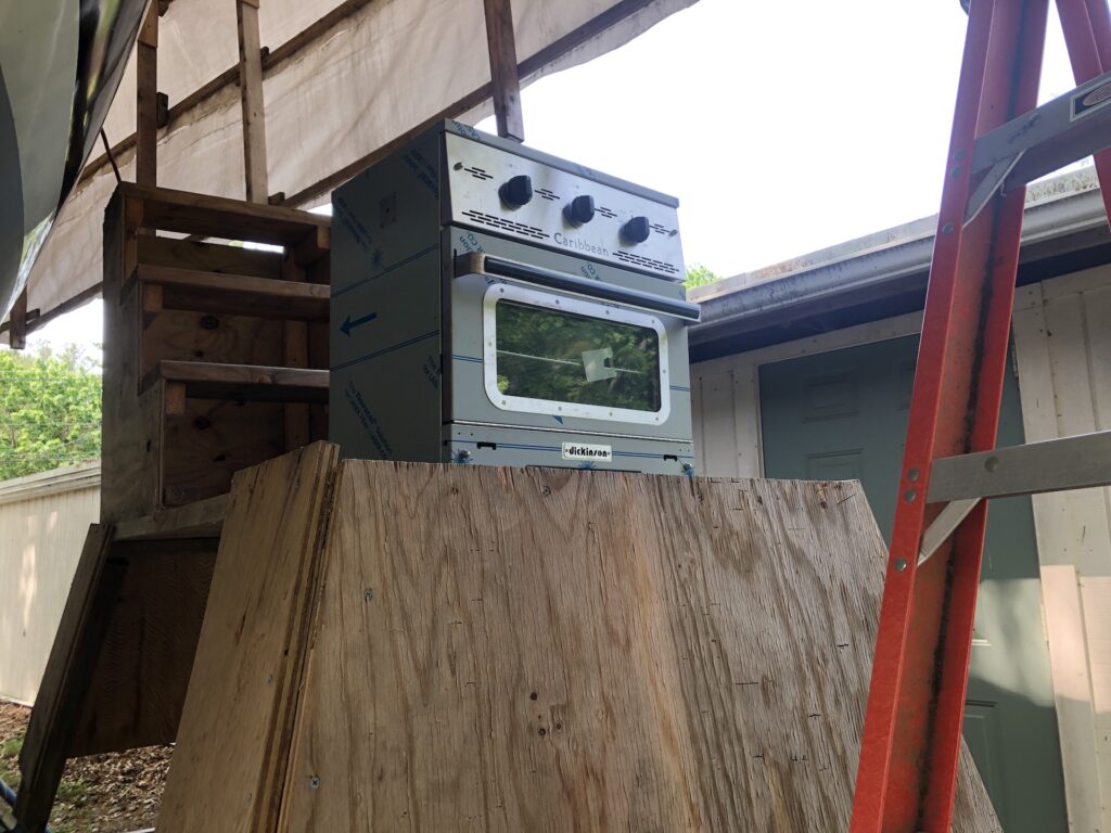
I chose the gimbaling option, not only for the gimbaling option, but for easy removal for cleaning around and under the stove. Long ago I planned out the location of the mounting brackets, and I trusted those old measurements.
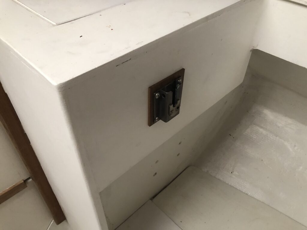
On the lower right is a barrel-bolt that, when engaged, prevents gimbaling. I expect to rarely use the stove when underway, but the option to gimbal will sometimes be useful.
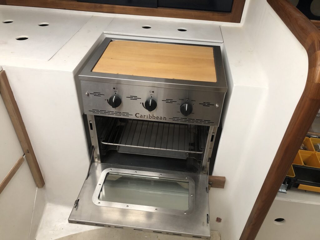
Here the oven is open:
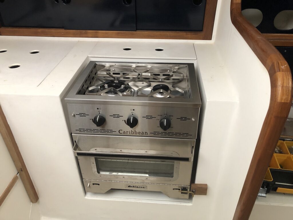
Here the cutting board is removed to expose the two-burner cooktop:
PROPANE SYSTEM
A propane stove requires a propane fuel source, which originates from a propane cylinder in a so-called “propane locker.” From HERE, we have:
…cylinders should be contained in an approved storage locker. Any locker must be above the normal level waterline of the boat, it should drain any leaking gas to atmosphere, and it must not allow any escape of gas to find its way into the interior of the boat. The gas locker should be used for the sole purpose of storing gas cylinders and no other equipment.
ABYC also specifies that the locker be constructed, or lined, with corrosion-resistant materials. Fiberglass is an almost perfect material for any such locker. Additionally, any gas locker must only be able to be opened from the top and have a latch so that it can be properly sealed closed, although the latch should not require tools to be opened. Finally, because propane is heavier than air, any locker must have a drain at its lowest point that leads over the side so that leaked gas is safely vented away.
There is a rule of thumb that you will need 1 pound of propane per person, per week of full-time living aboard. This assumes most cooking is done with propane and propane is used for nothing else. Eventually, I’ll install a propane bulkhead heater (like THIS one), which will use about 0.25 pounds per hour.
The locker must be installed either on deck or in a compartment that opens to the outside. On deck is a aesthetically unattractive option, and the only compartment that makes sense is that under the aft deck.
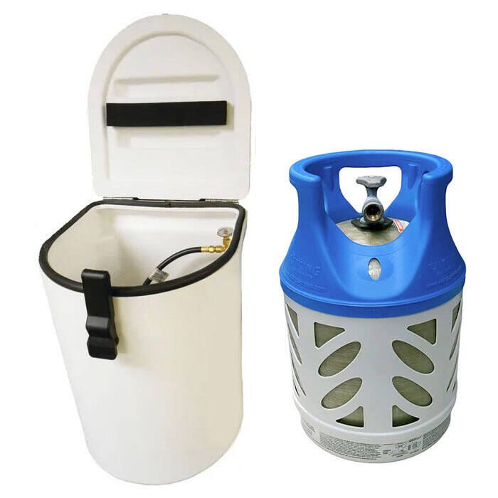
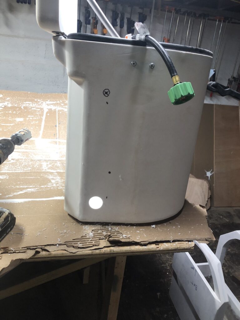
I settled on THIS setup (pictured below), which includes a 17-pound capacity cylinder.
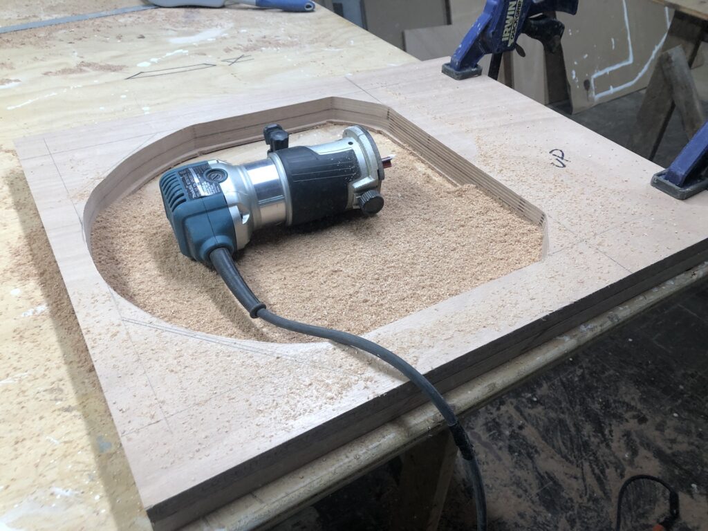
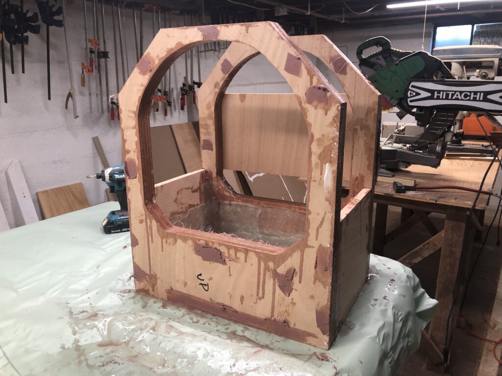
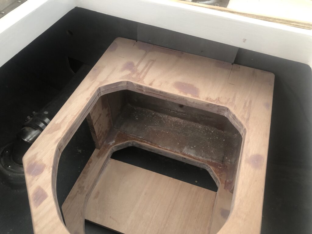
Securing it under the aft deck was a chore. I began by tracing the horizontal cross section to some plywood and making a template with which I made four panels with a cutout:
With these panels, and a fifth for the bottom, and a few more for the sides, I experimented with a few dry fits:
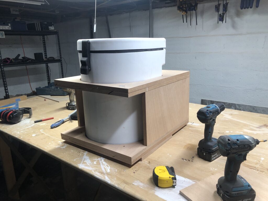
I assembled everything with screws, then did a test fit on the boat. After a few iterations of testing and making adjustments, the contraption looked like this:
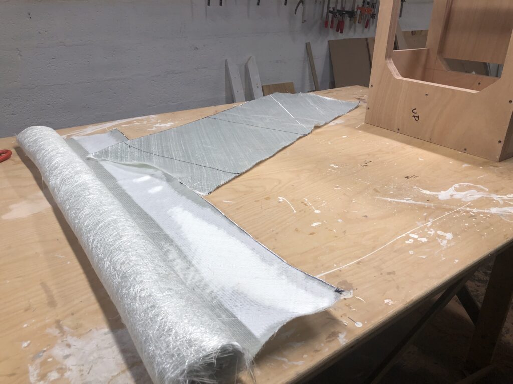
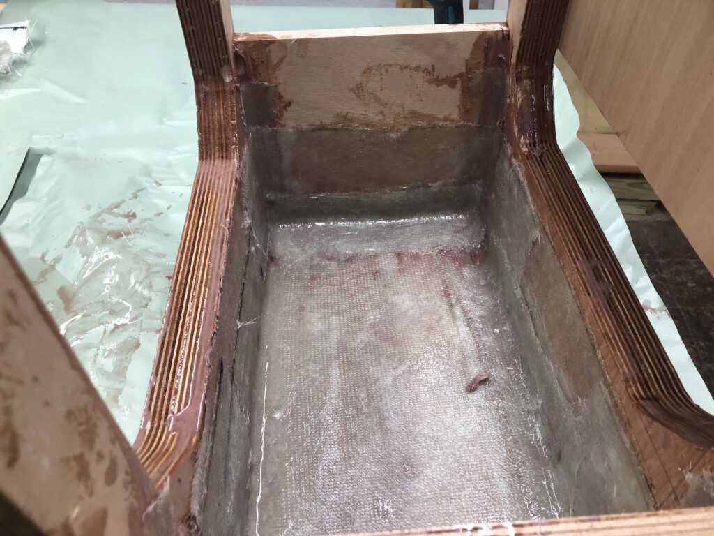
Back in the basement, I prepared to epoxy all the joints and glass the inside of the forward end of the box.
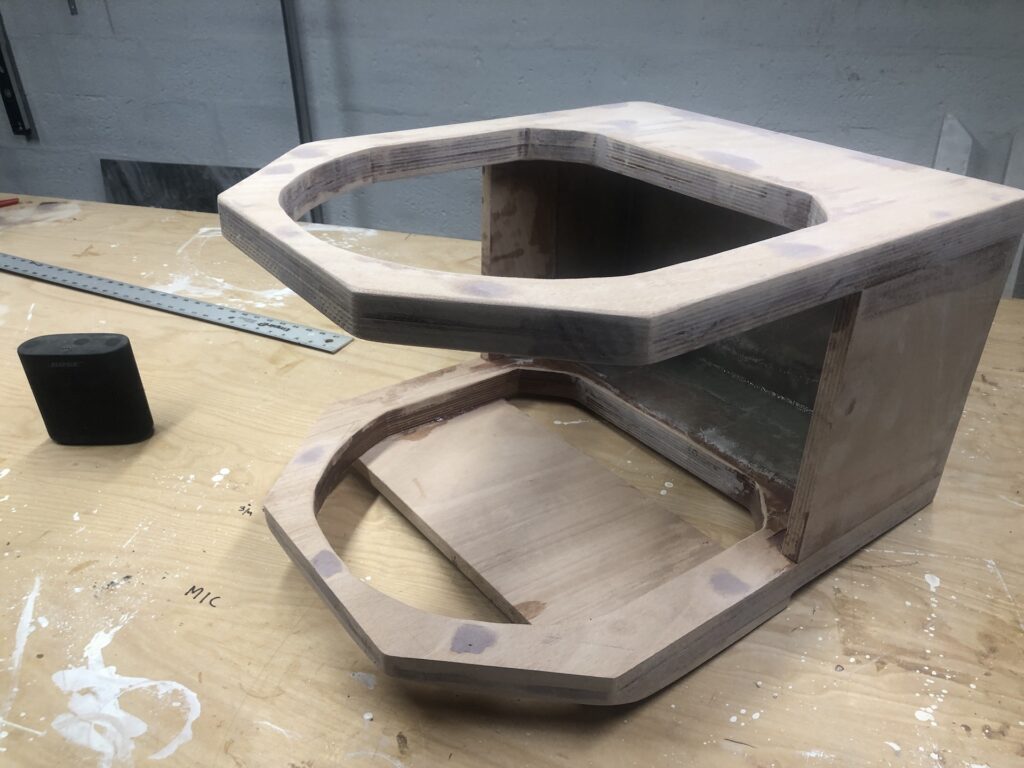
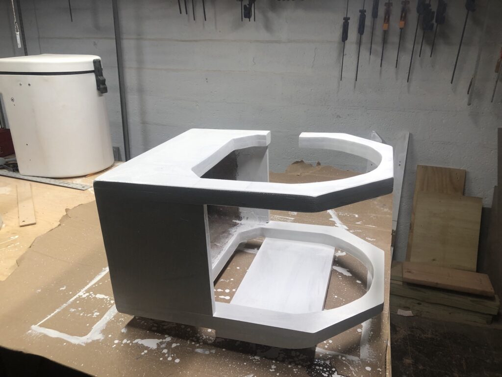
We’ll call this the “locker support” and here it has taken on it’s final shape and is sanded:
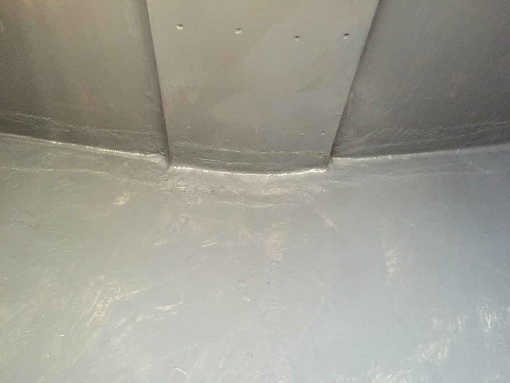
In its original built, the boat had a thin plywood bulkhead under the mizzen mast, which was insufficient as a support for the mast, and had bowed badly. In my rebuild, I installed not only a heavier bulkhead, but a multi-layer buildup just under the mizzen mast. The following two photos are from 2016 (and yes, I drilled a limber hole at some point after these photos were taken):
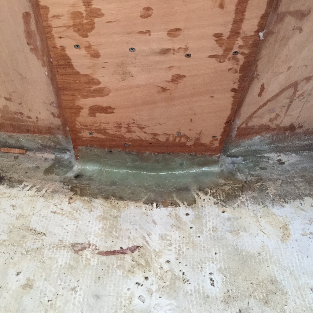
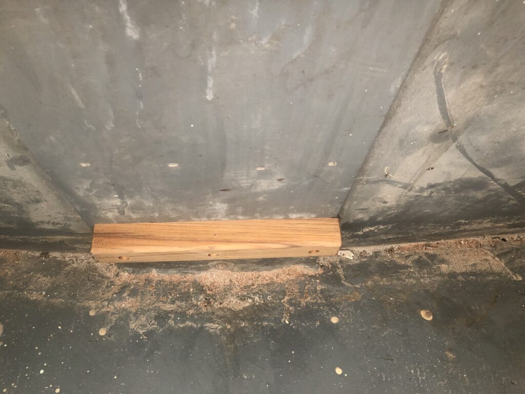
The locker support will be bolted to the strong center section and be raised above the hull. I installed a teak cleat to not only take the weight of the support, as a means to more easily find the correct alignment with the bolt holes.
Here it is bolted to the bulkhead with three bronze lag bolts:
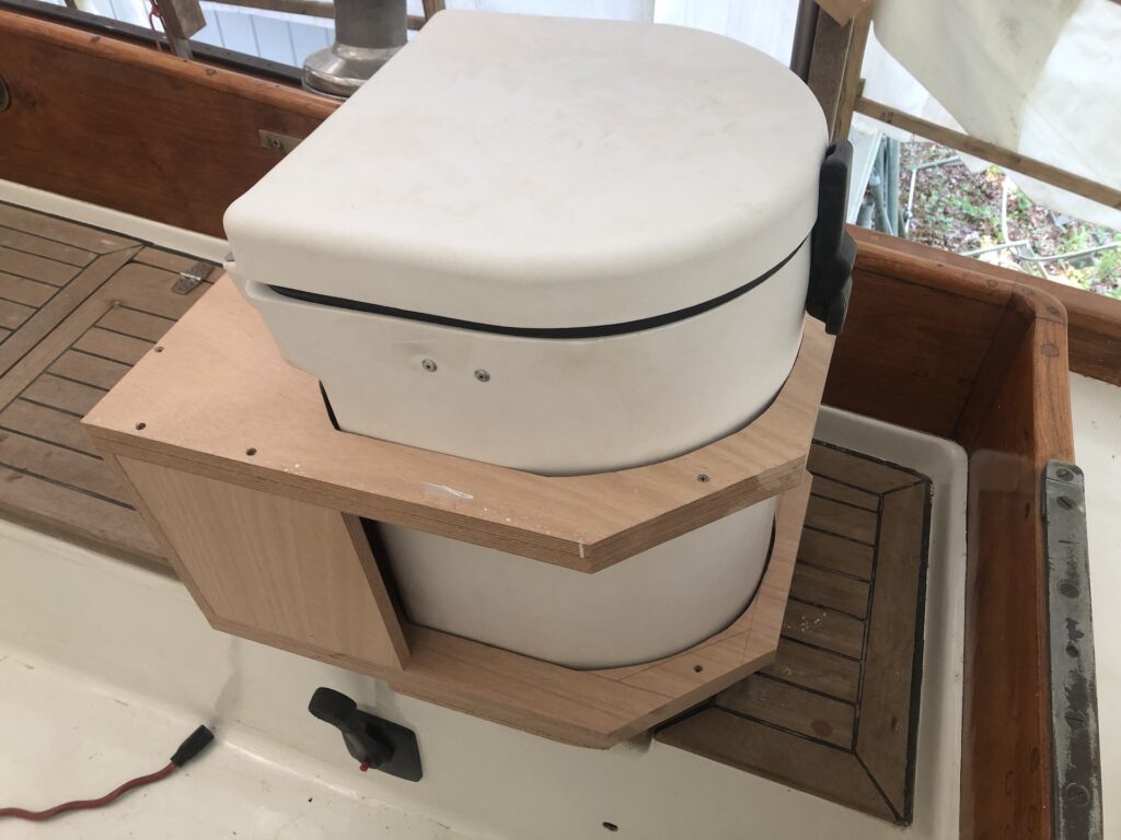
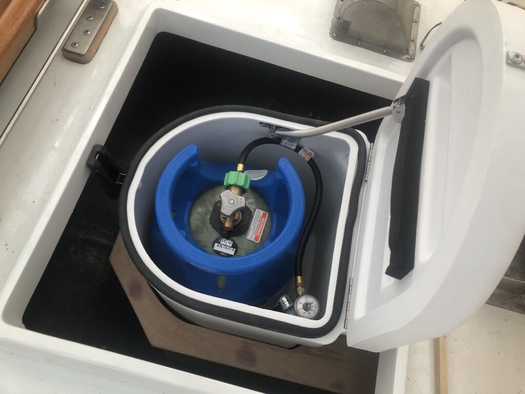
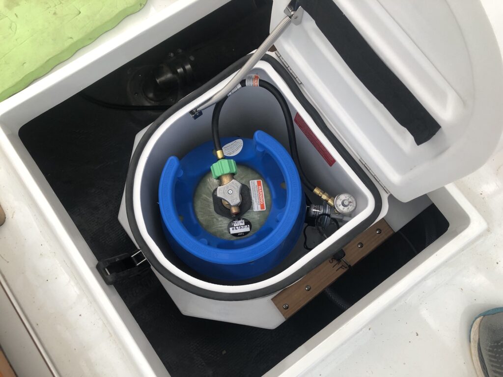
Here the propane locker, with tank, sits in the support.
Back in the basement, for a coat of primer. Notice the gap I cut in the top ring, which is to allow the vent thru-fitting to pass when removing the locker from the support. The gap will be closed with a screwed-in piece of teak that you might notice in some of pictures that follow.
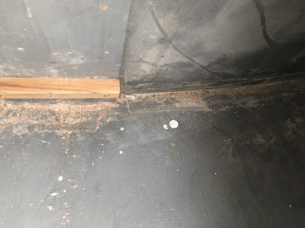
Requirements dictate that the locker must be installed above the waterline, and my plan satisfies that requirement. The vent tube connection on the locker must be above the vent thru-hull, which must also be above the waterline. Here I’ve bored the hole for the vent thru-hull:
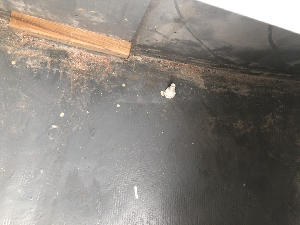
Installed:
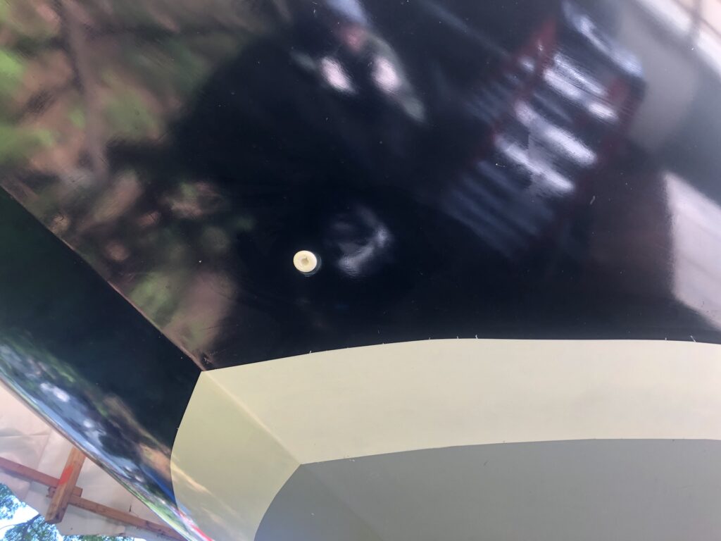
From the outside, the thru-hull is in an inconspicuous location under the transom:
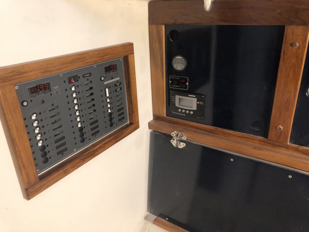
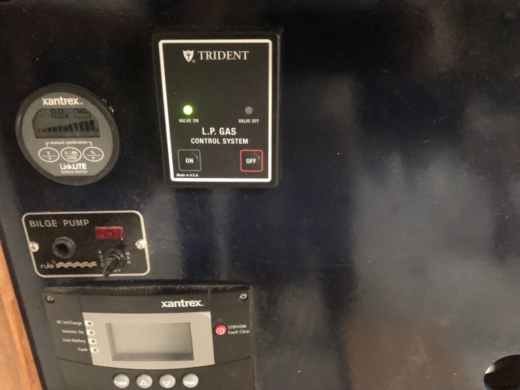
There is a solenoid valve in the propane locker that is controlled by a panel. It’s supposed to live not far from the stove and also not be hidden. I chose to mount it in the face-frame panel you see in the image below, which already contains the inverter controls, a battery monitor, and bilge-pump switch:
Four wires come out of the back of the TRIDENT unit: two make a short run forward to the electrical panel, while the other two make a longer run aft to the locker.
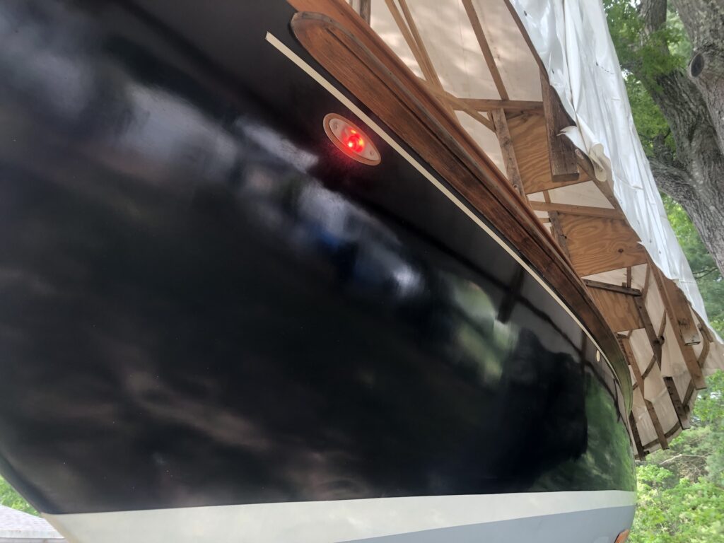
Here the panel is installed and the red light doesn’t mean anything at this point because the solenoid valve isn’t wired yet.
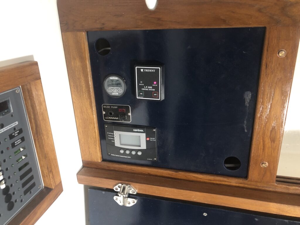
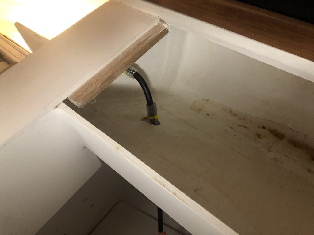
It has two buttons, “on” and “off”, which open and close the solenoid valve. A switch on the electrical panel energizes the TRIDENT device and that switch will be labeled “propane.” Before making the electrical connections to the locker, I needed to run the propane hose. One end terminate behind the stove (removed in this image):
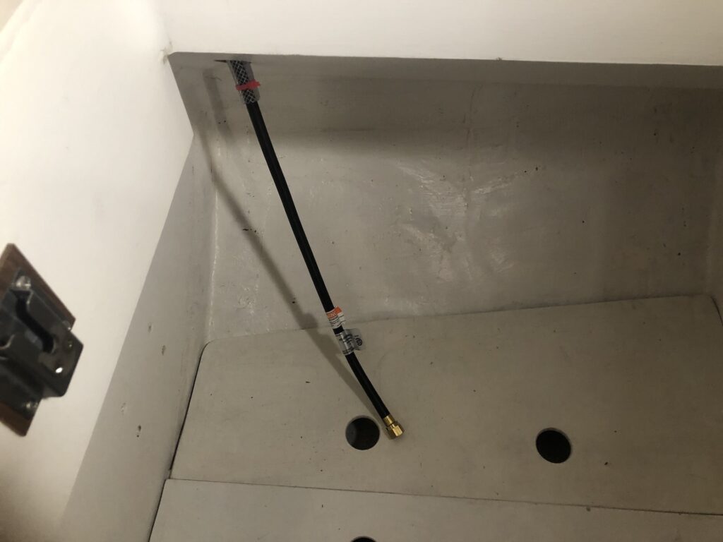
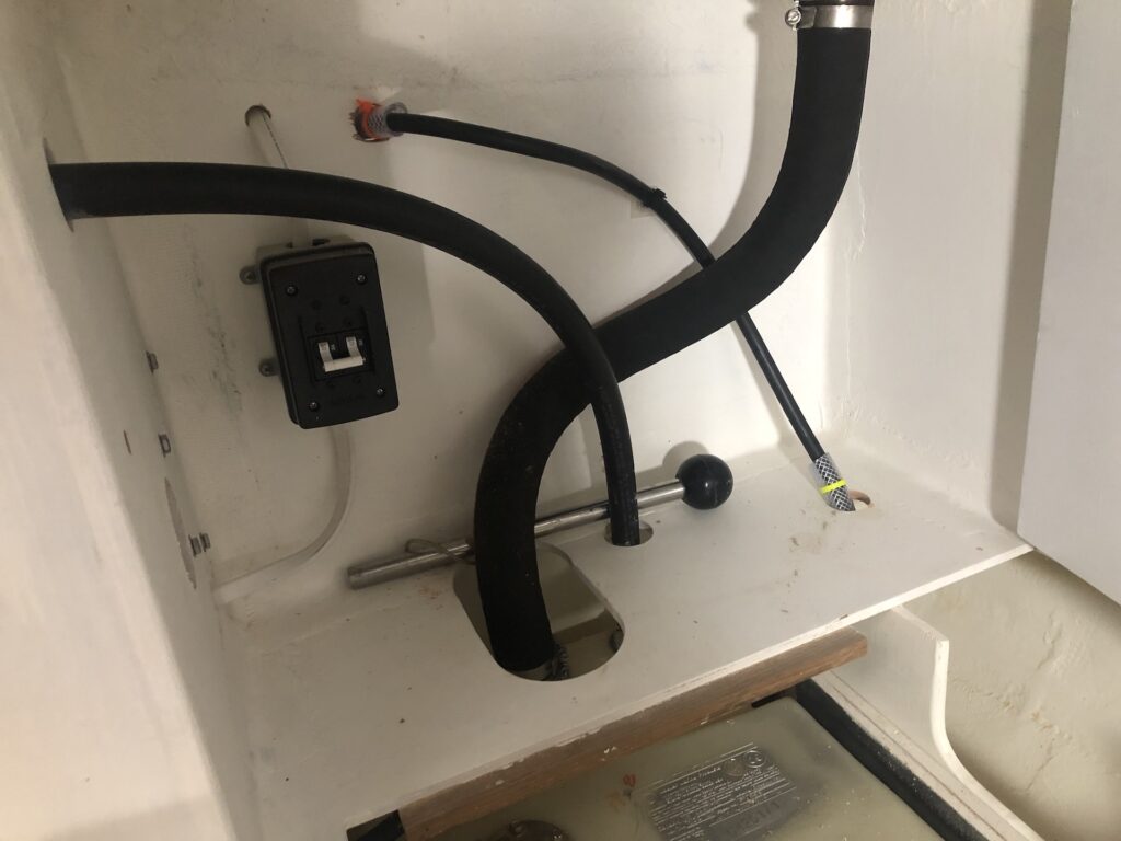
The 20-foot hose runs through various compartments until it reaches the locker under the aft deck. Anti-chafing measures where the hose passes though holes is mandatory:
There are three thru-locker fittings. One is for the vent, one for the electrical wiring, one for the propane line. The end-user is responsible for their installation, which allowed me to choose that the vent and wiring would be to starboard and the propane line would be to port. Here I’ve bored a hole for the vent thru-fitting:
Here the locker is installed and the full propane tank is connected.
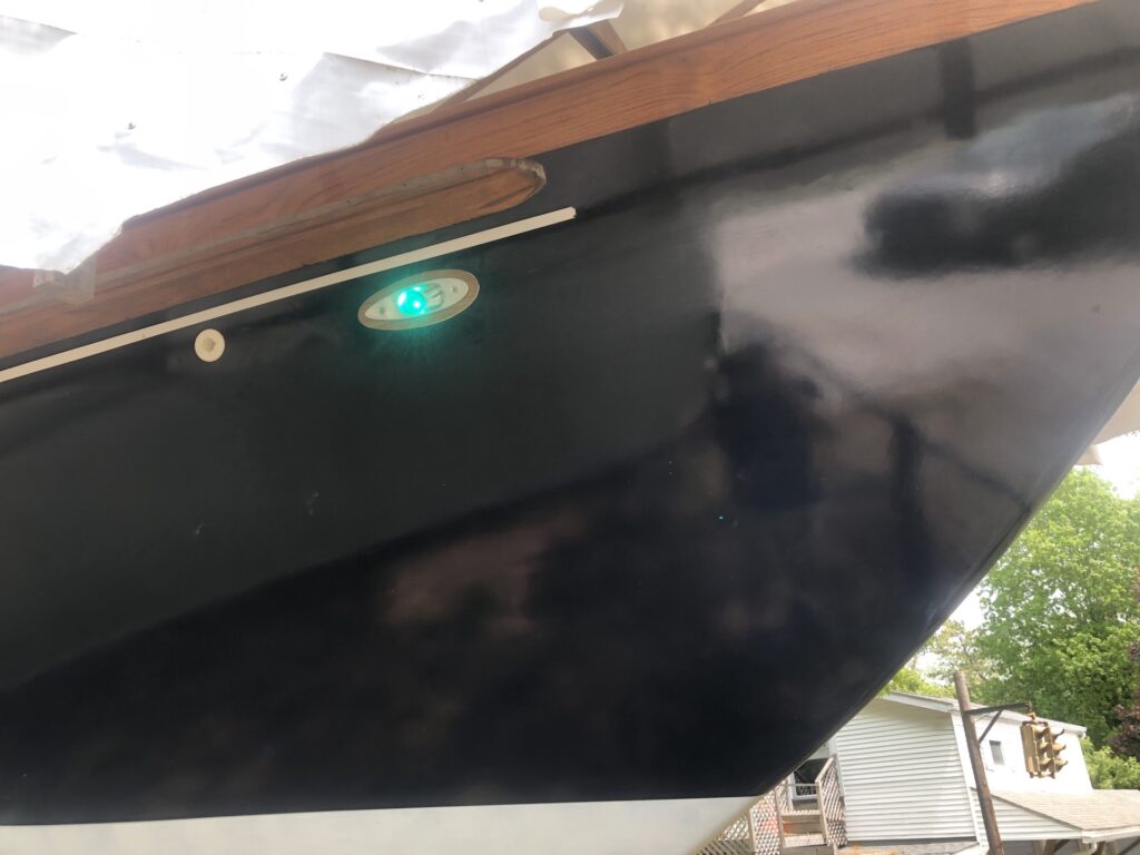
The solenoid valve is wired, and pushing “on” opens it and the panel indicates success with the green light.
Finally time for a few tests:
The small burner and the oven were tested too.
STERN LIGHT
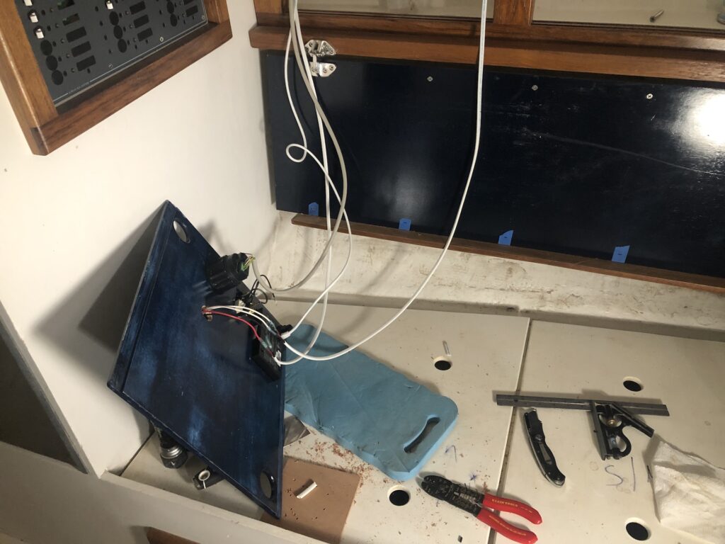
The “nav lights” consist of port (red) and starboard (green) bow lights and a white stern light. Last week’s post detailed the bow-light installation and wiring. The stern light is pictured below. I decided to install it above the transom on the wide cap rail. I didn’t want to attach it directly to the cap rail, for several reasons, so I make a teak block on which to mount it.
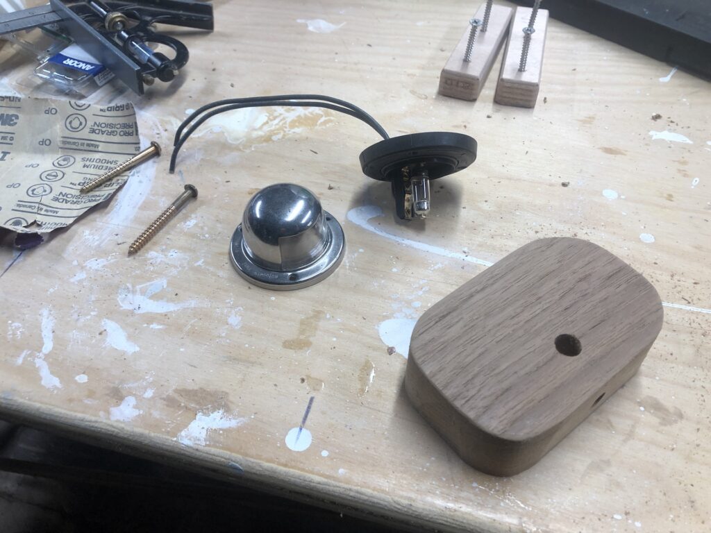
I drilled holes for the wires and screws…
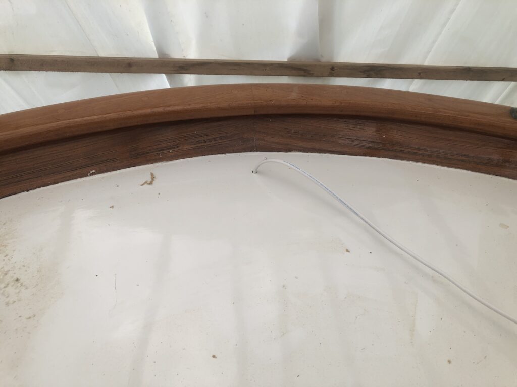
I ran boat wire aft to the stern. (Incidentally, while I’m not showing you much of the wire runs, they are neatly run and mainly run along the under-deck surface, attached with wire clips.) This wire run came up through a hole I drilled in the aft deck:
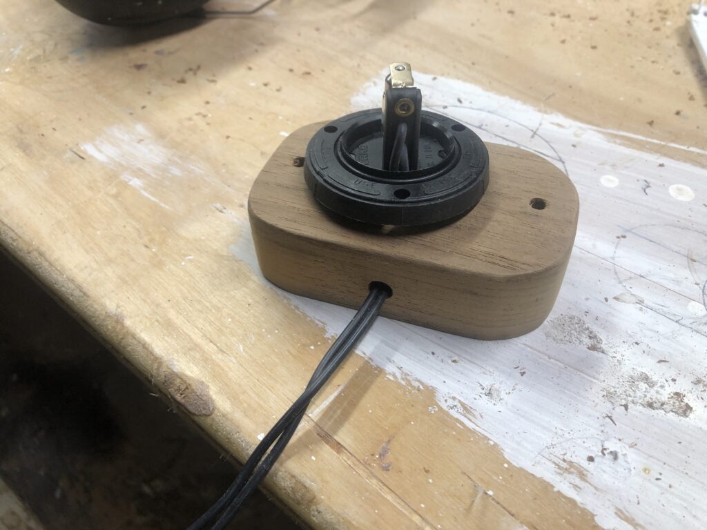
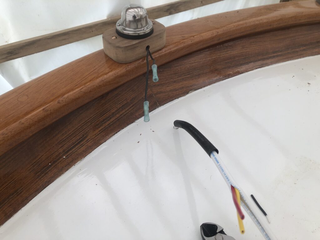
Here I’ve screwed the base to the cap rail, and the light to the base, and have begun wiring the connectors. A 6-inch length of heat-shrink tubing covers part of the boat wire. The connectors are the heat-shrink type, too, whereby applying heat with a heat gun shrinks the plastic, making a tight seal around the wires.
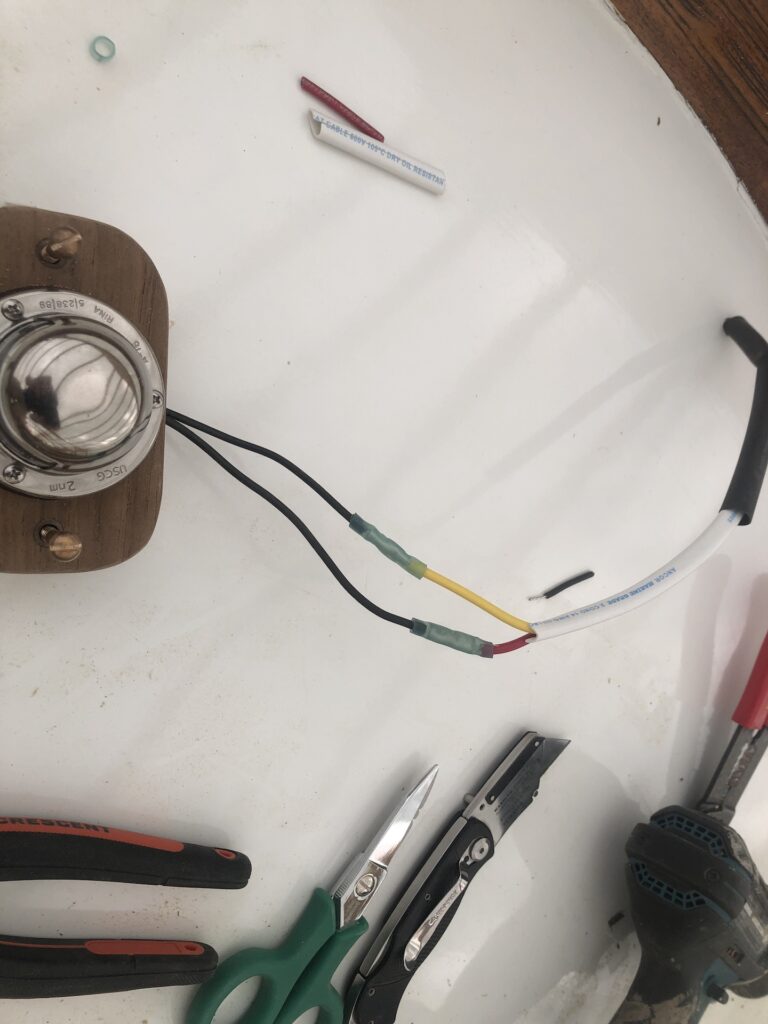
Here I’ve heat-shrunk the connectors:
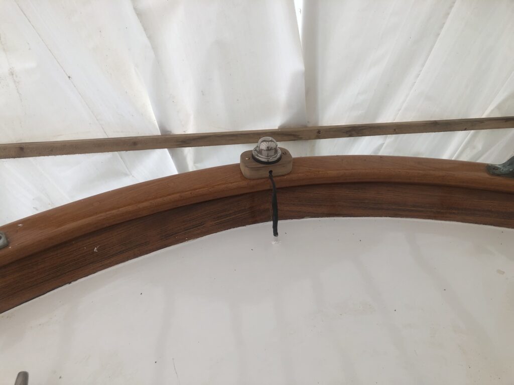
Here I’ve heat-shrunk the tubing and reinstalled the base. There is a bit of sealant where the wire goes through the deck.
One switch on the electrical panel turns on all three lights:
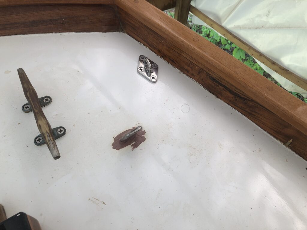
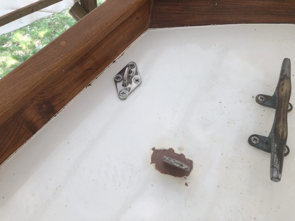
PAD EYES FOR MIZZEN RUNNERS
The mizzen mast is supported by a number of stays and shrouds, including two so-called “running backstays”, each of which can be loosened with a block and tackle to allow the mizzen boom to swing forward for off-the-wind sailing. On a port-tack broad reach, for example, the starboard-side runner would be slack, while the port-side runner is tensioned.
Before finishing the propane locker installation, I wanted to install the pad eyes to which the runners terminate. Here they are: