6/22/14: Bilge Bulkhead, Tanks, Compression Posts
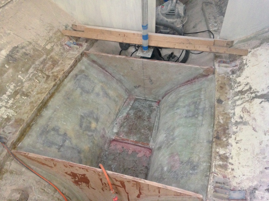
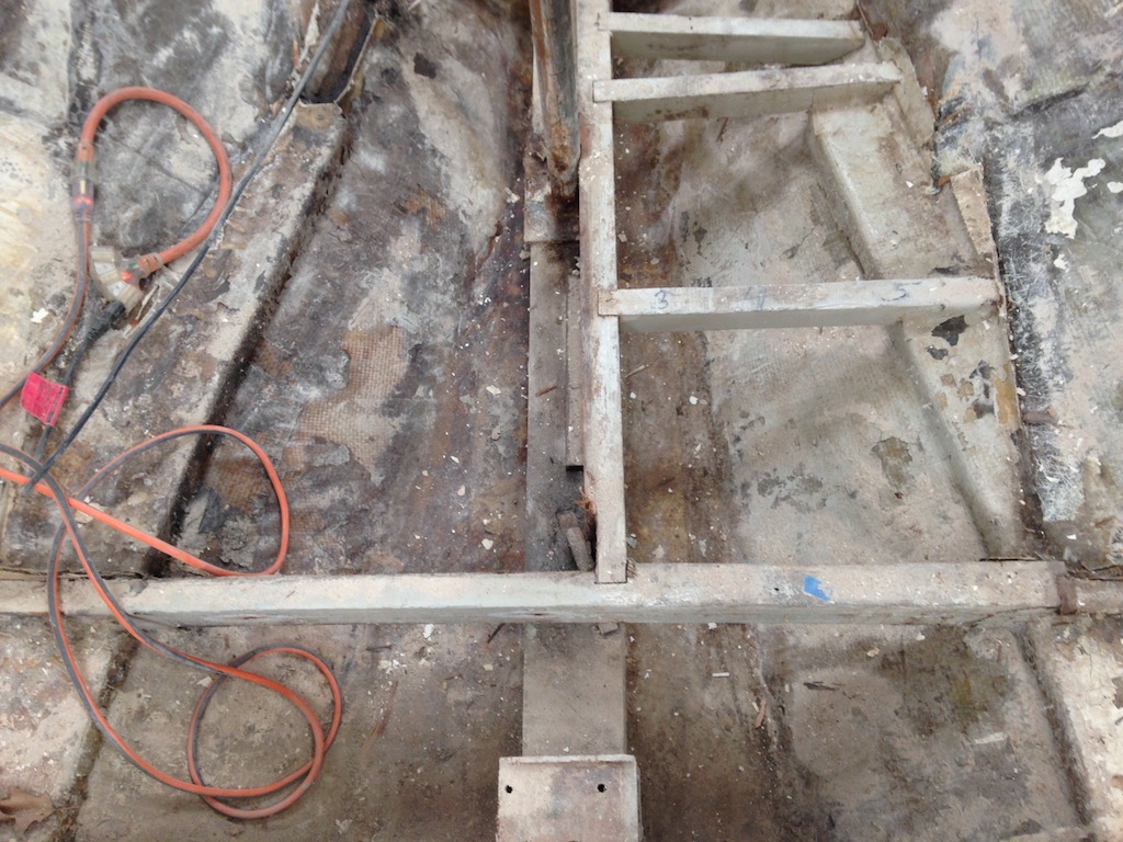
With the engine area rebuilt, and the engine back on its mounts, it was time to consider installing the bulkhead that separates the bilge area from the tanks area. The photo below shows a random-orbital sander on the bottom of the bilge. The new bulkhead will be installed just aft of the small bulkhead seen in the photo. (This small bulkhead will serve as a form while building the keel area up to its original height.)
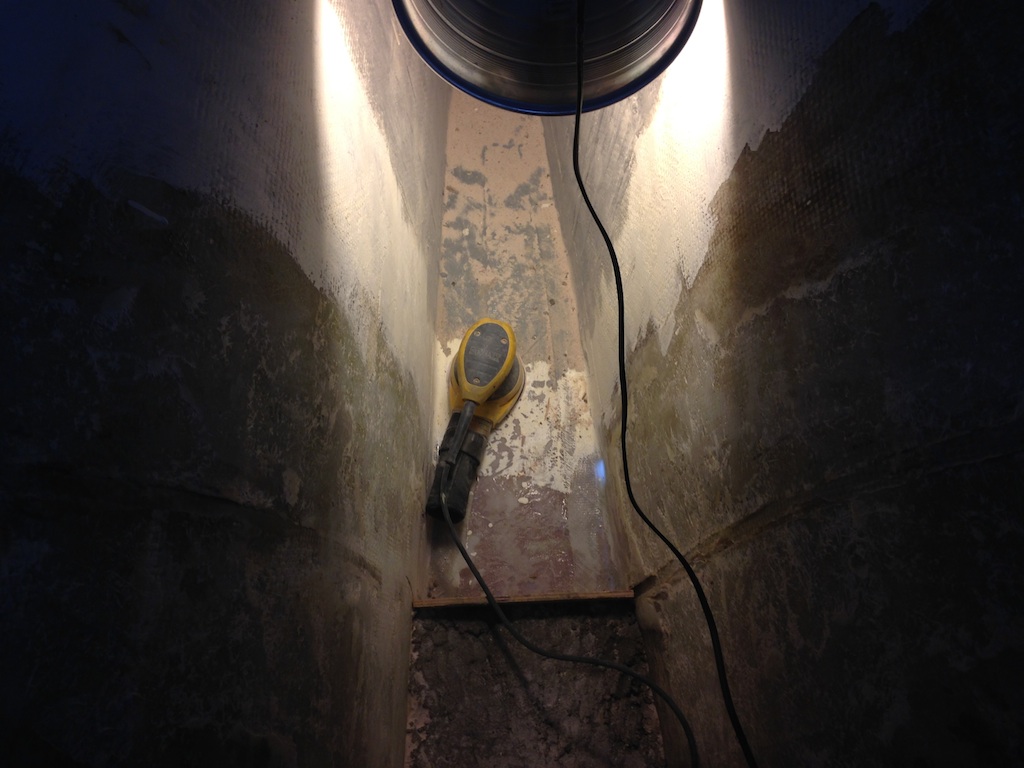
The bilge
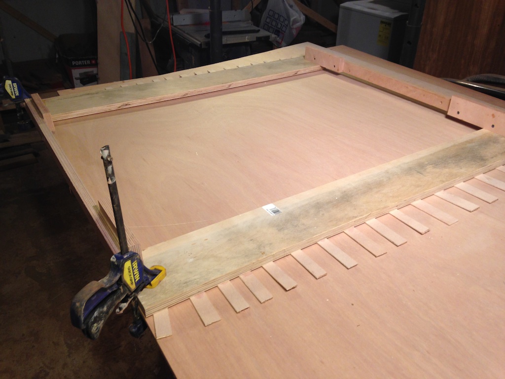
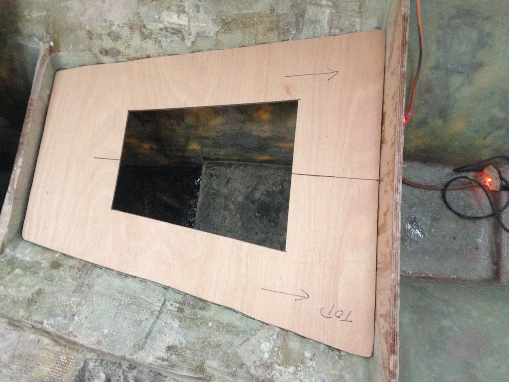
A pattern for the new bulkhead was constructed in the usual way, as shown below.
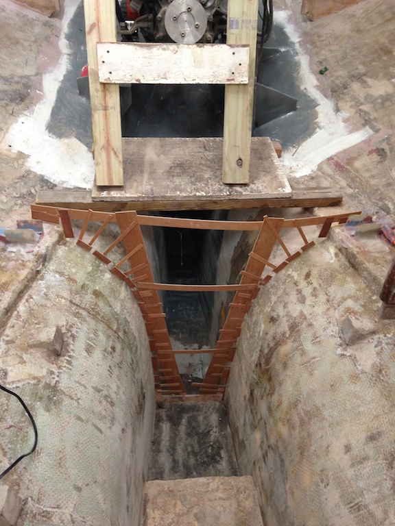
The pattern for the new bulkhead
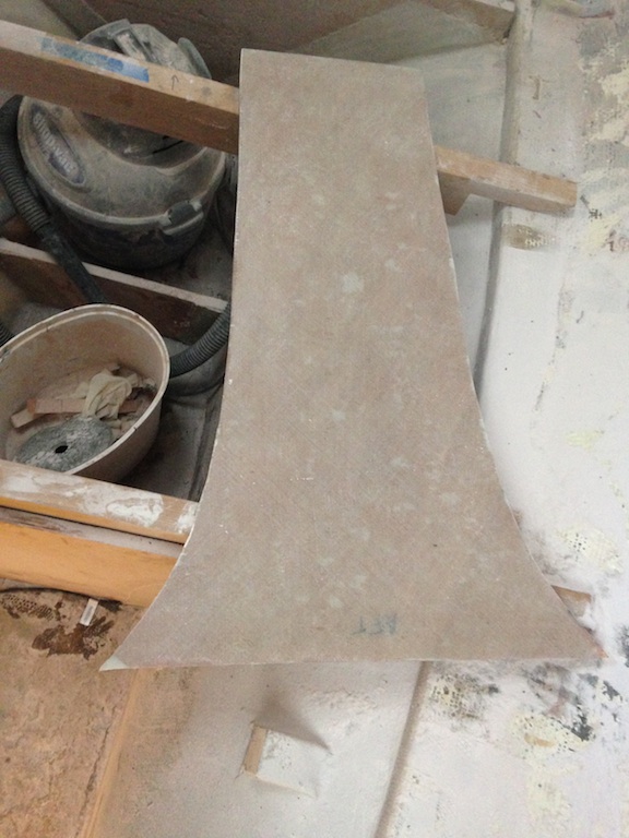
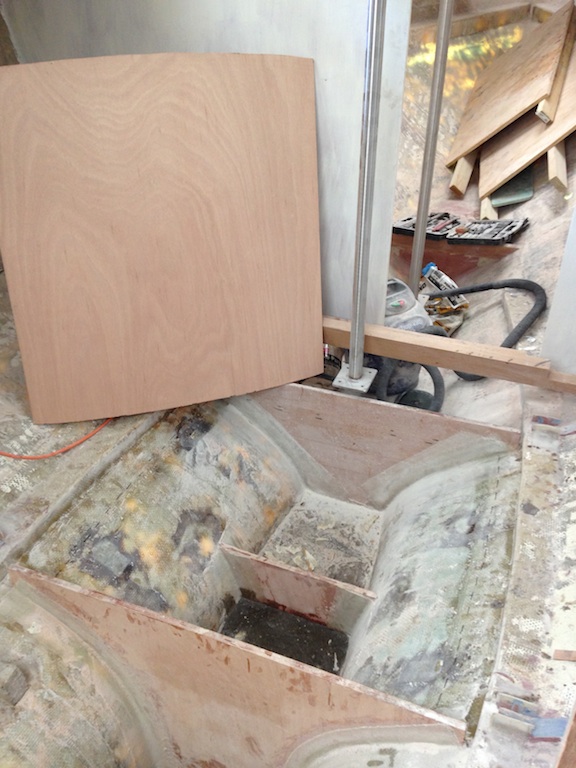
The new bulkhead was cut from 3/4″ Okume. The following photo shows the bulkhead and some of the layers of fiberglass that will cover both sides of the bulkhead.
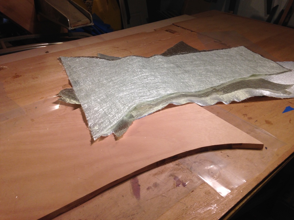
The new bulkhead, cut from 3/4″ Okume
Next, the fiberglass was applied to both sides of the bulkhead and left to dry. Each side received one layer of biaxial cloth and one layer of unidirectional cloth.
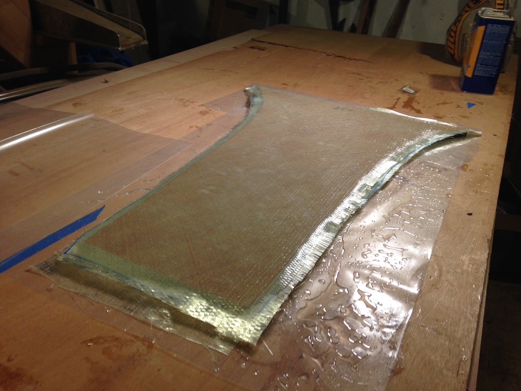
New bulkhead with fiberglass laminations
New bulkhead, ready for installation
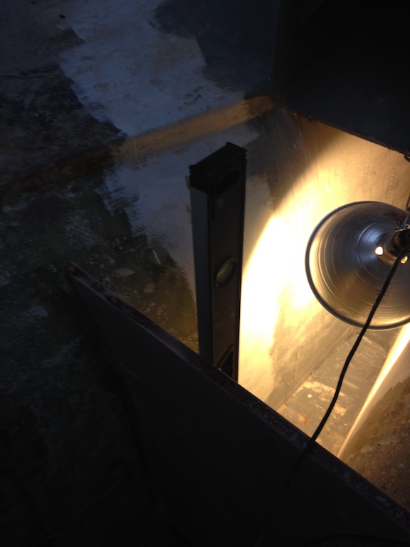
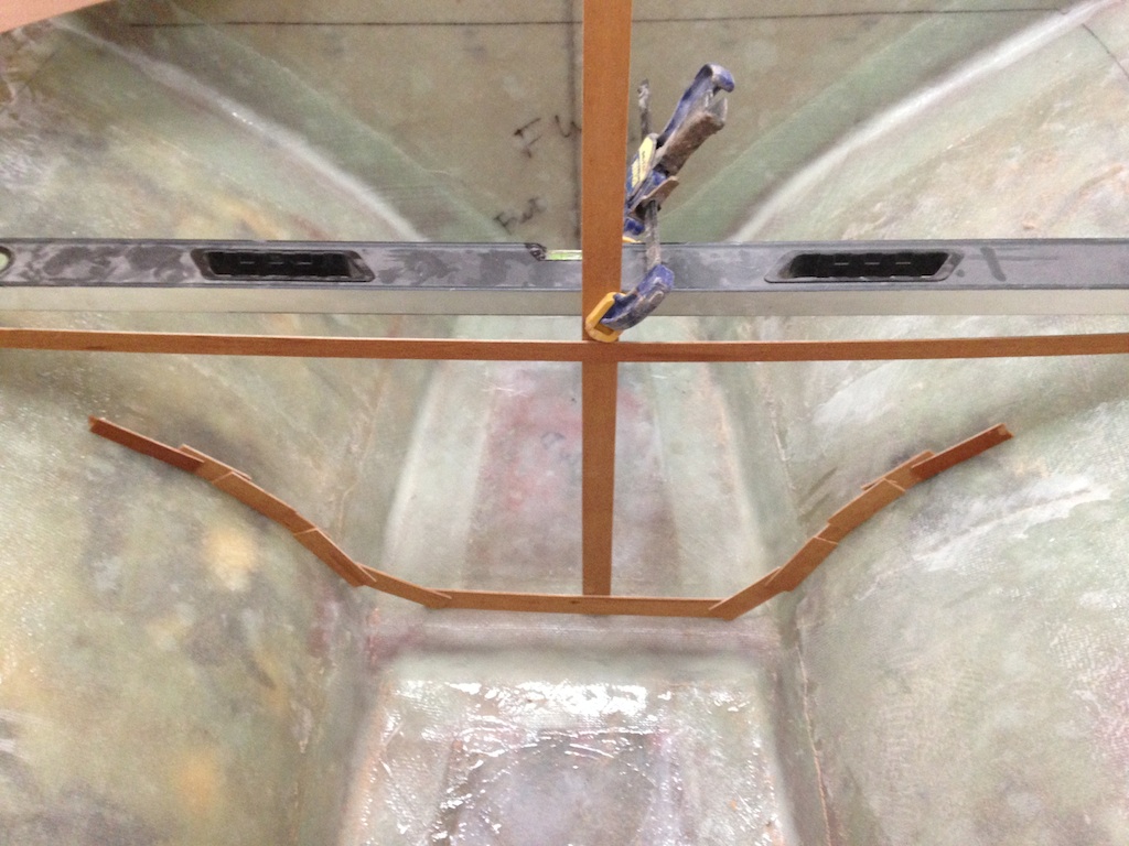
the new bulkhead, dry fitted, and being checked for verticality with a level
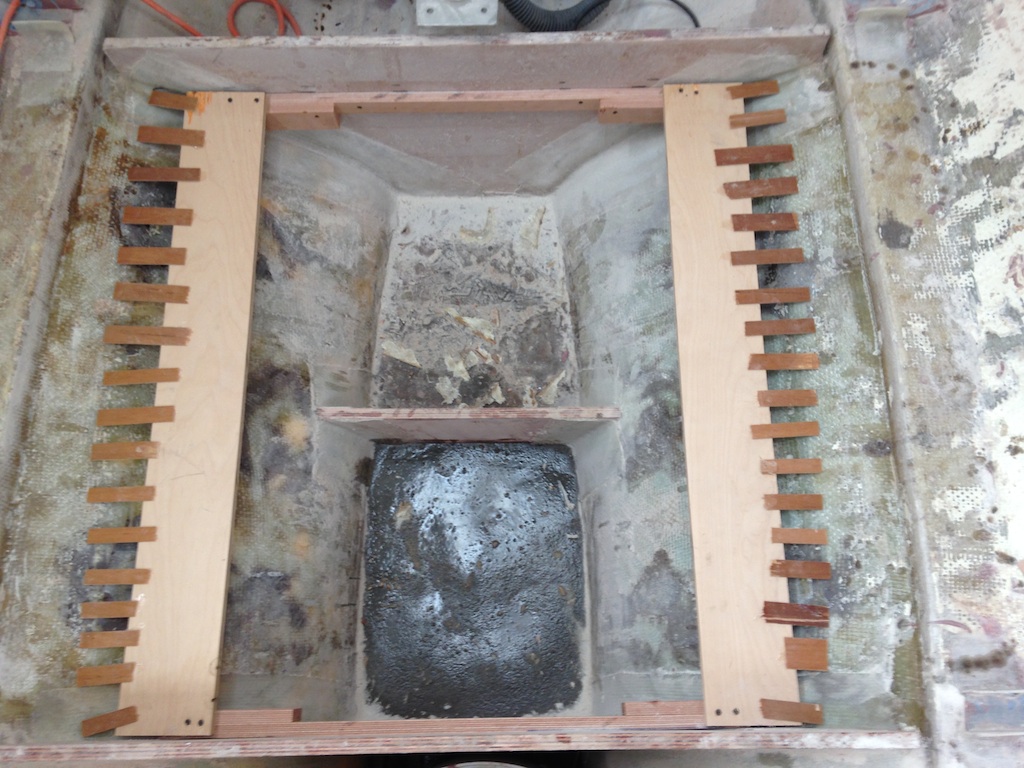
The top of the following photo shows the new bulkhead, which was bonded with fillets of thickened epoxy, then tabbed with three layers of biaxial cloth along each seam. The space between the two bulkheads seen here is where the aft water tank was located. Damaged concrete was removed from this area, so this area is being repaired by building up with a combination of wood, epoxy, and a sand/epoxy paste.
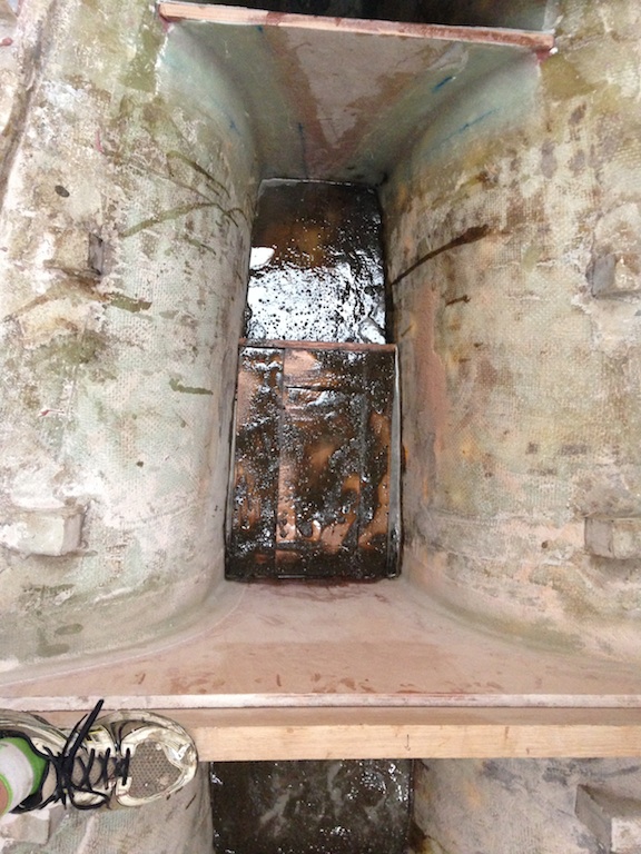
New bulkhead installed, and steps 5 and 6 being repaired
Meanwhile, serious consideration was given to the question of tanks. It was decided that integral tanks will be built. The following photo was taken during earlier stages of the project. Rough outlines of potential forward (red) and aft (green) tanks have been added. One tank will be the holding tank, while the other will be the freshwater tank. The capacities of each tank will be measured before deciding which one is which.
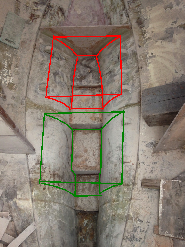
Rough outline for integral tanks
Each tank will have six sides, then internal baffles. Five sides are preexisting parts of the boat: the top of the keel, the starboard hull, the port hull, and two bulkheads. The photo below shows the pattern for the top (the sixth side) of the forward tank. The top will tilt slightly aft to allow drainage of any water that finds its way under the floors.
A pattern for the top of the holding tank
The top of the forwrd tank was cut from 3/8-inch Okume. This plywood will be built up on both sides by layers of fiberglass.
Tracing the pattern on 3/8-inch Okume
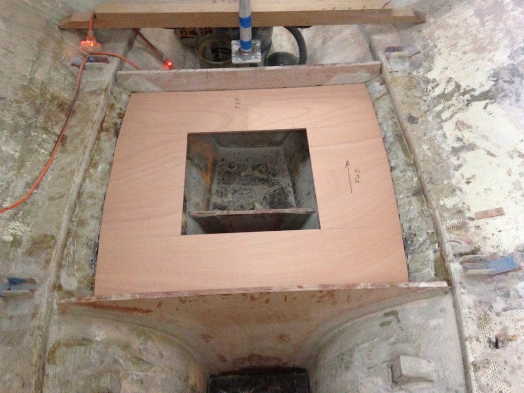
Next, the top was test-fitted.
The top of the forward tank, ready for a test fit
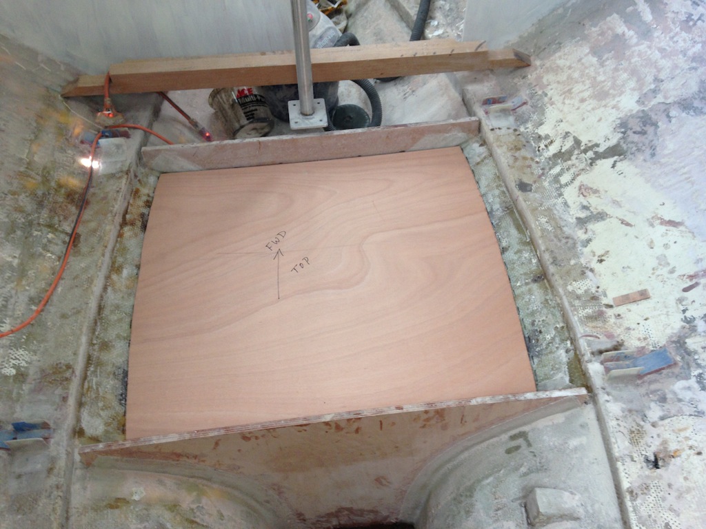
As usual, a good pattern and careful cutting ensures a good fit.
To facilitate both installation and maintenance, a large inspection port was cut out of the top. The jig saw was used, then the router was used to clean up the perimeter.
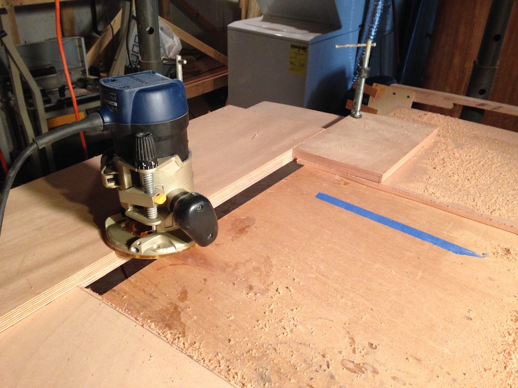
Routing a clean edge for the inspection port
A second test fit
Subsequent posts will cover the continued construction and installation of the top of the holding tank. Before installing the top, however, the other sides of the tank must be prepared. These sides will be covered with layers of biaxial cloth, with tabbing along the corners. The goal, of course, is a strong, completely impenetrable barrier between the contents of the tank and the rest of the boat.
The following photo shows the tops of the keel in the forward tank. These have been covered with thick layers of the epoxy/sand paste, then doused with straight epoxy. the concrete keel is now protected from water from above. This protection will increase further as the tanks are built.
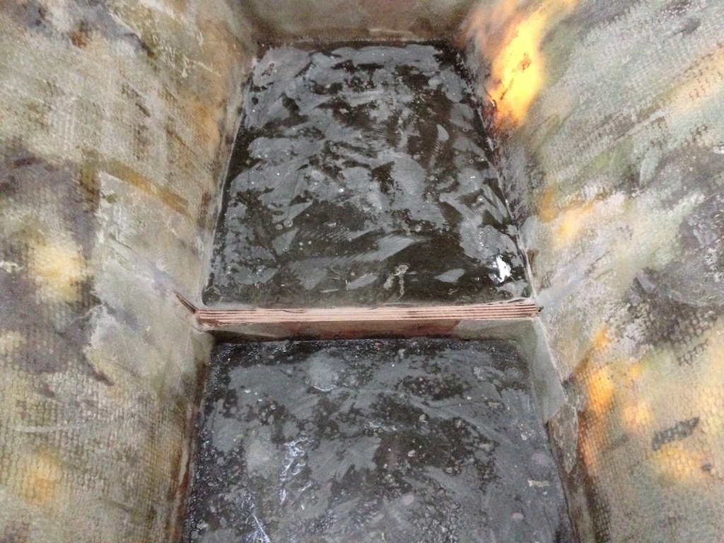
The tops of the keel
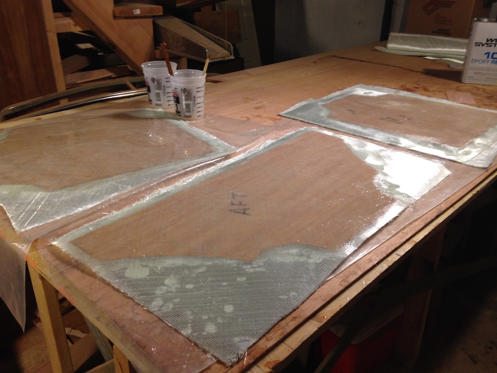
The sides of the tank will be covered with two layers of fiberglass cloth and two layers of tabbing along the seams: cloth, tabbing, cloth, tabbing.
Dry fitting fiberglass in the forward tank
The first layer of fiberglass was wetted out in place, rather than in advance. Large pieces are easy to fit into place while dry, but is difficult to work the resin into the cloth.
Forward tank with one layer of cloth
Plastic sheets cover the workbench while wetting out cloth in the workshop. The roll of plastic in the photo below is actually a very long tube of plastic, which was designed to be cut into sections and used to cover the slings of a Marine Travelift. This large roll might be enough for the entire restoration project.
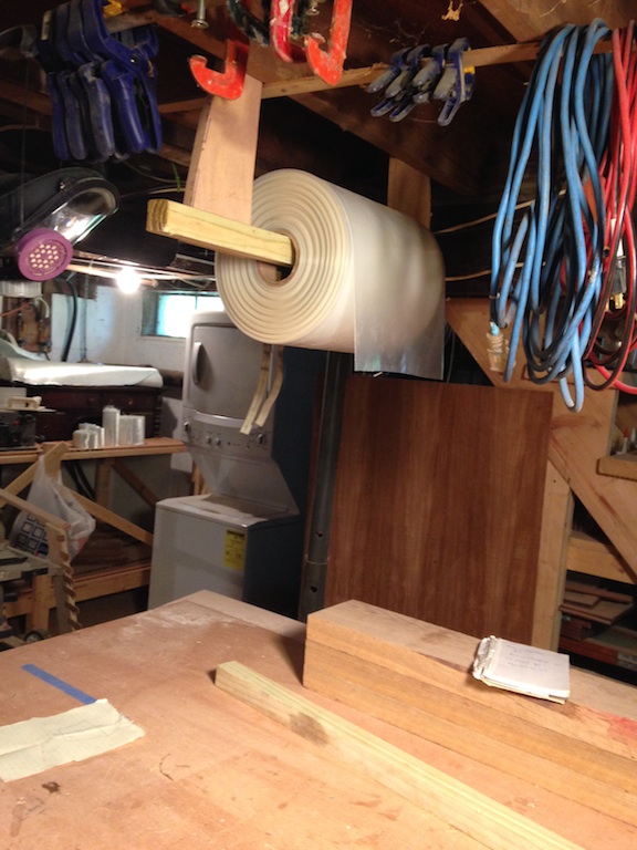
A roll of “sling strap” material
The next layer of fiberglass and the two layers of tabbing were wetted out in the workshop.
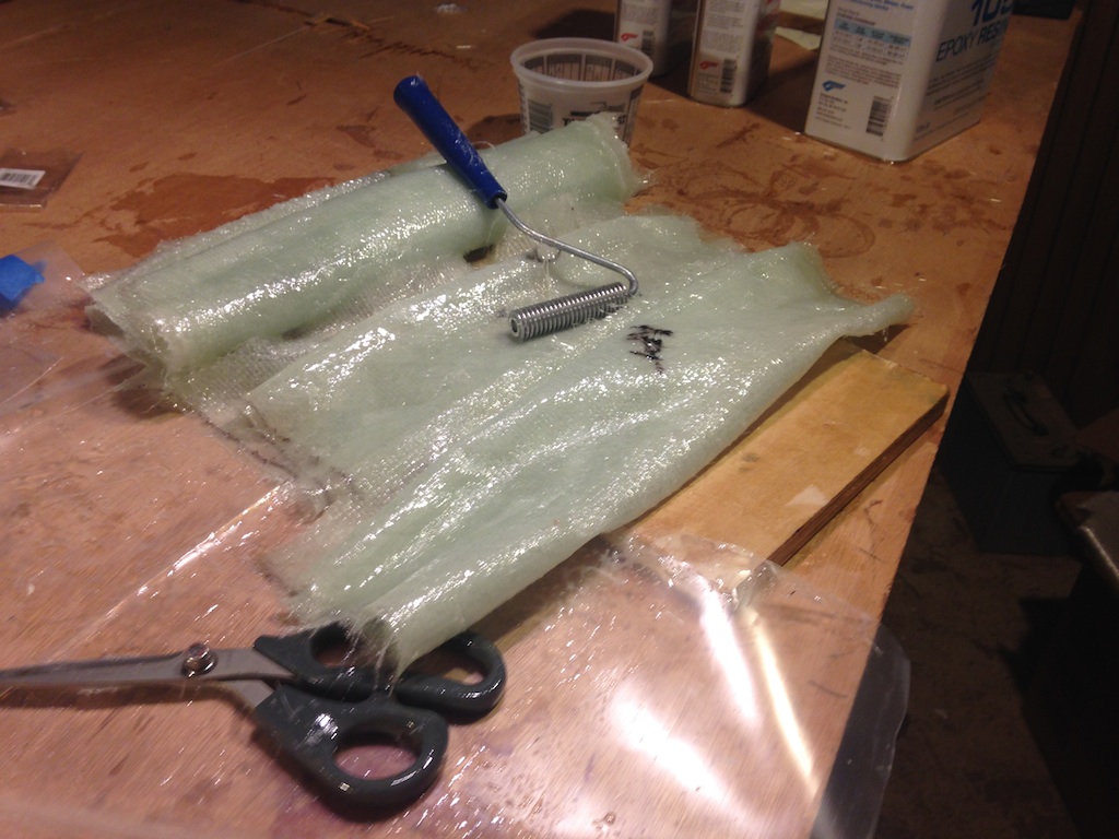
The grooved roller helps work resin into the glass and air bubbles out.
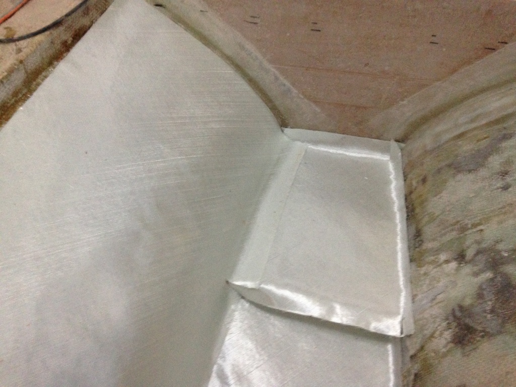
The following photo shows the inside of the forward tank after two layers of glass and two layers of tabbing have been applied. These bulkheads were installed with three layers of tabbing, so a total of five layers of tabbing bond these bulkheads to the hull.
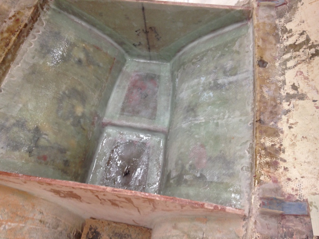
Two layers of glass and two layers of tabbing
Big tanks require internal baffles, which prevent the contents of tank from sloshing violently in a heavy seaway. These tanks are low and amidships, which is where there is the least motion. Partitioning this tank into four units will be sufficient. The following photo shows the pattern for the athwartship baffle under construction.
The pattern for a tank baffle
The baffles were cut from 3/8″ Okume. The baffles must include openings that allow the tank contents to move from compartment to compartment.
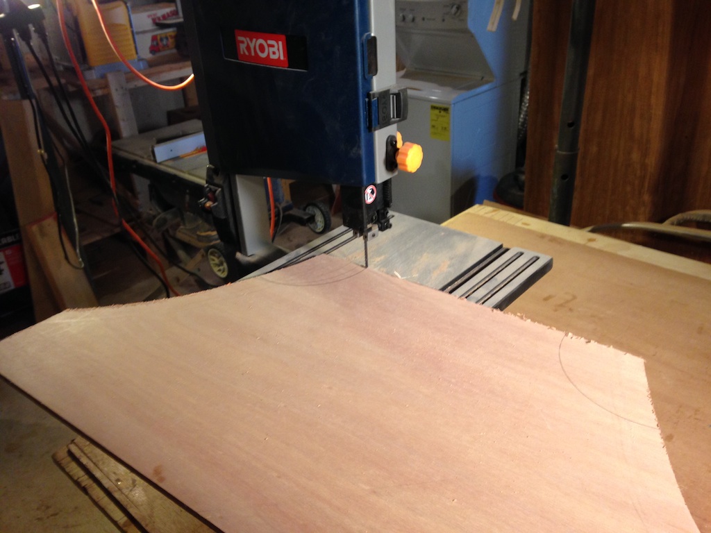
The band saw cuts an opening in the athwartship baffle.
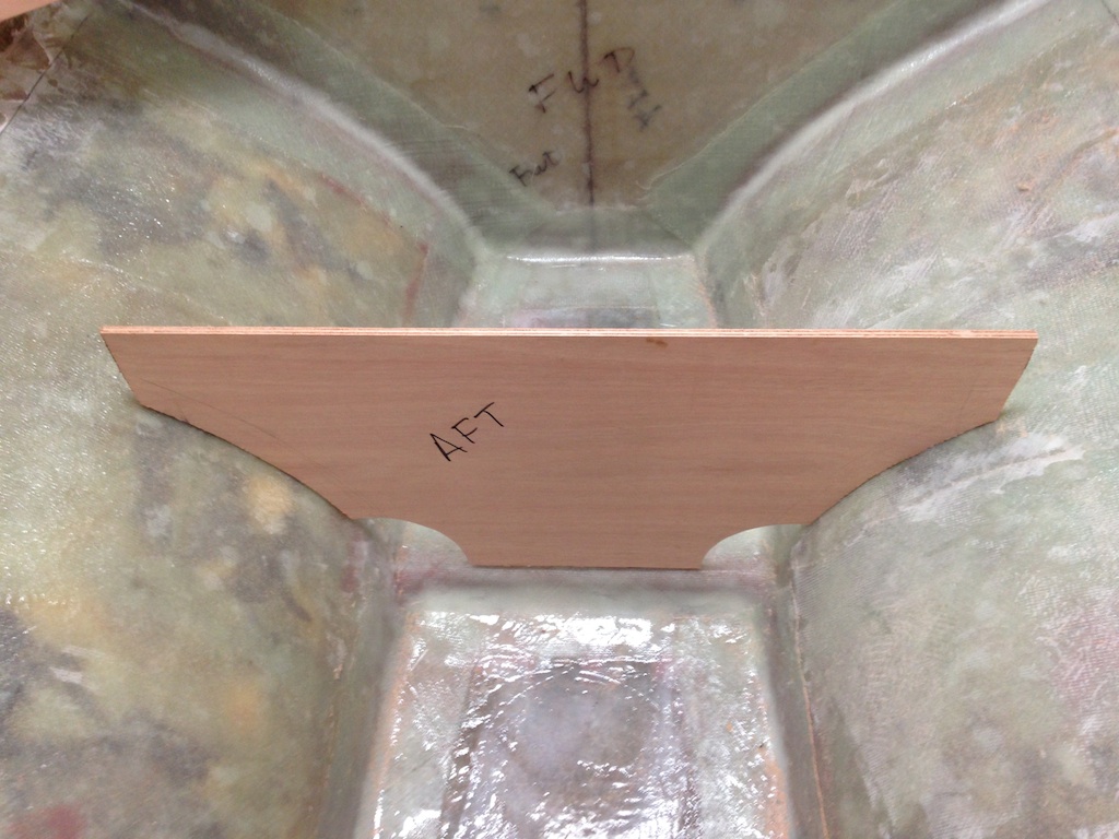
The athwartship baffle in place
The baffles that run fore-aft have a fairly simple shape, so the patterns are correspondingly simple.
The pattern for the forward side of the fore-aft baffle
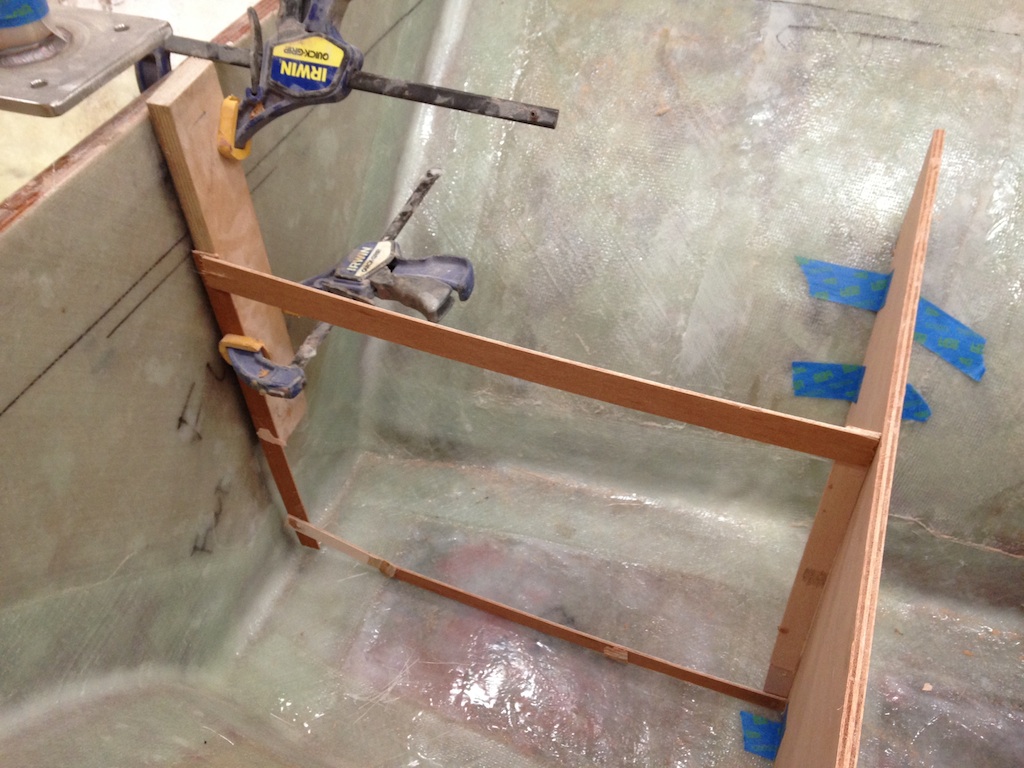
The following photo shows the baffles dry-fitted in the tank.
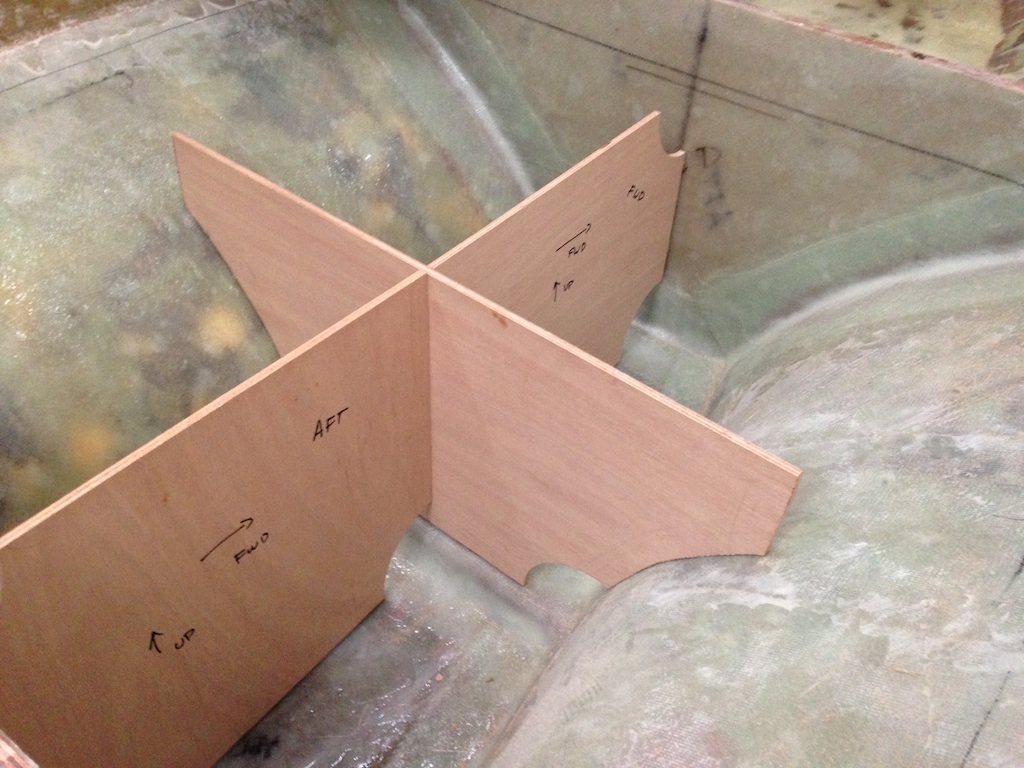
A four-compartment tank
As we have seen, the inspection port is very generous, and here we can see that there will be easy access to all points in the interior of the tank.
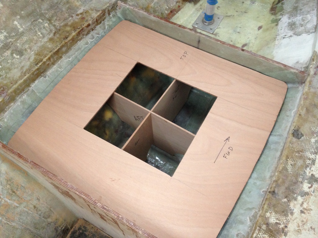
The top of the tank and baffles
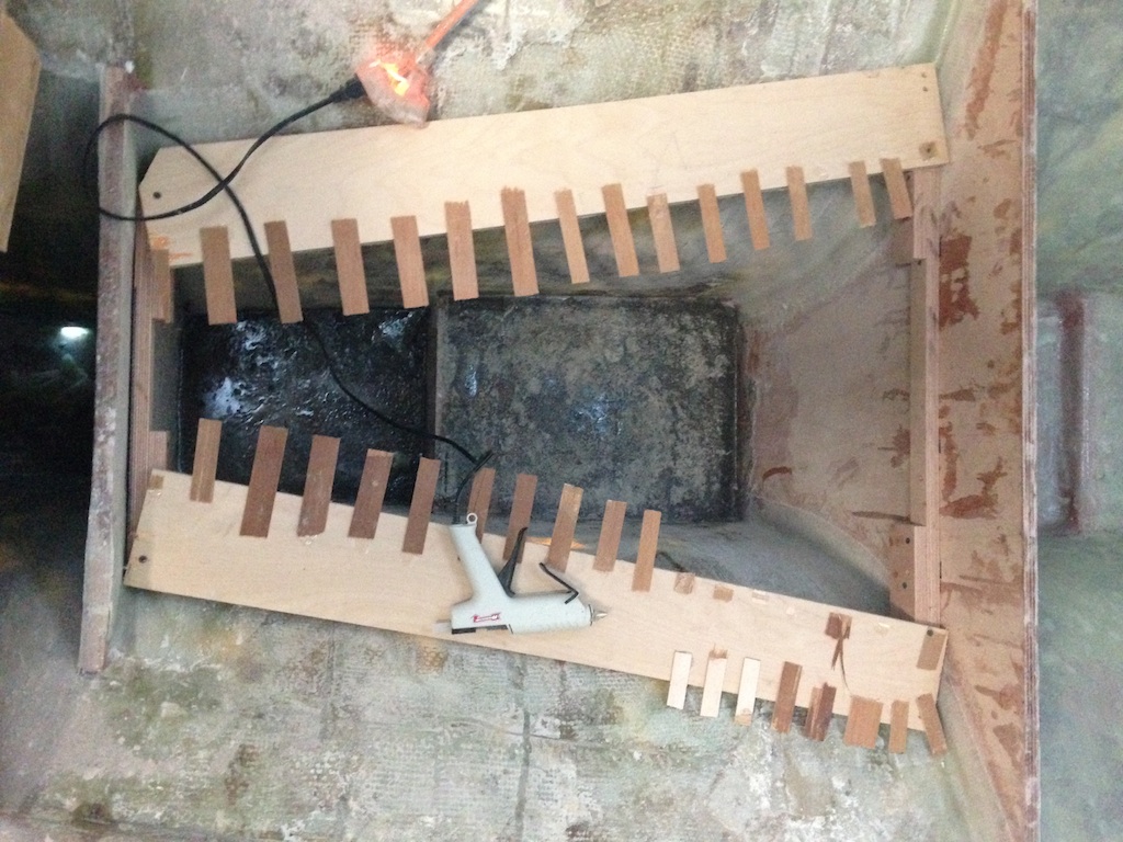
To strengthen the baffles (and as a first measure to seal them), they were covered on each side with biaxial fiberglass cloth.
Strengthening and sealing the baffles
Meanwhile, the pattern used to make to top of the forward tank was modified and then used to make the pattern for the top of the aft tank.
The pattern for the aft tank under construction
The aft tank has a different shape from the forward tank, which is evident from the shape of the top.
The top of the aft tank
Meanwhile, the (new) compression posts that support the mast step were bolted to the coachroof, as shown in the following photos.
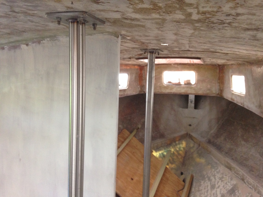
Two of the three new compression posts
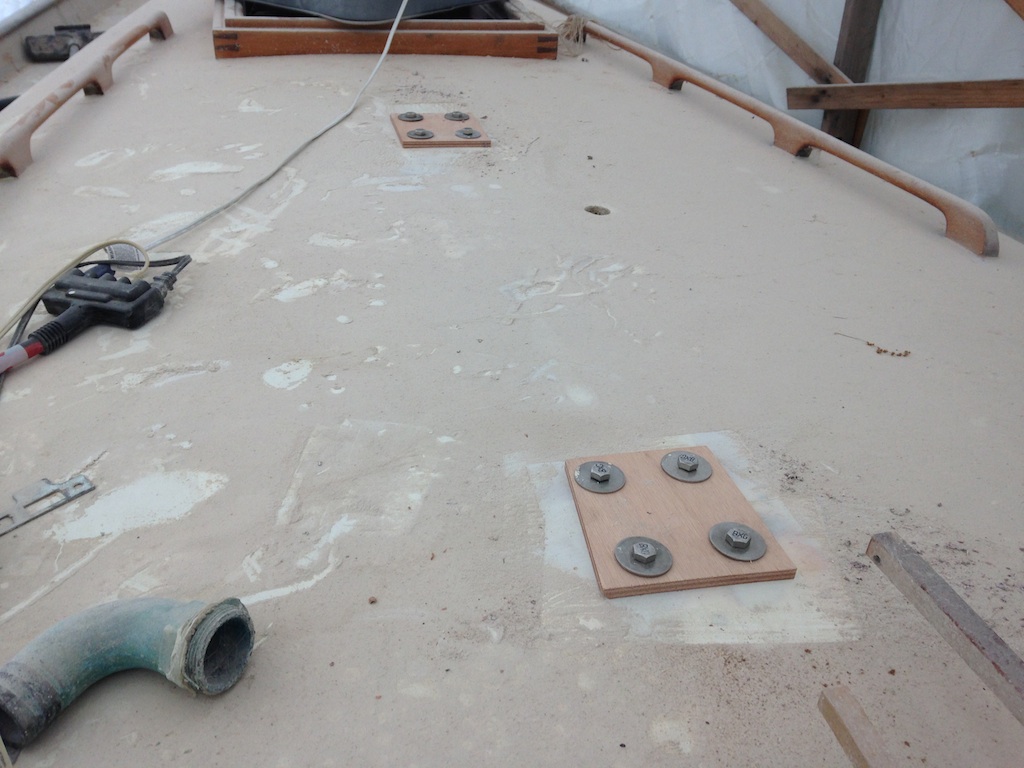
The temporary bolts here are where the mast step sits
The following two photos were taken in a previous stage of the project. The first shows the forward compression post. The bottom of the post is screwed to the top of a long, wide, and tall block of wood. The second shows the block of wood after removal.
The old forward compression post and its wooden support

The bottom of the big block is wet.
The original block of wood will not be used, and the following photo shows the space under the bottoms of the compression posts that must be filled. There is 11.5″ of clearance below the aft compression post and 7″ of clearance below the forward compression post.
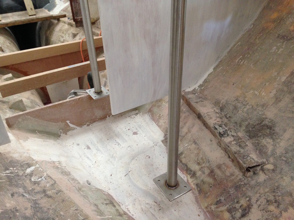
The bottoms of the posts are not yet supported
The new block of wood will be made up of a lamination of white oak. The following photo shows the bottom piece of oak and we can see that there is an unacceptable gap between the “floor” and the wood.
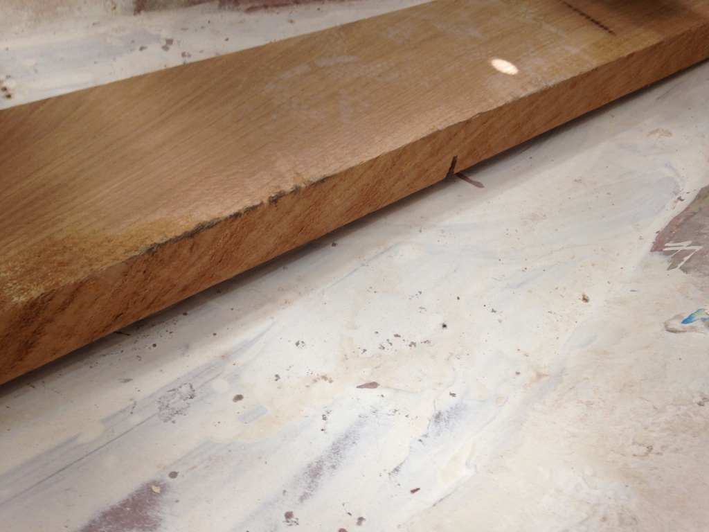
The bottom piece of white oak
The gap may be reduced either by building up the floor or shaping the wood. The floor is smooth, but not flat, and shaping the wood was the easier option. The wood was shaped using a combination of sanding and planing. The result was a much smaller gap, which will disappear by coating the bottom of the block with thickened epoxy before installation.
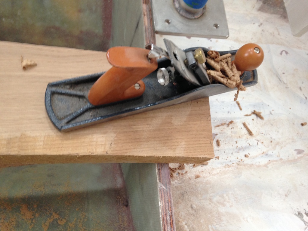
Planing the forward end of the wood
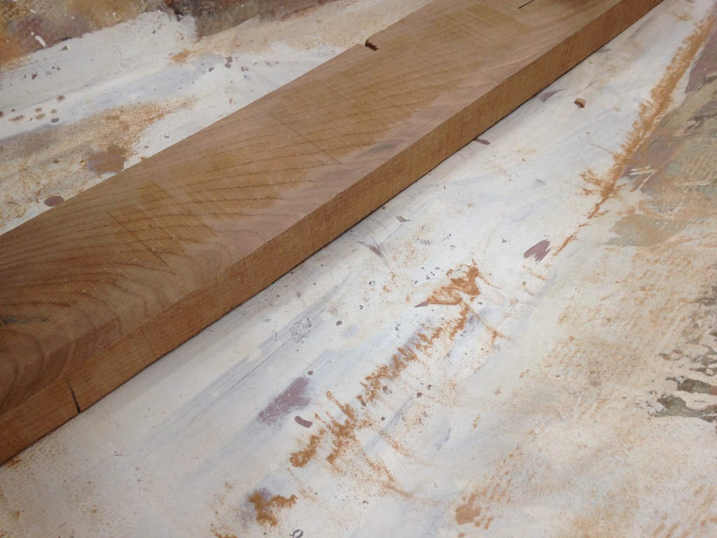
A much smaller gap
The white oak was 8/4 and about 6″ wide and 4′ long. (In woodworking terminology, X/4 wood is X/4″ thick before milling. Thus, 8/4 wood is 2″ thick, 6/4 is 1.5″ thick, and so on.) The following photo shows three pieces of oak that have been laminated together using thickened epoxy.
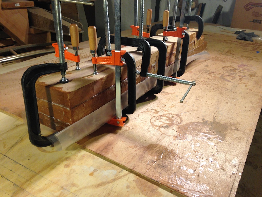
Clamping
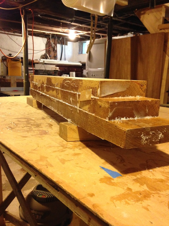
Clamps removed
The following photo shows the new and old blocks of wood side by side. The new block is wider, and is made of denser, harder wood.
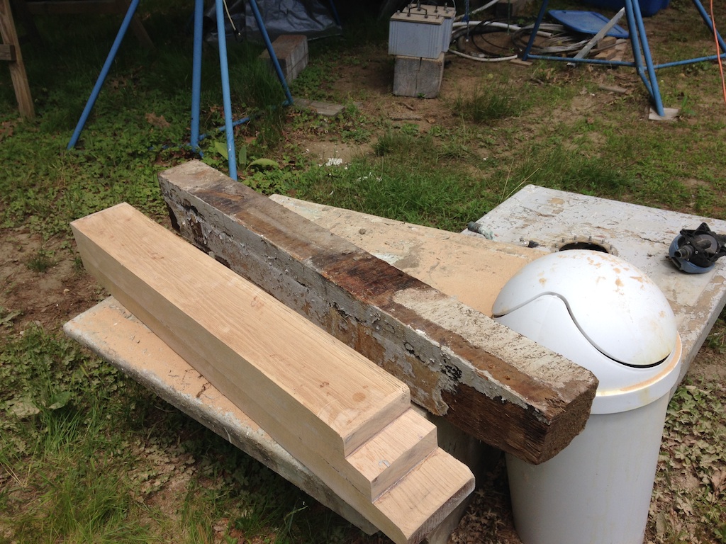
The new (left) and the old (right)
The next step will be to install the new block of wood, then build it up to the bottoms of the new compression posts.
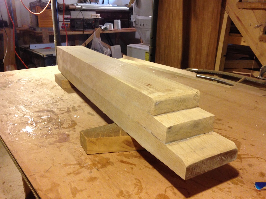
Ready for installation