4/16/23: Engine, Water Heater, New Tank Gaskets, Pedestal
ENGINE
You may recall the image below from THIS POST. This is the wire cluster that connects the engine panel in the cockpit to the engine.
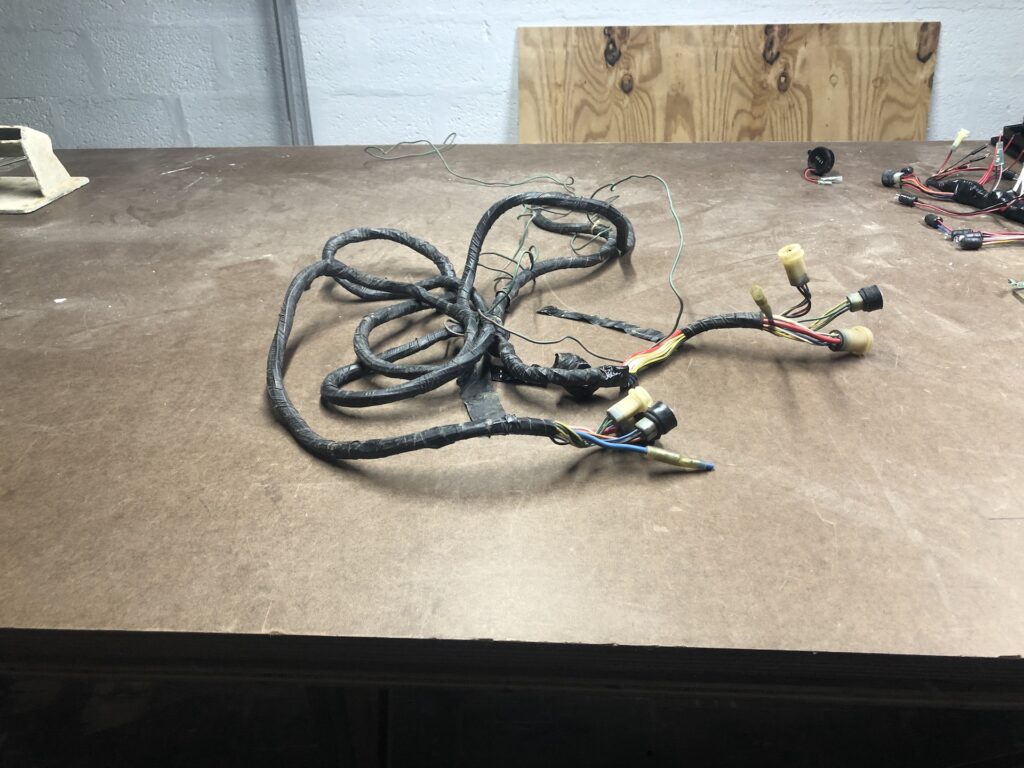
My mechanic/systems guy was over and we connected three battery cables to the engine (a positive to the starter, and two negatives to the engine block). We also connected the wire cluster to the panel and engine. The wire cluster is much longer than necessary, as you see below where it is lying all over the top of the engine.
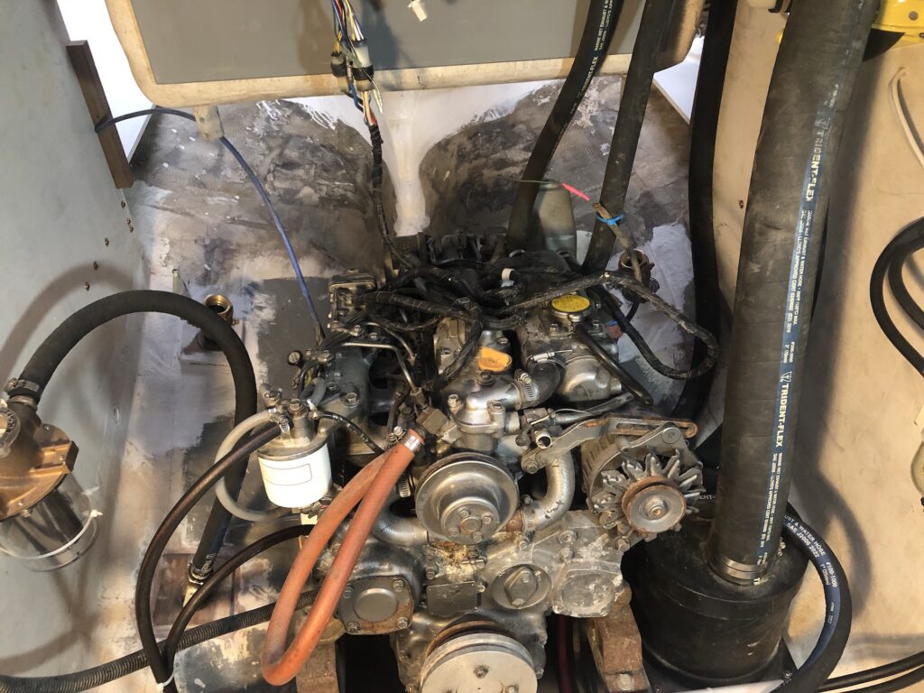
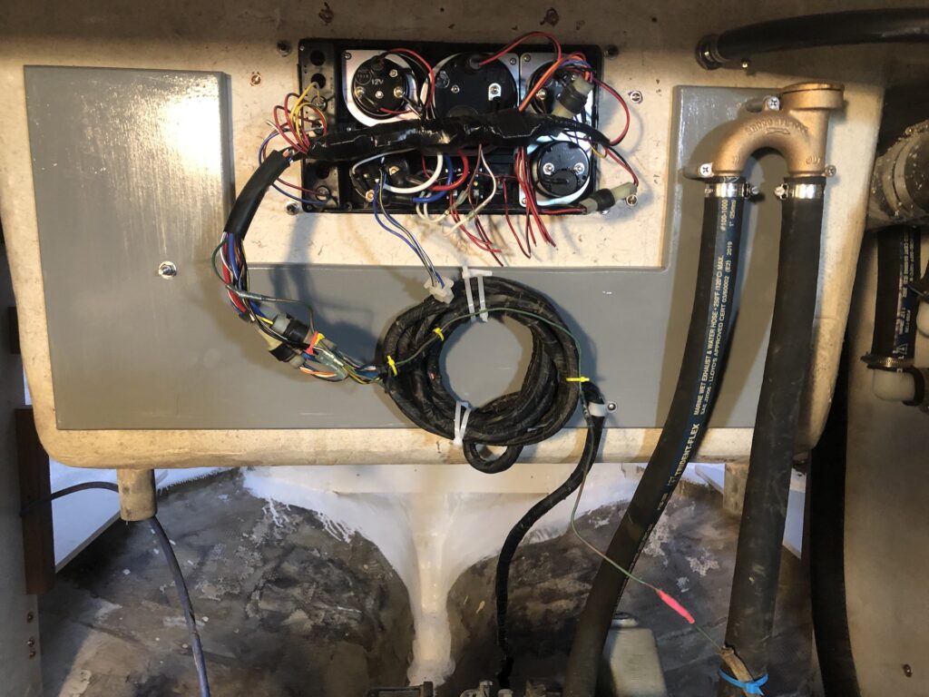
Here I’ve coiled the extra up and zip-tied it to the over-engine board that was designed for such purposes:
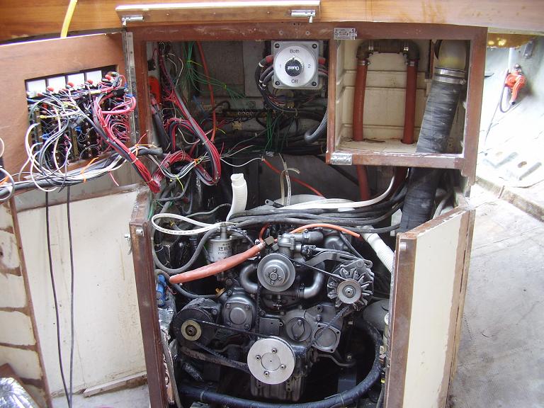
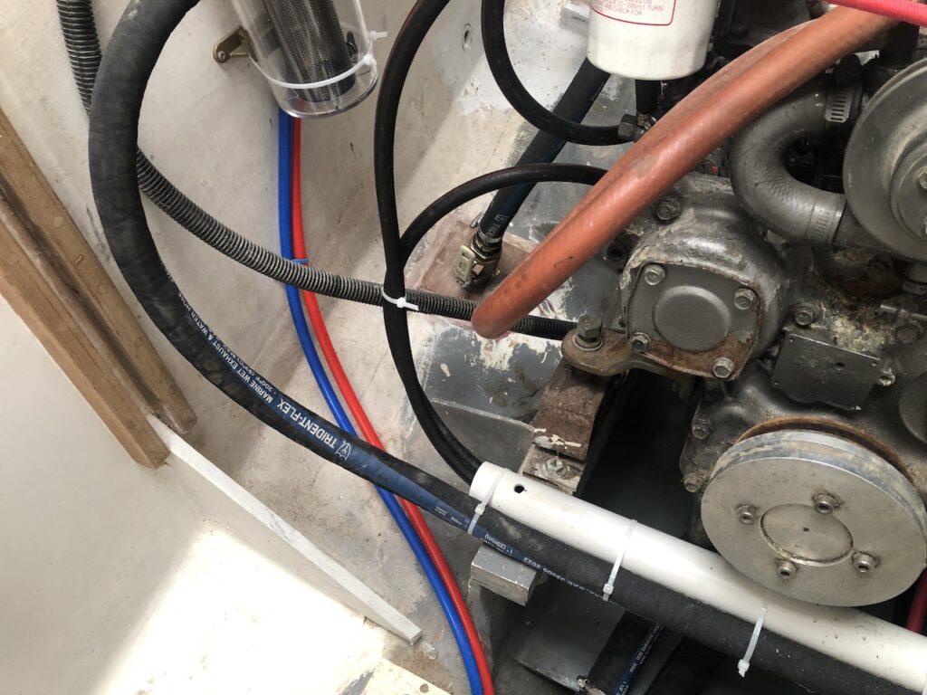
As of this writing, the fuel system is completed, the raw water plumbing is completed, and the engine’s electrical system is completed. Besides two coolant hoses that run to and from the water heater, and the hot- and cold-water plumbing, the image below shows what the engine compartment will look like from the front end.
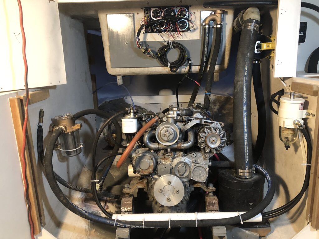
Recall that my rebuild includes a generous increase in access space all around the engine. As a means of comparison, the image below shows the engine compartment in its previous state.
WATER HEATER
The water heater can heat water in two ways: (1) Via a 120-V AC electrical connection that powers heating elements within the heater, and (2) via an internal heat exchanger through which hot engine coolant runs.
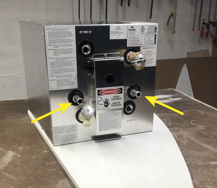
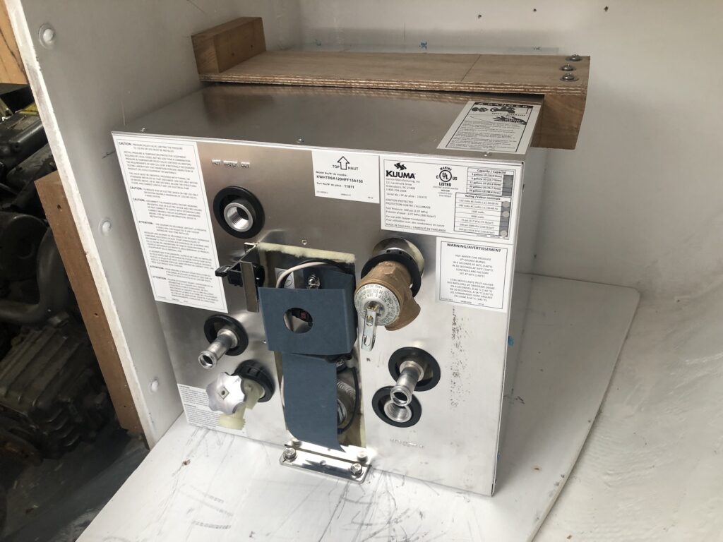
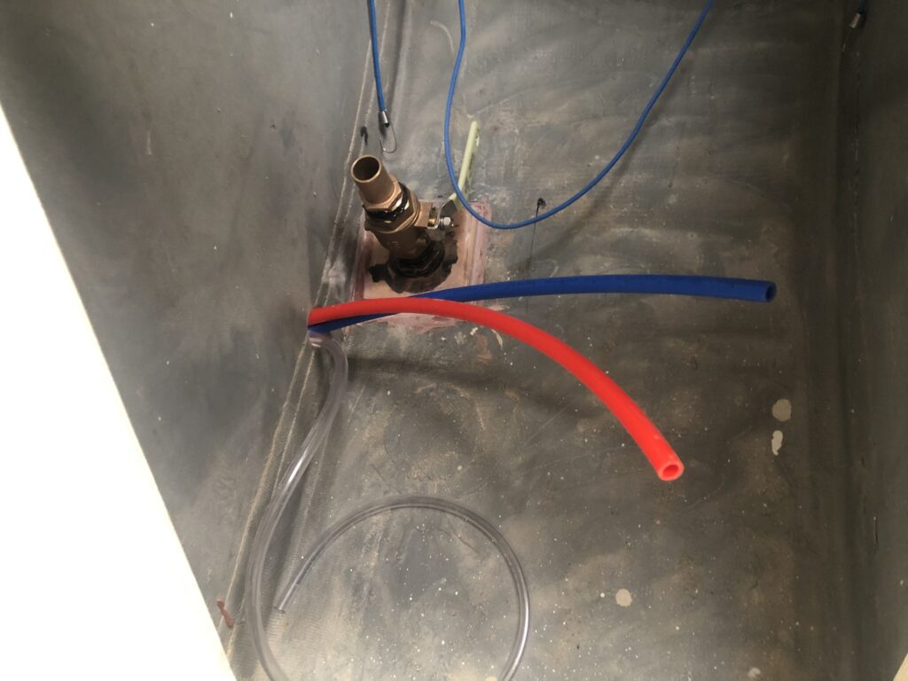
The water heater must be installed “at or below engine level” according to the manual. Through a little investigation, consultation, and brainstorming, I would like to revise this directive to read: The highest point in the plumbing that takes coolant from the engine to the water heater and back must be at or below the level of the coolant fill-cap on the engine. The reason is that there should not be air bubbles trapped in the coolant flow, and the plumbing cannot be filled completely with coolant unless the fill point is the highest point. The image below shows the coolant’s entry and exit points on the water heater (yellow arrows).
I was able to determine that, when the heater is in its installed position, these points are just below the level of the coolant cap. I do not, however, know the geometry of the heat-exchanger piping inside the water heater. If the inside piping rises above the level of the entry and exit ports, then the water heater might be too high.
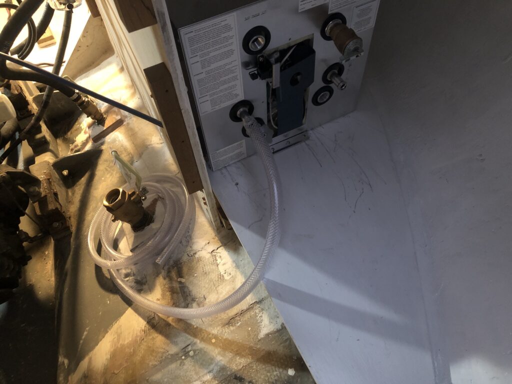
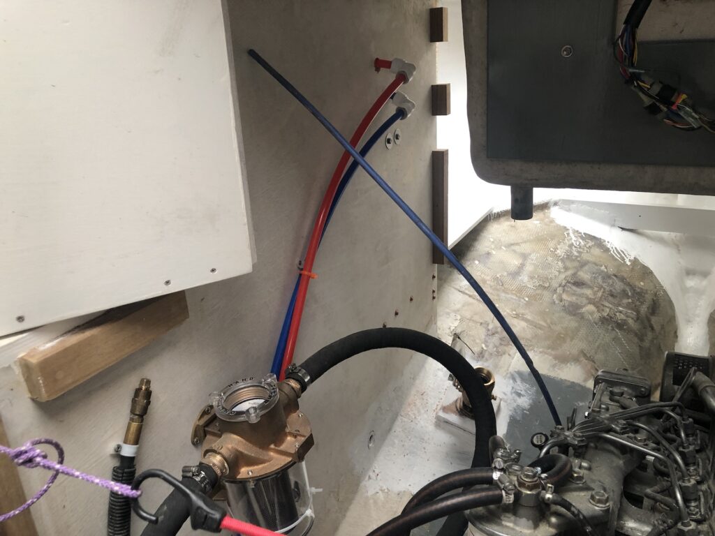
I devised a simple experiment to solve this mystery. In the image below you can see a piece of clear hose connected temporarily to one of the coolant ports on the water heater.
I took the other end of the hose to the coolant cap and raised it above the coolant cap. Next I poured water into the open end until I was sure a steady, air-bubble-free flow was established in the hose and through the heat exchanger.
While I was still pouring water into the hose, I simultaneously stopped pouring the water and plugged the end of the hose with my thumb for a fraction of a second (to stop the momentum of the water). Then I let everything settle after removing my thumb.
What I found, pictured below, is that the water level in the hose settled just below the level of the coolant cap.

The image below illustrates, schematically, my findings. Simply speaking, since “water seeks its own level”, the water at the free end of the hose is at the level of the highest plumbing in the heat exchanger (minus the diameter of the piping).
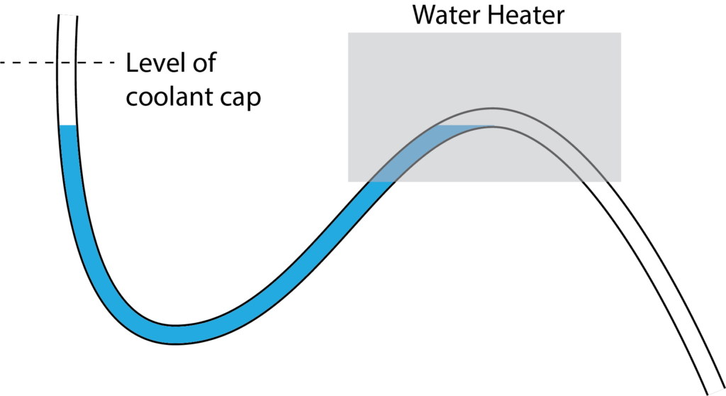
This is good news. In fact, I put a level on a salon floorboard and found that the boat has settled a bit “bow down” so when the boat floats level, then the water tank will be even a bit lower relative to the coolant cap.
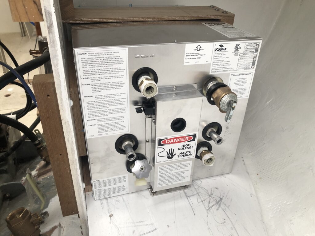
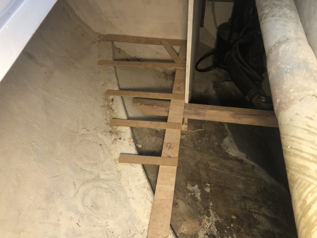
Below I’ve bolted the water heater to its floorboard via the aft flange (the forward flange is secured under a teak cleat, as discussed in the previous post). The heater should be immobilized by the flange connections, but as an extra precaution, I blocked it in against the bulkhead (for support while heeled to port) and I built and installed the wooden Z-shaped contraption you see below (for support while heeled to starboard.)
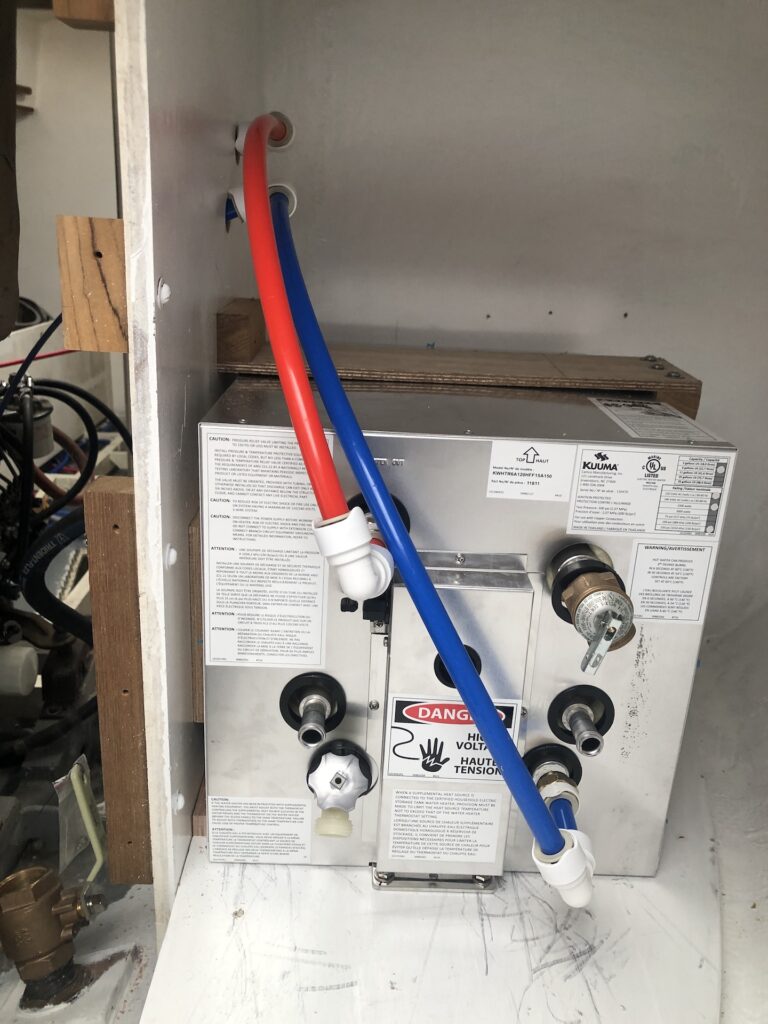
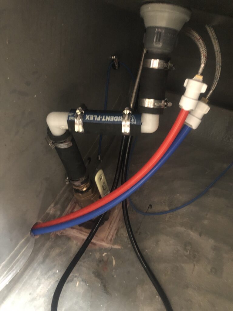
Below I’ve installed quick-connect fittings for water in and water out, as well as the cover for the wiring area. At this time I’m not going to wire the heater. Heating by electricity requires being at a dock and plugged into shore power. Wiring the unit will be easy if I ever feel the need, but for now running the motor for 5 minutes should produce plenty of hot water for a few showers or to wash some dishes.
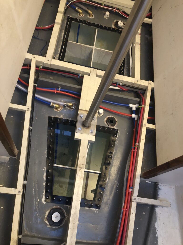
Meanwhile, the under-floorboard area continues to get busier with wiring and plumbing.
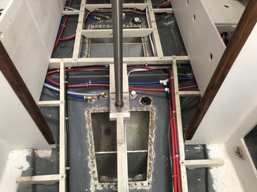
The three hoses below lead up into a starboard locker…
…and back into the area under the galley sink. The clear hose is for the ice-chest drain and leads to the bilge.
Here are the lines for cold water to, and hot water from, the water heater.
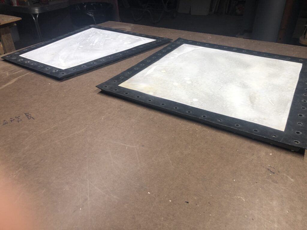
WATER-TANK GASKETS
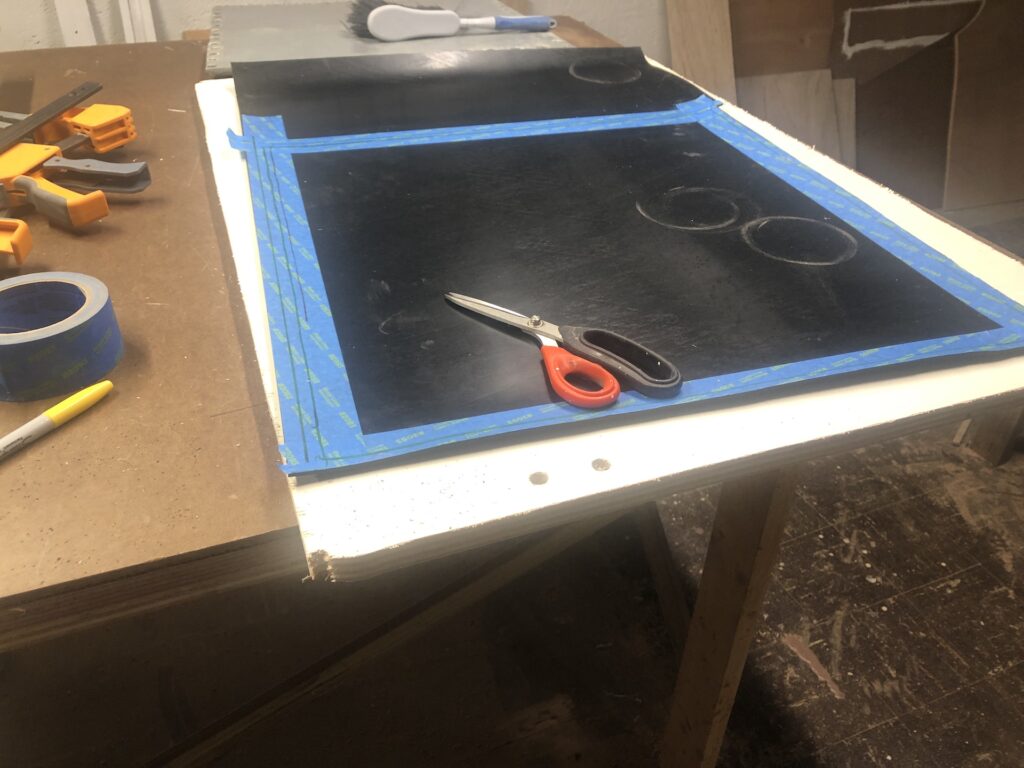
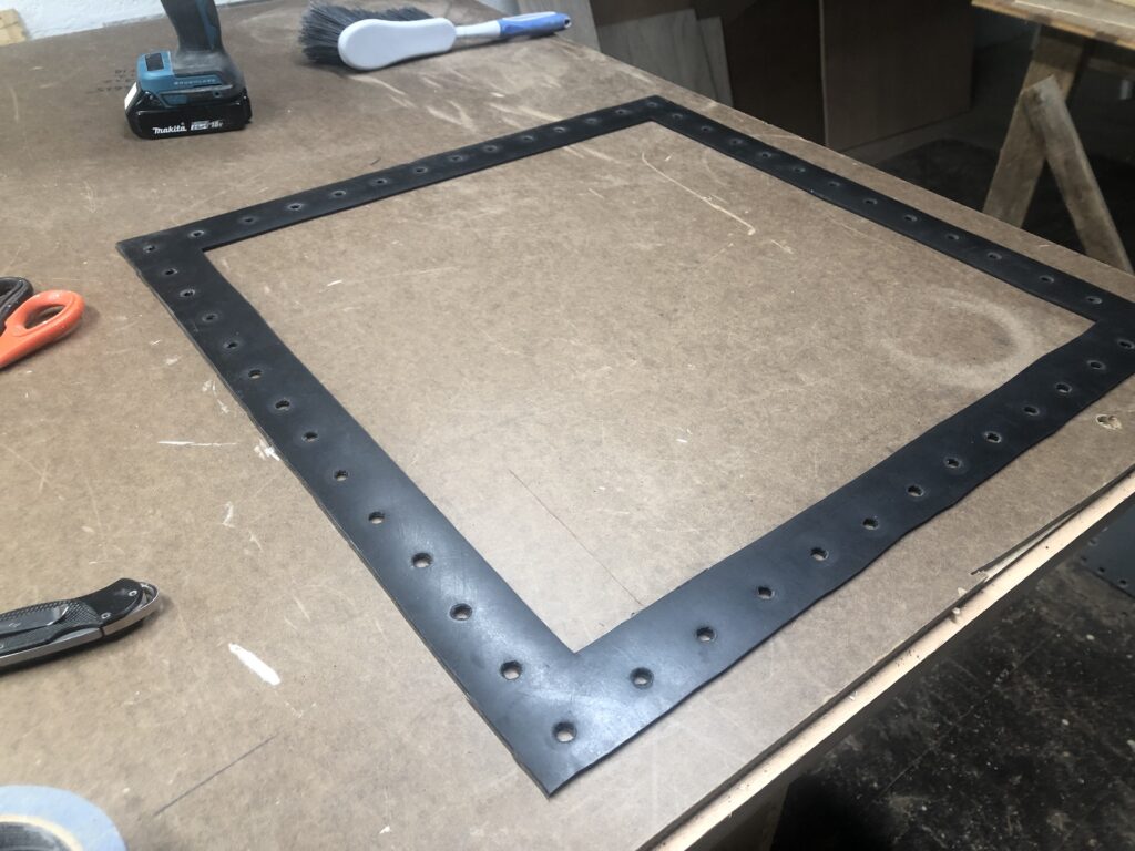
Back in 2014 I made gaskets for the water-tank lids. Upon opening the tanks recently, I found those old gaskets to be crusty and a bit brittle, so new gaskets are required. I ordered a few 2ft by 3ft sheets of 1/8″ thick EPDM rubber (same as last time) and got to work:
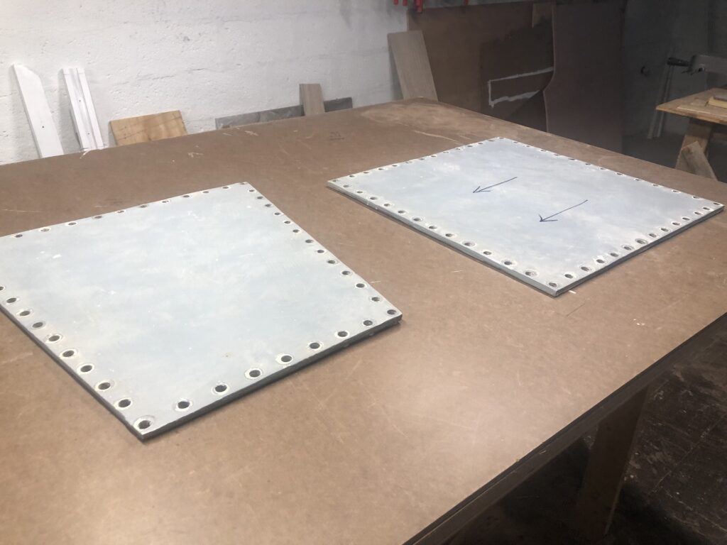
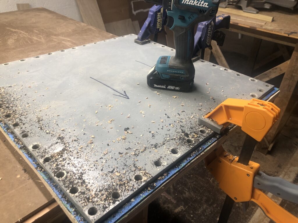
Once again, I simply used the lids as drill templates.
Back up on the boat, I lubed the gaskets and installed the lids:
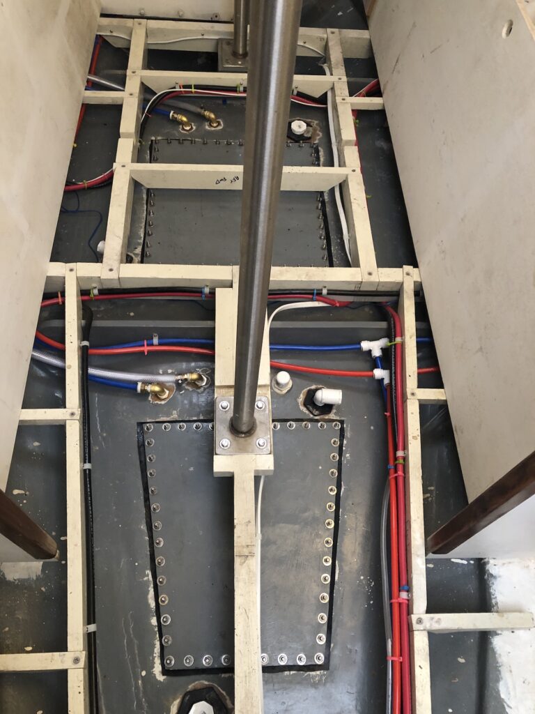
Next, I plumbed the sinks. Here is the view under the head sink:
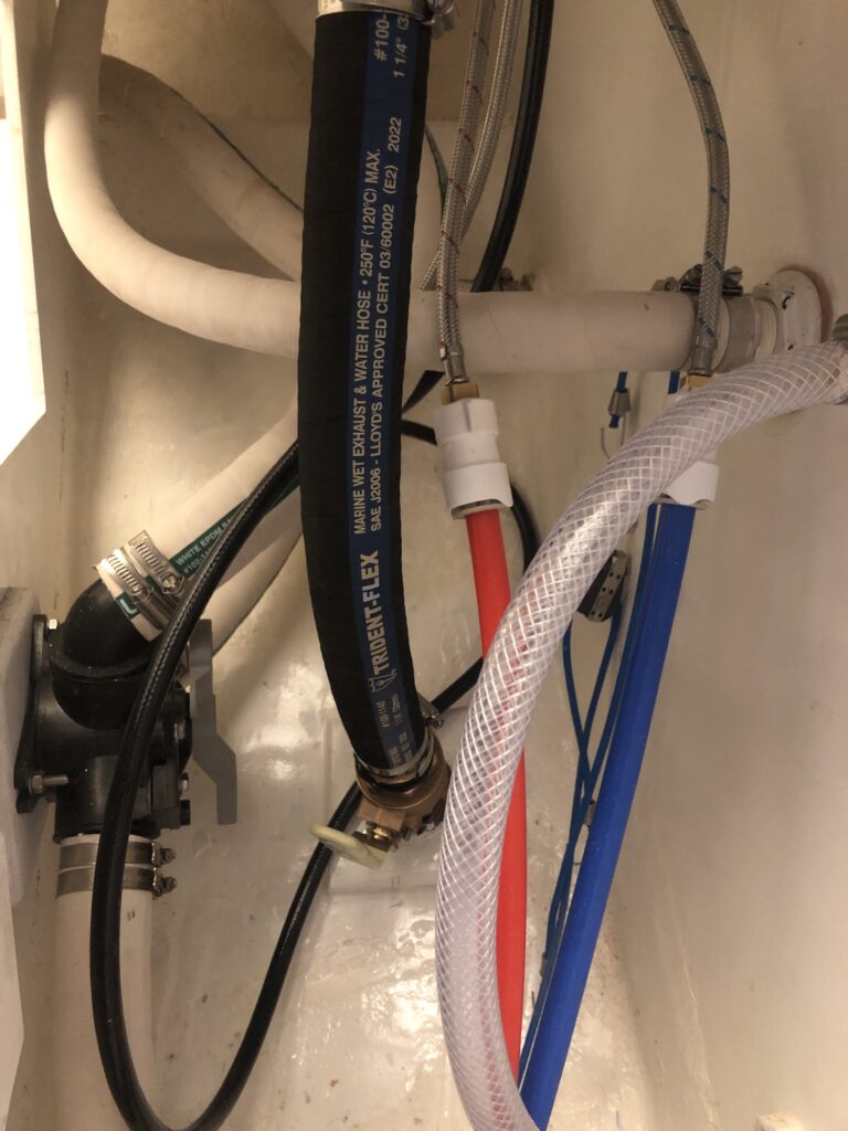
For the galley sink, I used two elbows to add a “jog” to the drain. The hose is so stiff that bending it to mate the thru hull to the sink created too much strain on the sink.
TESTING THE WATER SYSTEM
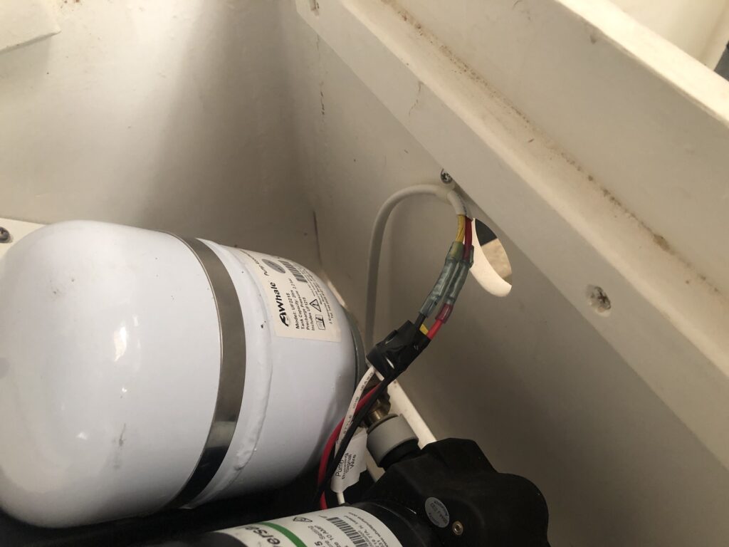
I still had a few jobs before I could test the water system. One was to wire the pump, which is now controlled by a switch on the electrical panel.
Finally, I could test the water system. Here is a video of the galley sink running the cold and hot taps. The motor noise you hear in the background is the pump, which cycles on when the pressure in the accumulator drops below a set level.
The pump runs only when water is used, and should be much quieter when the locker is covered and then the berth cushion is in place.
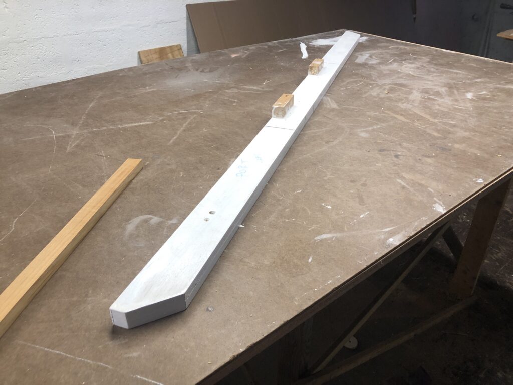
BEAM
There is a beam under the cockpit that spans the bulkheads that flank the engine. You can see the port side of it here, in this picture from a November-2022 post:
When the beam is removed I have excellent access to the back of the engine and the drivetrain. When the beam is in place, access is compromised.
The beam is easily removed when certain under-cockpit floorboards are up. One of these floorboards, however, supports the water heater, which is a semi-permanent installation. My solution to this problem began by dadoing out a wide, deep groove in the center area of the forward side of the beam:
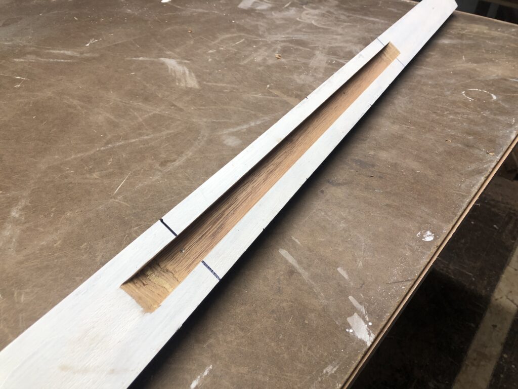
Next, I fabricated a teak “key” that would fit snugly in the groove (left side in image below):
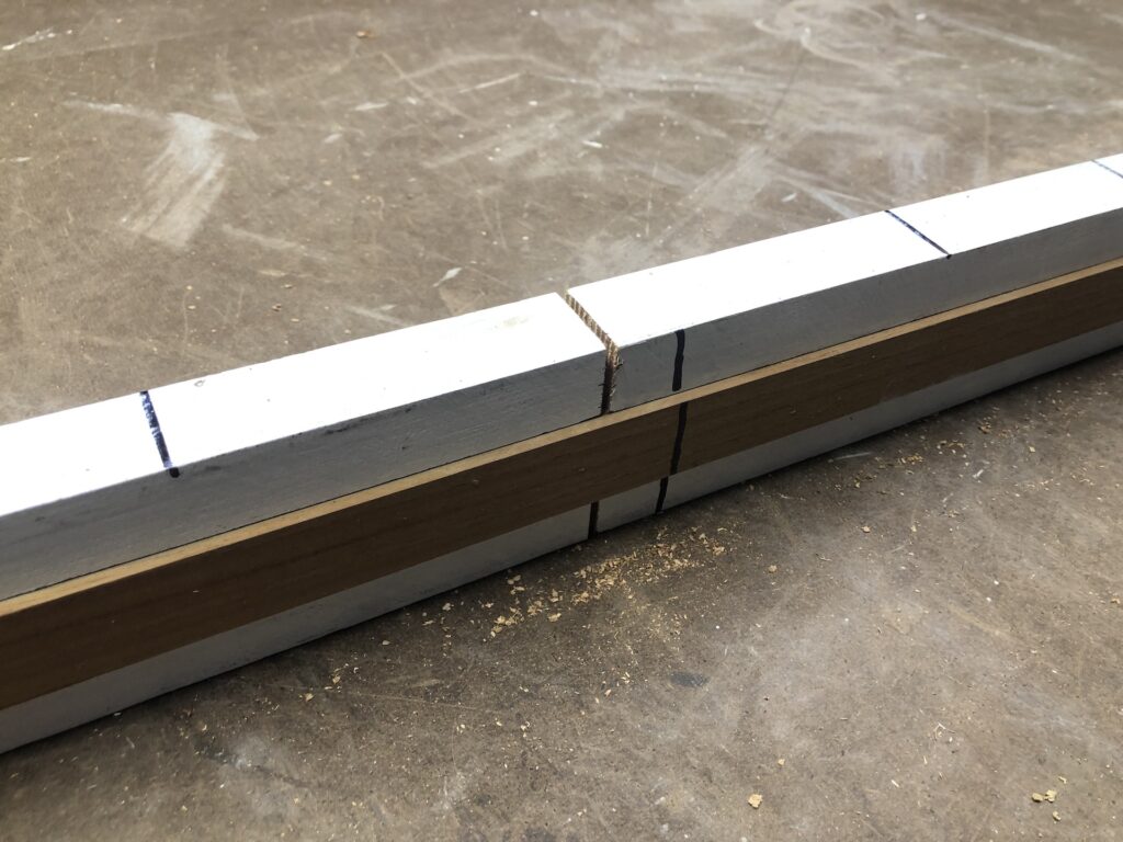
I fastened the key into place with four screws, then removed it and cut the beam in half.
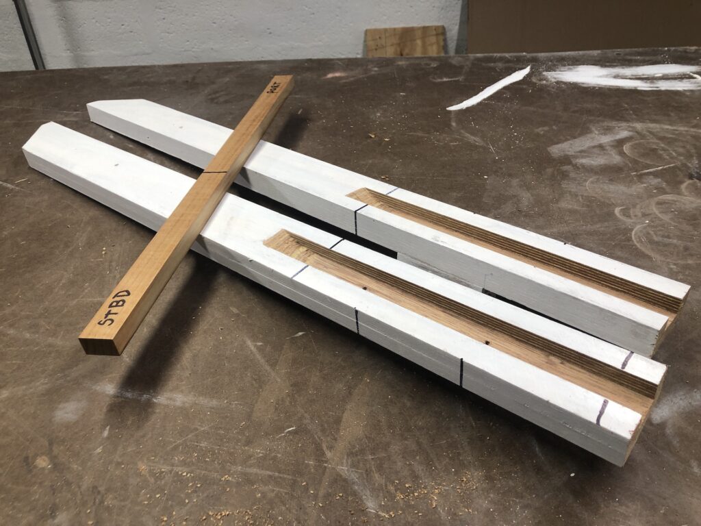
Now, upon installing the key, the beam assumes its original length exactly, and the key has plenty of strength for this application.
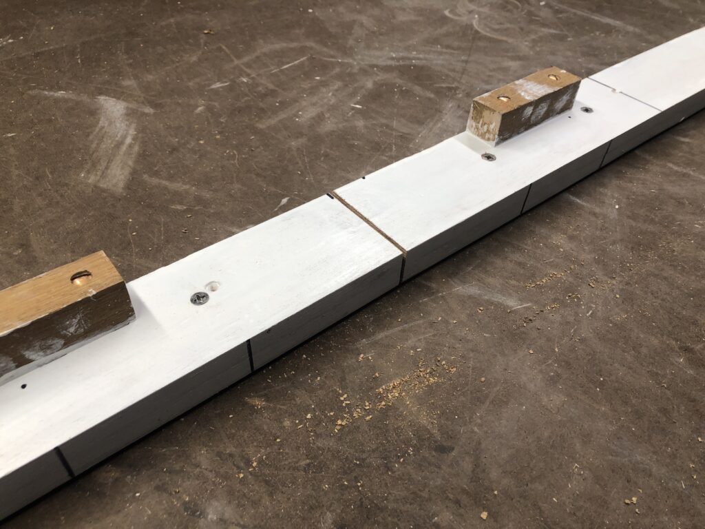
I will now be able to remove this beam without removing the water heater. Since this work created a bit of bare wood, I needed to do some painting, and decided to paint the remaining unpainted under-cockpit boards while I was at it:

PEDESTAL
Turning the boat starts with a turn of the steering wheel, which will be attached to the original steering pedestal you see below.
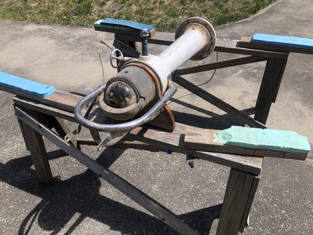
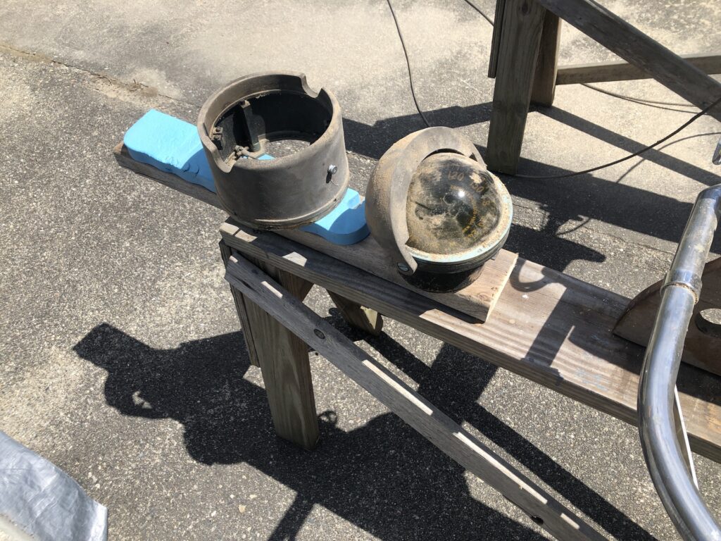
This pedestal is in fine shape, but needs some attention (mostly cosmetic). I began by removing the binnacle compass, which I’ll clean up and someday have reconditioned. For now I’ll just clean it up.
The compass sits on this teak base, and you can see from its shape that it once supported a hinged cockpit table. I’m going to replace this base with a simply circular teak base and someday consider building a cockpit table.
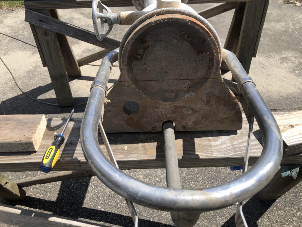
After removing as much hardware as I could, I sanded it down:
Next week’s work includes painting and installation of the pedestal.