12/14/22: Chainplates, Stem Fitting, Panel and Frame
Chainplates on a sailboat are stainless-steel plates that protrude through the deck and support the standing rigging (shrouds and stays). RUCKLE has 14 chainplates. The mainmast is supported side-to-side by six shrouds, and the corresponding chainplates are fastened to chainplate knees that hide behind cabinetry in the main salon and head.
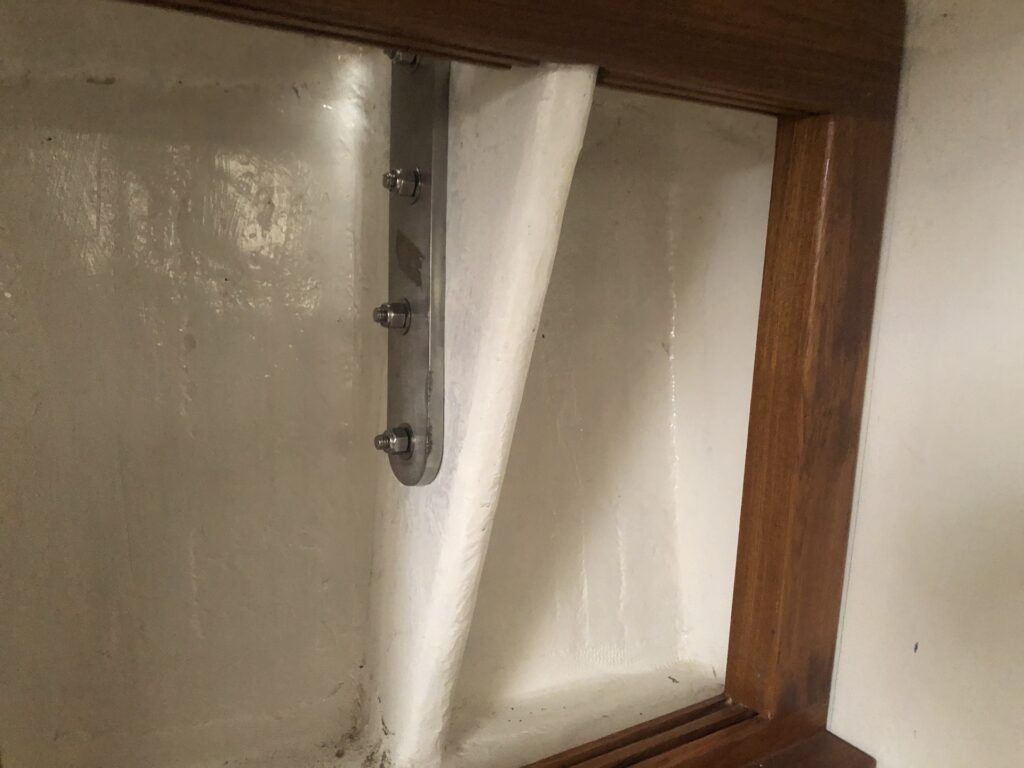
Here are the top-ends of the three port-side mainmast chainplates:
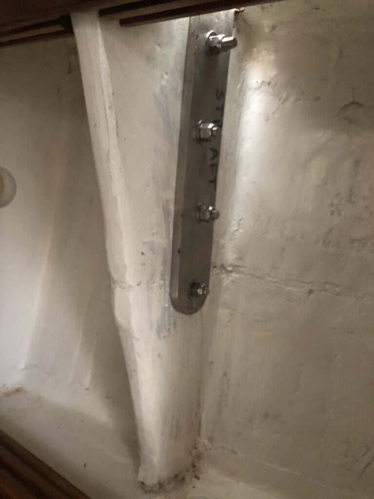
Similarly, there are six chainplates that prevent the mizzen mast from moving both fore-and-aft and side-to-side. These are those on the starboard side:
The mizzen mast has no dedicated backstay or forestay, but has two so-called “runners” (more on those another time).
The mainmast has double backstays that are supported by the two chainplates. Here is the port-side backstay chainplate:
The last task related to chainplates is bedding them above deck to make a watertight seal (more on that another time).
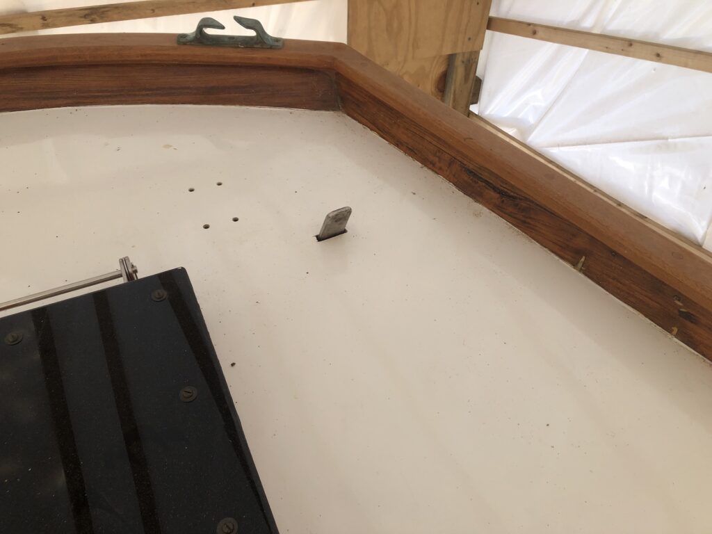
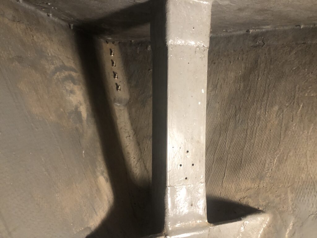
Double forestays prevent the mainmast from falling backwards and are supported by the stem fitting you see here:
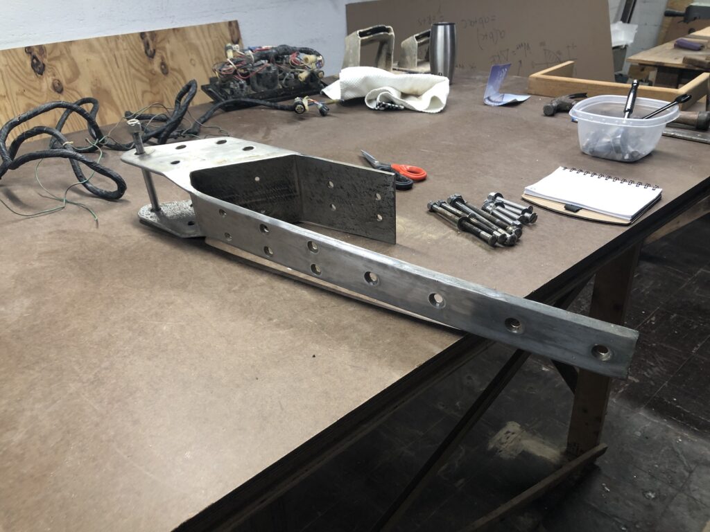
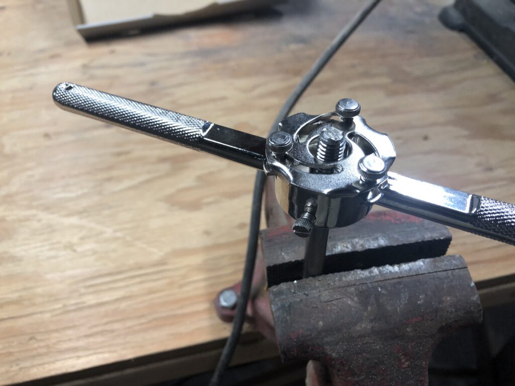
Eight bolts secure the stem fitting (as well as four screw, which I suspect provide no additional security). You can see the bolts in the image above. Four shorter bolts are new and they pass through glass and the nuts are tightened from the anchor locker. There are four longer bolts that pass through teak and are secured from on deck to the short flange. The threads on the long bolts were damaged (from removing them years ago, no doubt), but I was able to clean them up with a die:
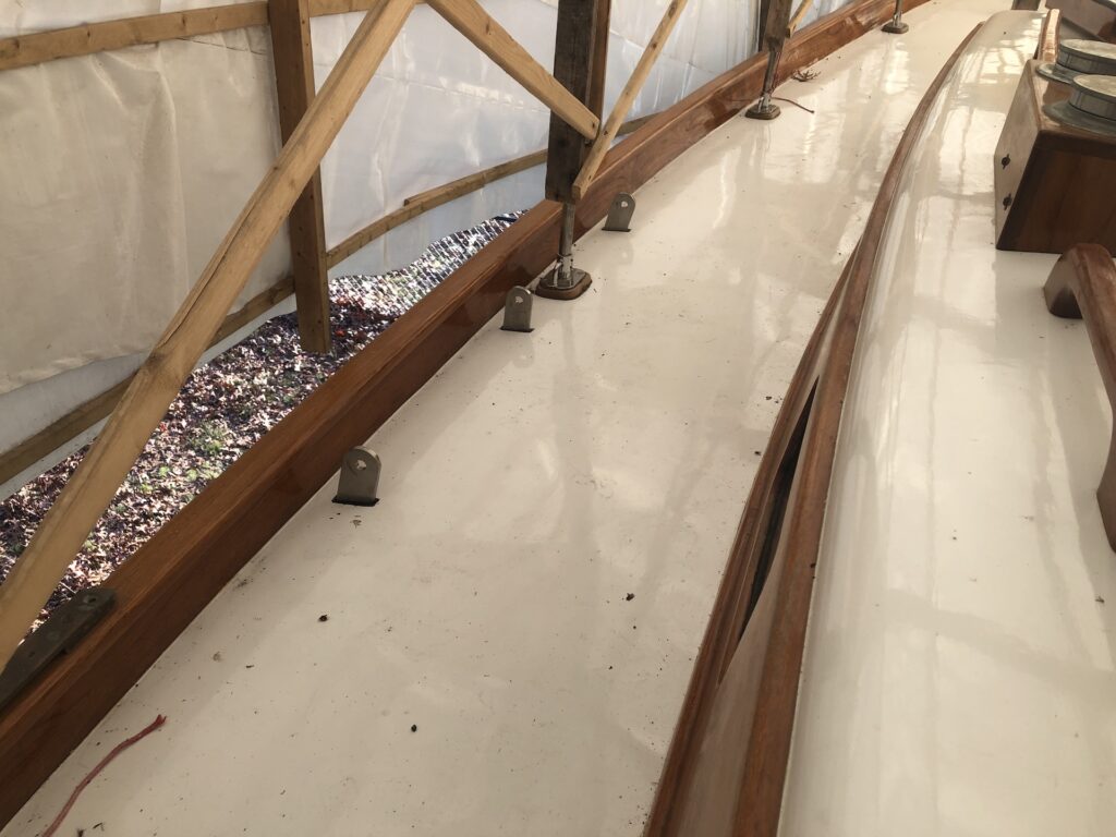
Here is the stem before installing the stem fitting:

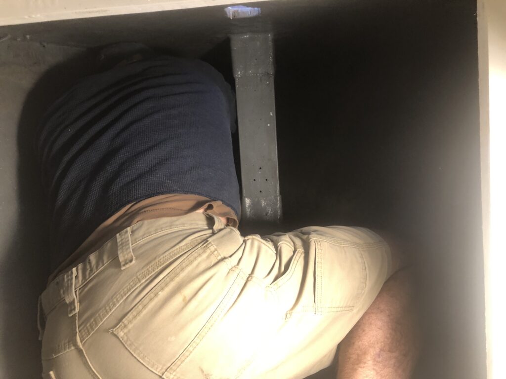
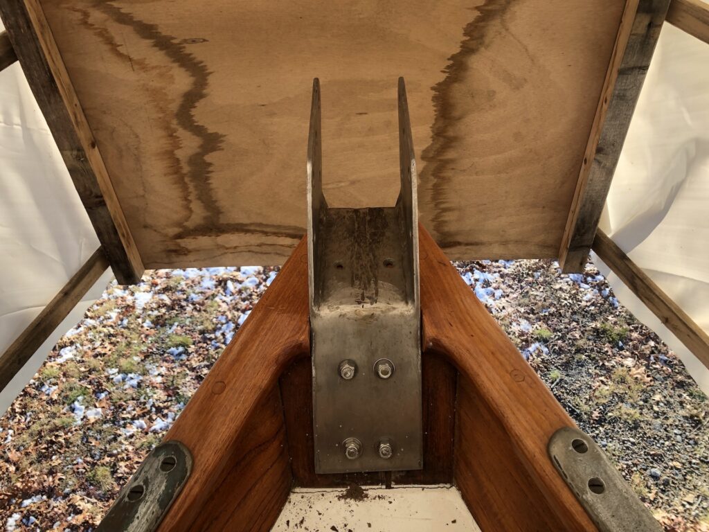
I bedded the fitting with marine caulk where it met fiberglass. With a trusty assistant and a big flat-head screwdriver on the outside, I tightened the nuts from the inside:
And then on deck:
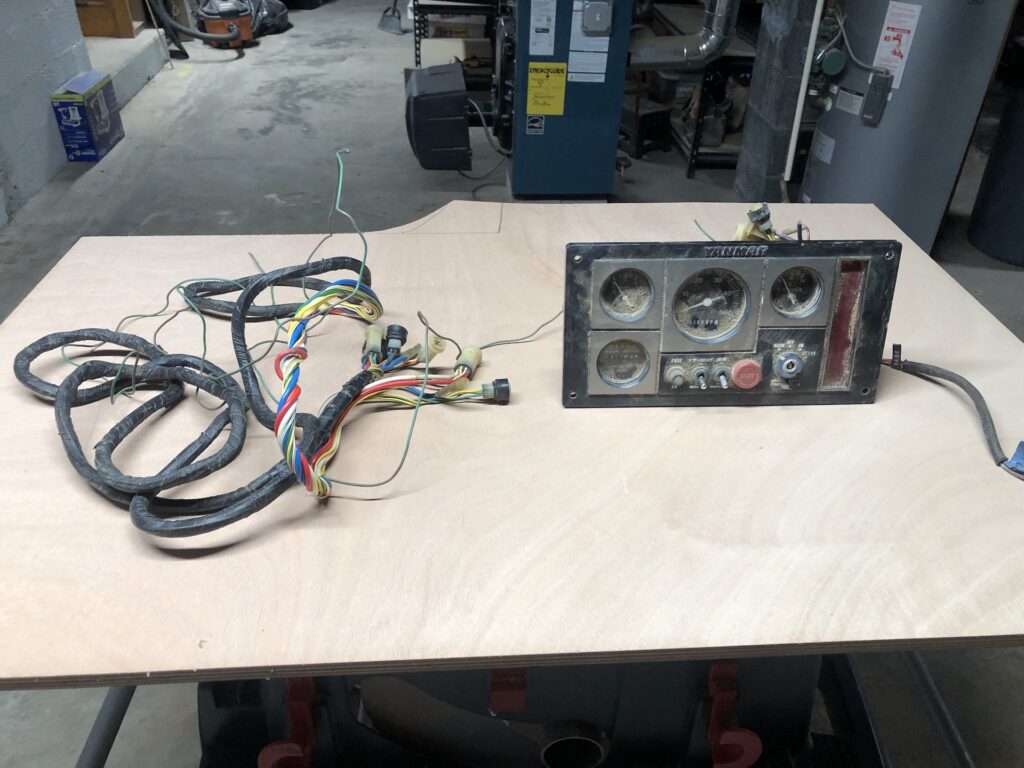
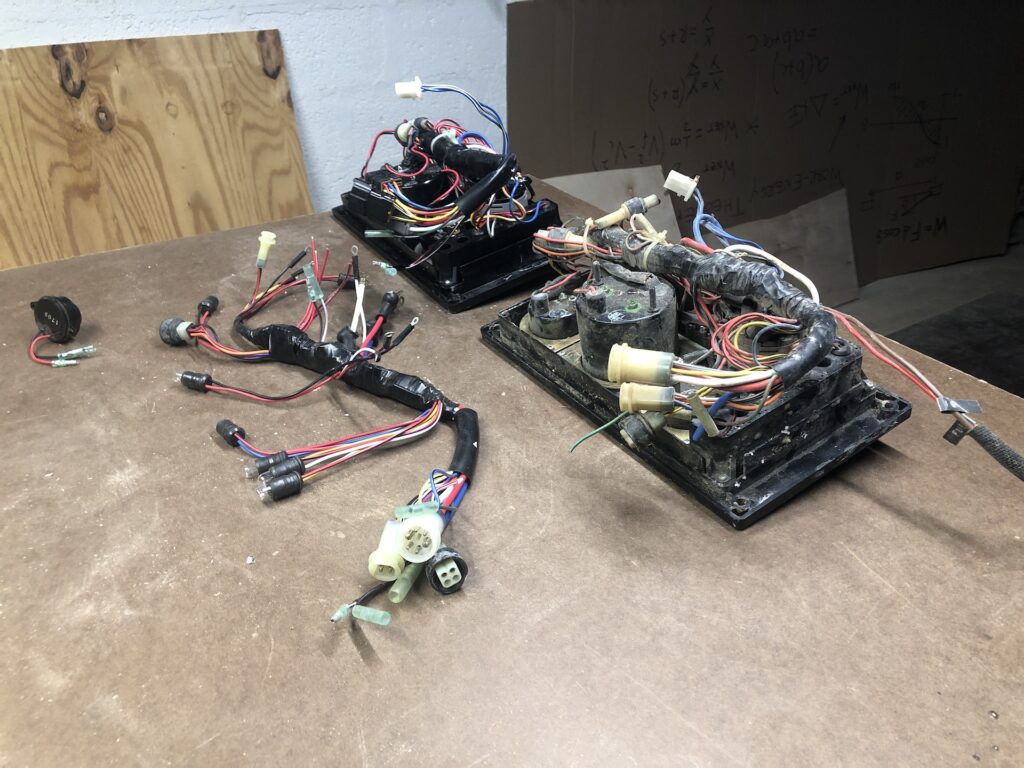
Meanwhile, the engine panel got some attention. The image below shows the original panel (right) and the wire cluster (or “electrical umbilical cord”, if you will) that connects the panel wire harness to the engine (left).
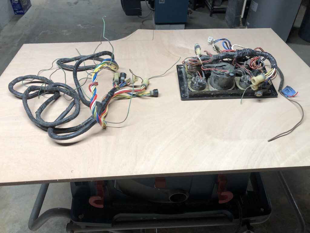
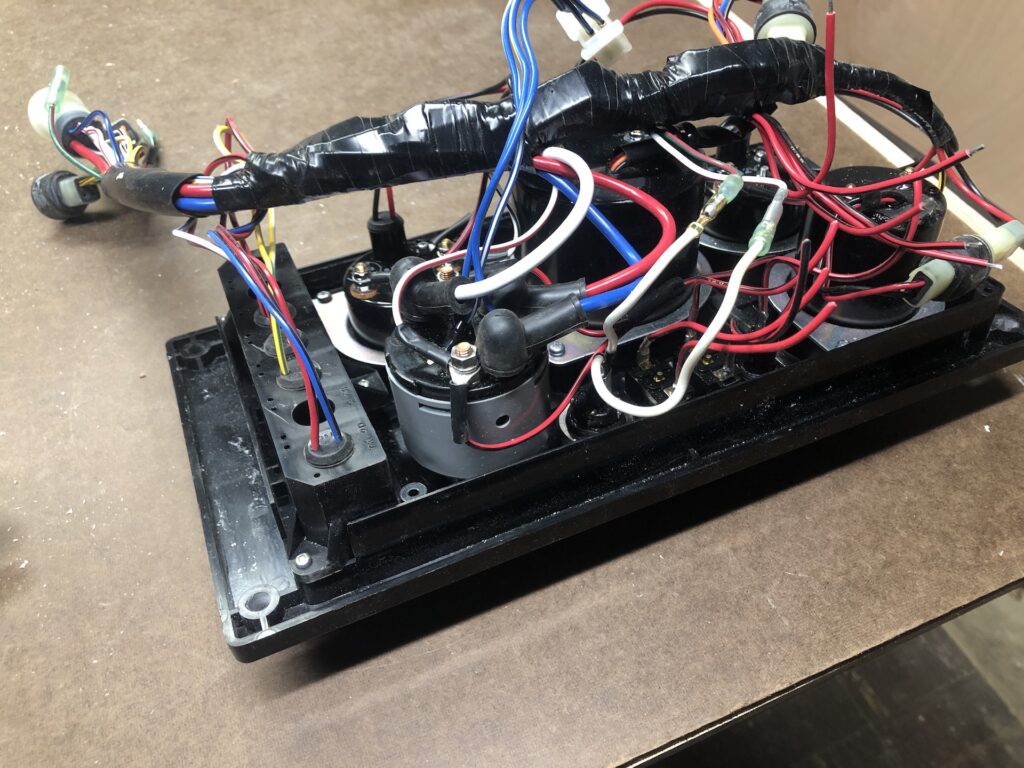
You can see the wire harness now that I’ve turned over the panel to expose its backside:
A few years ago my systems guy recommended a new panel, and so I purchased one. It didn’t come with the umbilical cord, so I ordered one separately afterwards. When it arrived I was shocked that it was so short, and contacted the company to try to get a longer one. I never resolved the situation, and moved on to other projects. That was about two to three years ago.
In the last few weeks I’ve been back to thinking about the panel. As it turns out, the too-short umbilical cord was actually a new harness. In fact, I got lucky because connections to the harness on the new panel don’t match my old umbilical cord. Somehow, through my confusion, the company was able to determine that I needed something and sell it to me.
The image below shows my new panel (top) and the original panel (bottom) and the new harness (left).
Using the original panel as a guide, I was able to swap in the new harness to the new panel in about 30 minutes, and here is the result:
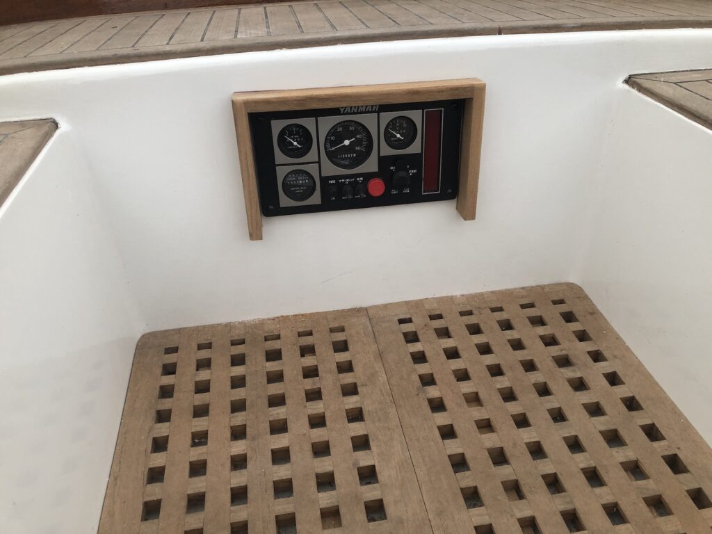
About two years ago, you got a glimpse of the new panel in THIS POST, as well as the corresponding teak frame. I decided to locate the new panel/frame in roughly the same place as the original–in the front end of the cockpit. The logic for doing so deals with visibility for the helmsman and proximity to the engine.
The hole was carefully cut and the frame was fastened with bronze screws and bedded with thickened epoxy:

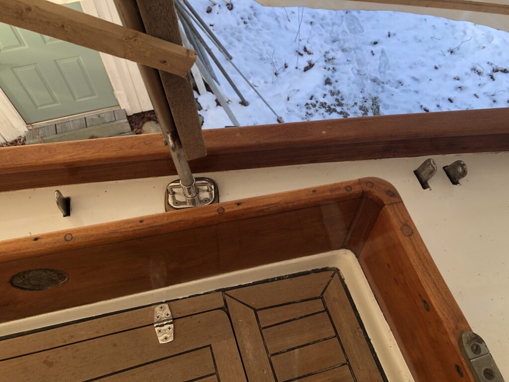
The panel was then installed:
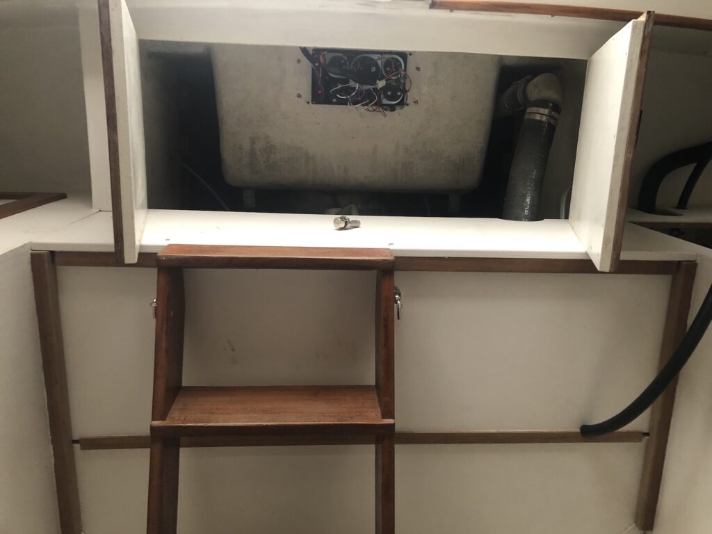
A plexiglass cover that swings on a piano hinge will protect the panel from spray and feet. As seen from the galley:
Tom Heald
12/15/2022 — 12:30 am
Mike Great work . Tom
Trish
12/15/2022 — 1:11 am
Looks super-complicated, Mike! Nice job!
Kath
12/15/2022 — 7:19 pm
Fantastic work, Mike! So exciting!