3/26/23: Head Plumbing, Engine
HEAD PLUMBING
I built the integral holding tank in Summer 2016 (click HERE for a review of some of that work). Tank ventilation allows out-gassing when filling while pumping the toilet, and in-gassing when the tank is being emptied. Moreover, a well-ventilated tank permits plenty of air circulation. This CRUISING WORLD ARTICLE explains the importance: “Two kinds of bacteria inhabit holding tanks: aerobic and anaerobic. The former require oxygen to exist and reproduce; without it, they’re goners. Aerobic bacteria break down organic matter, creating as a byproduct carbon dioxide, which is odorless. Conversely, anaerobic bacteria thrive in a low- or no-oxygen environment. The byproduct they create is a variety of gases, including sulfur monoxide and sulfur dioxide. which impart the pungent odor (and methane and carbon dioxide, which are odorless).“
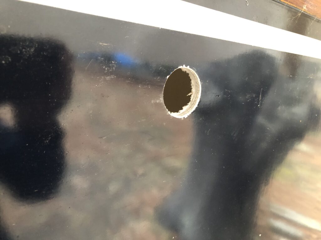
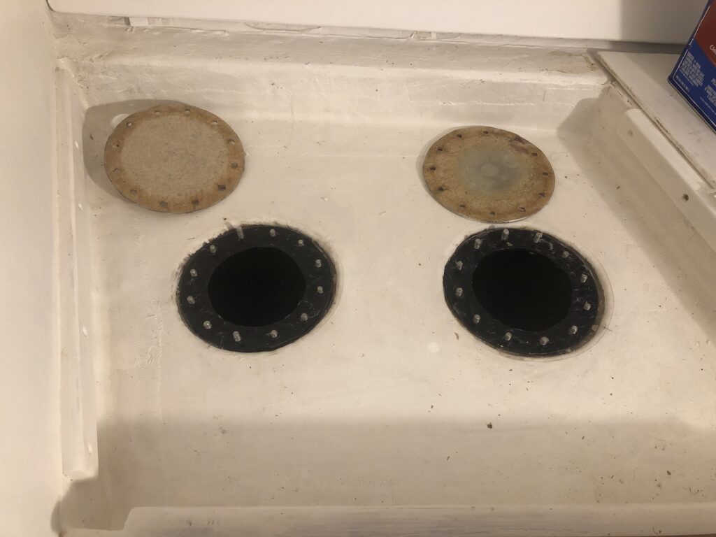
I originally installed two 1-inch vents in the top of the tank, but leading hoses from the top of the tank would have been problematic. So last week I plugged those vents and installed new vents in the fore and aft ends of the tank. The vent hoses typically lead to the cabin house or topsides. I decided that topsides would be a better choice both aesthetically and practically. Here is a hole on the port side, just under the cove stripe:
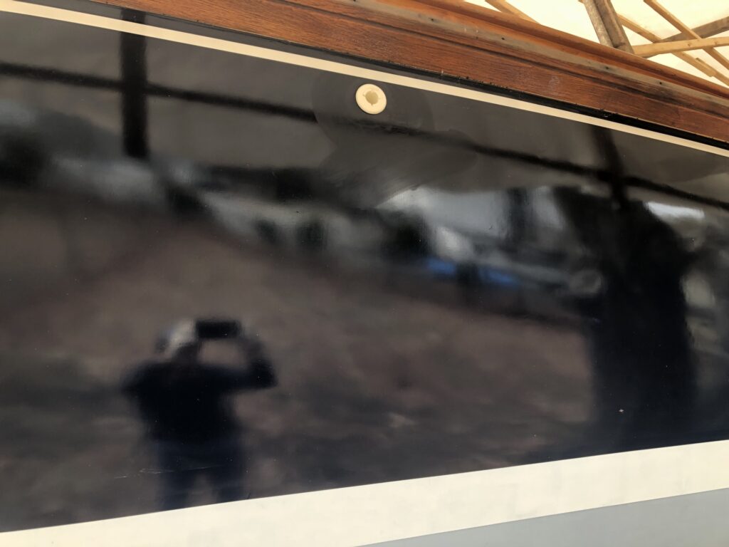
Here the thru-hull is bedded:
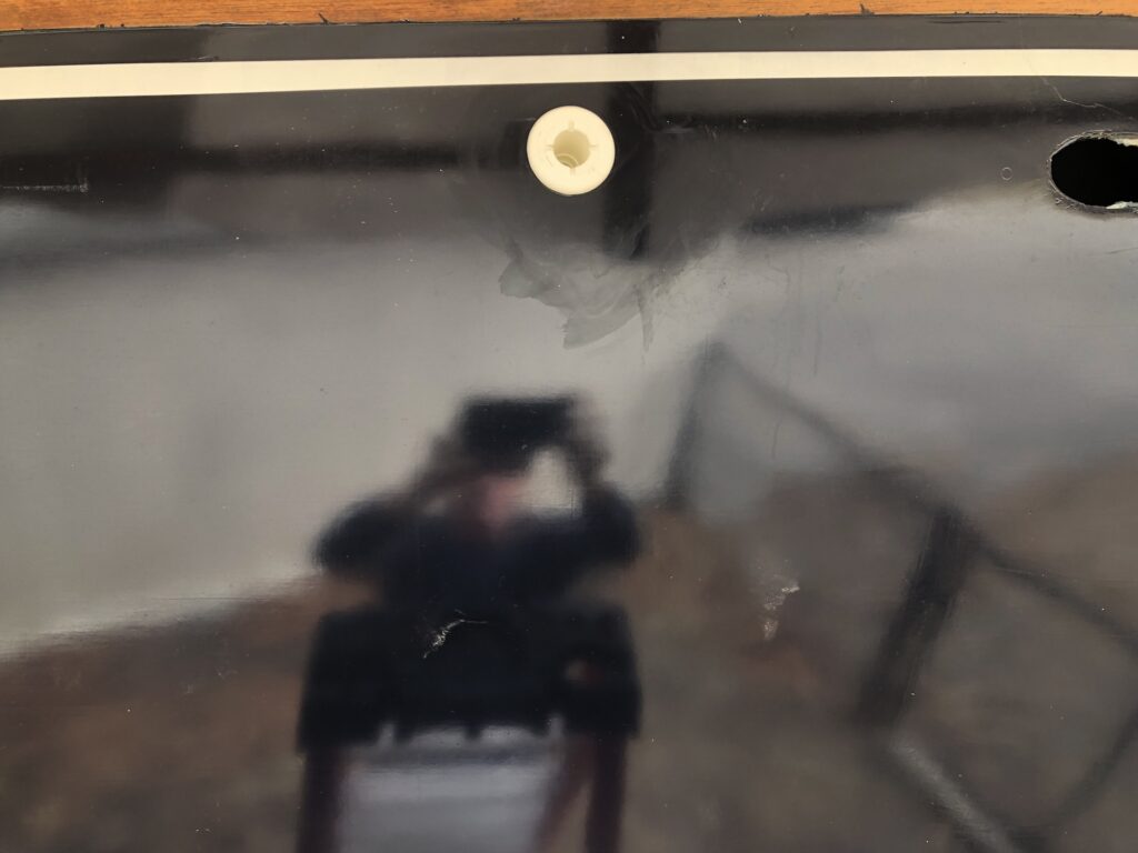
The second thru-hull was installed on the starboard side, closer to the bow (note the hole where navigation lights will be installed):
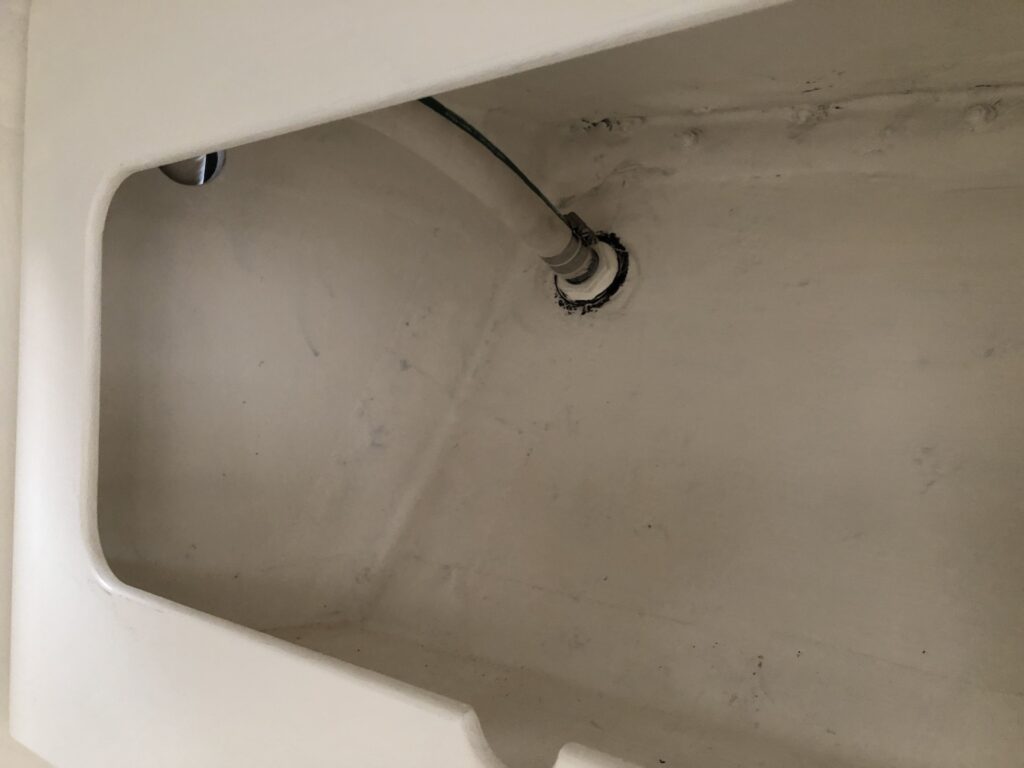
This is the new vent running off the front of the tank:
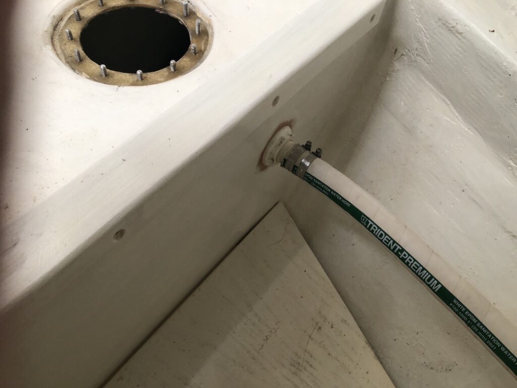
The hose runs forward, always uphill, and into the chain locker.
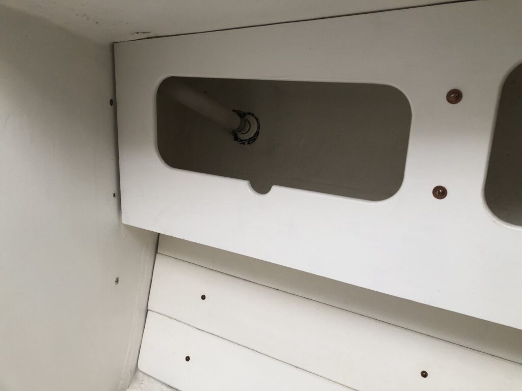
And now back from the chain locker and out the starboard topsides:
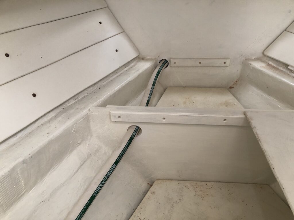
The other vent runs off the aft end of the tank (under the head sink) and forward, through a bulkhead, and out the topsides on the port side:
In both cases, the highest point of the hose runs are just under the deck and as inboard as possible. Those points are, hopefully, sufficiently above the level of the heeled waterline that I won’t have to install shut-off valves for certain sailing conditions. We’ll see.
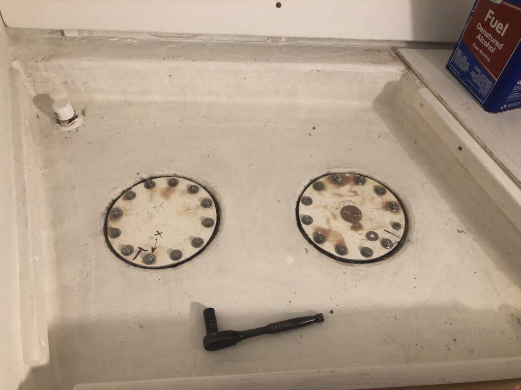
Hopefully I won’t have to open the tank again for a while, so I lubed the gaskets and closed it up:

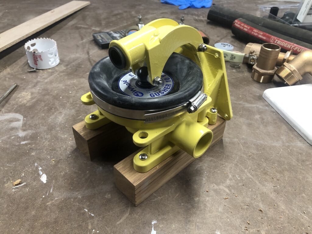
This is a WHALE GUSHER manual pump. It is a powerful, high-capacity pump and I now have three. Two new, and one old. One of the new pumps will be for emptying the holding tank into the ocean.
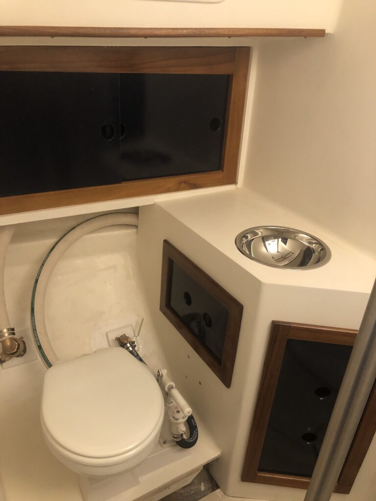
There were two choices for installation location: (1) Under the cabinet shelf, bolted upside down, or (2) inside the cabinet in an upright position. The following image illustrates my choice:
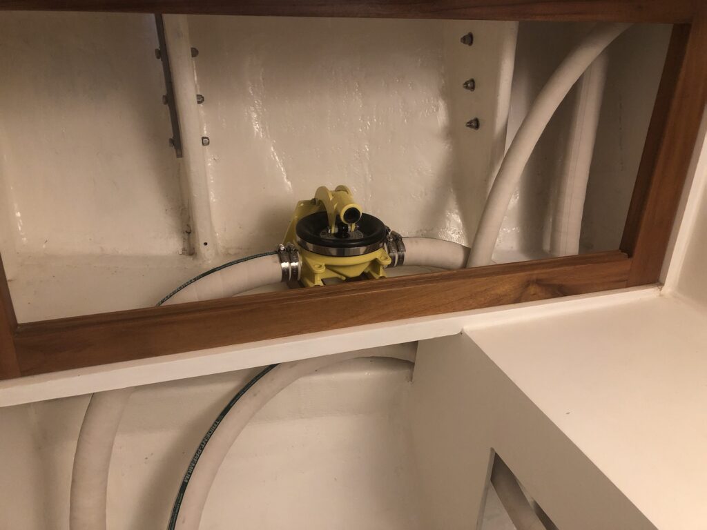
There’s still plenty of room in there for shelves and storage. There are two hoses in the cabinet NOT connected to the pump. The smaller hose is the port-side vent, and the larger leads to the pump-out fitting on deck.
The under-sink space is busy and will not be used for storage.
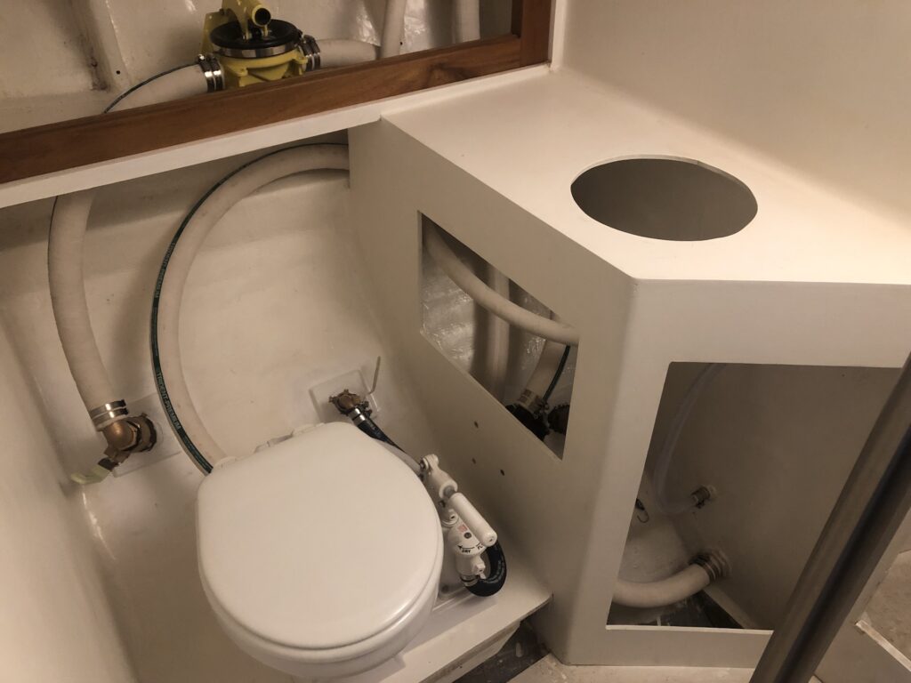
The image below gives a closer look. The Y-valve setting chooses deck pump-out versus overboard pump-out. The thru-hull is for the sink drain. The clear hose is the level gauge and the only non-sanitation hose used in the system. Time will tell if it is permeable enough to odor to require regular changing, or a different approach altogether. (The bungee cords and blocks are currently how the doors are held in place.)
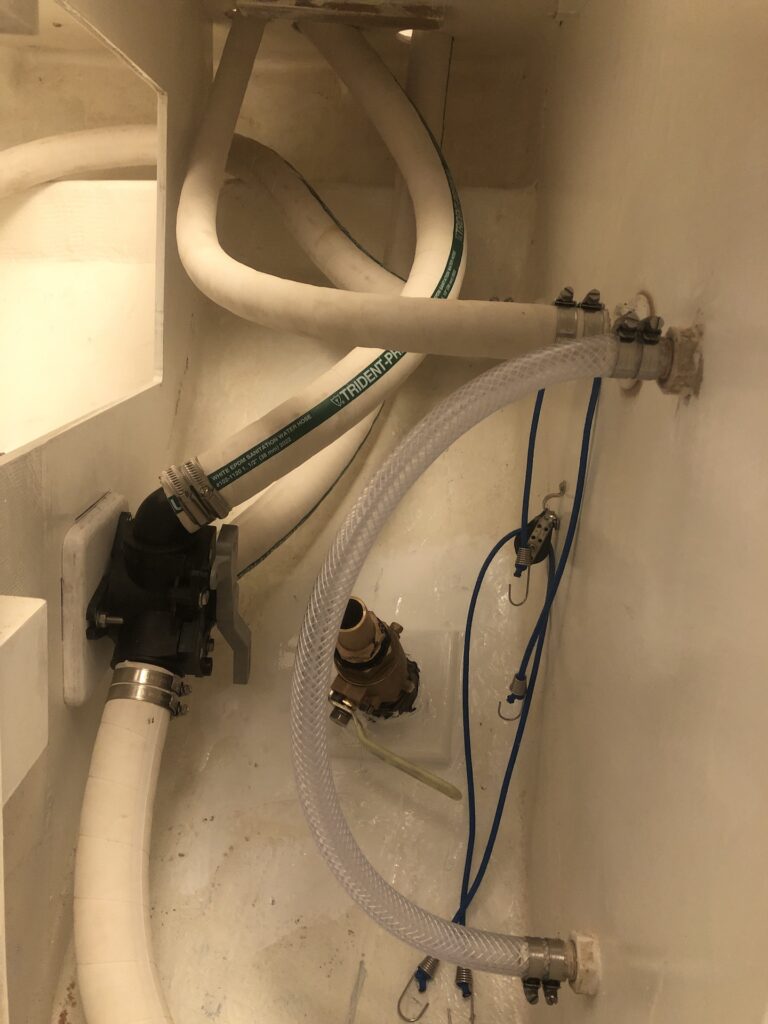
My mistake. The 3/4-inch black hose in the image below is also not sanitation hose, and doesn’t have to be. It leads seawater to the head.
ENGINE
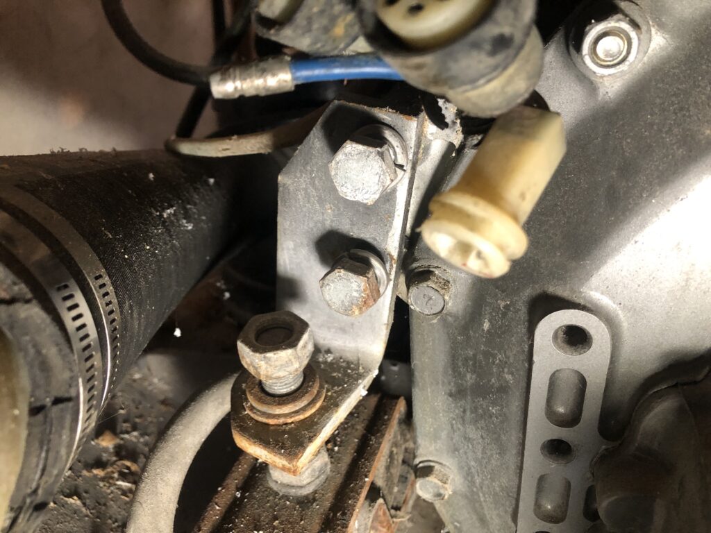
Between visits from my mechanical/electrical guy, I sometimes have prep work to do for the next visit. Three heavy electrical cables that we will be replacing are still connected to the to the engine. Two are bolted to the back end of the engine, so I climbed under the cockpit for a look. I found the connections for the panel harness, which, in the image below, is obscuring the two large bolts I had to remove.
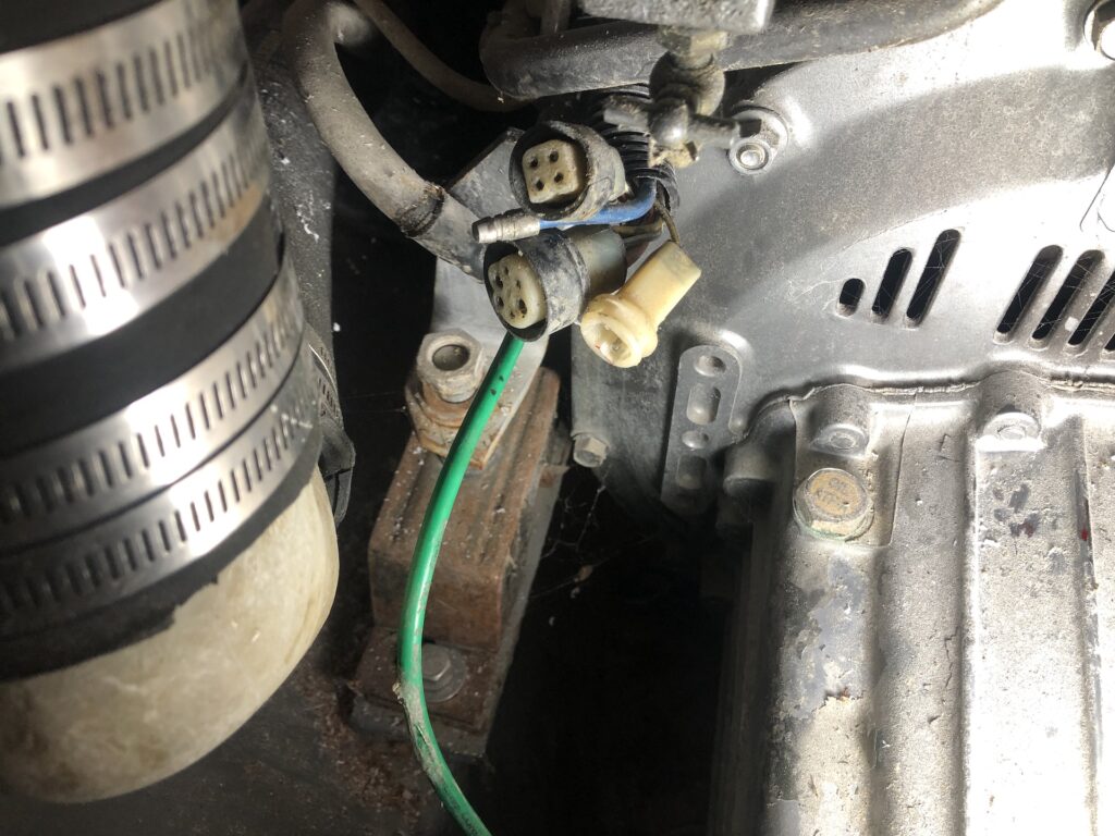
I was initially unable to move the bolts, but I recruited some torque in the form of a bronze pipe:
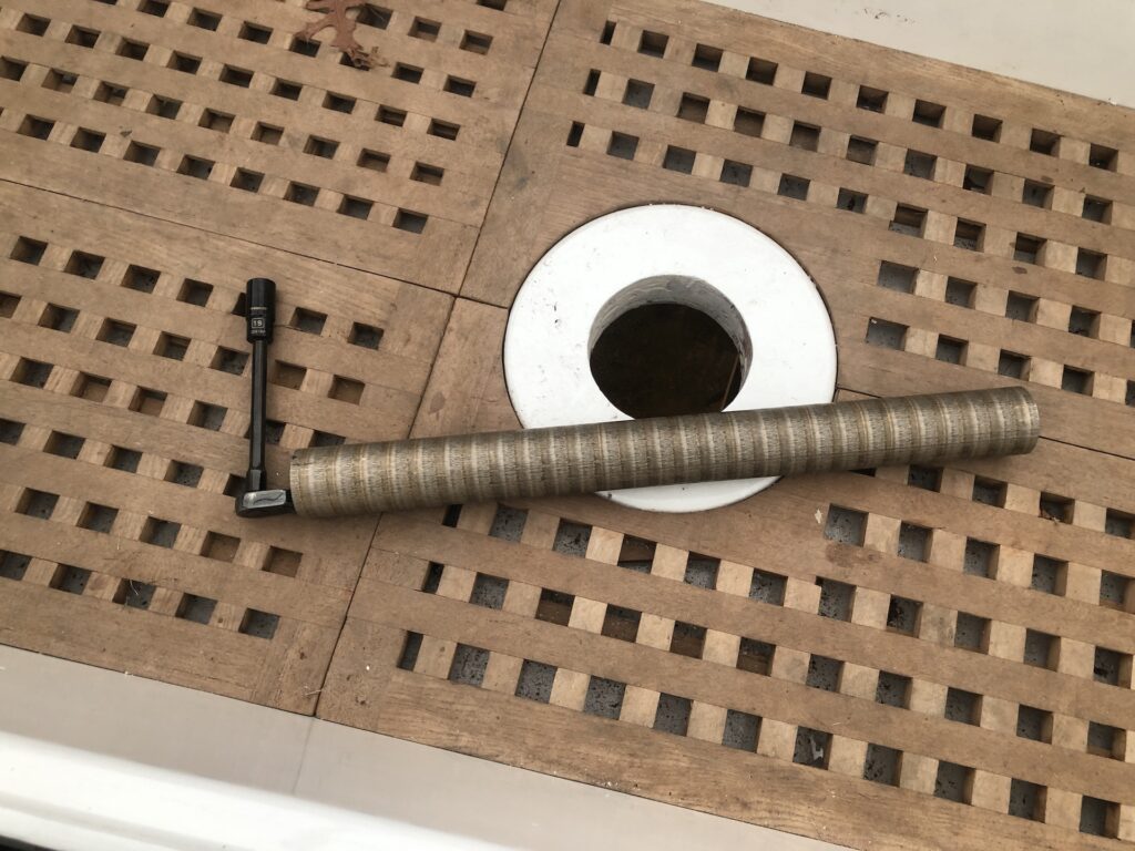
There was one cable under each bolt, so I removed both bolts. Upon removing the second bolt, the engine shifted and I knew I had made a mistake. These bolts connect the motor to the motor mount. Now the bolts and holes were not aligned, and I had to jack up the engine to fix my mistake:
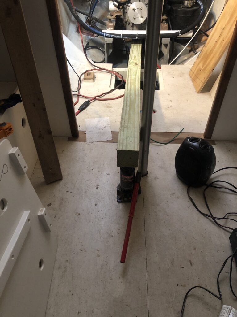
It could have been worse. I got the bolts back in the holes and tightened them just after taking this picture:
The front of the engine has also been getting attention. On the left in the image below you can see the raw water strainer, which filters out stuff like seaweed from the cooling water. On the right is the primary fuel filter.
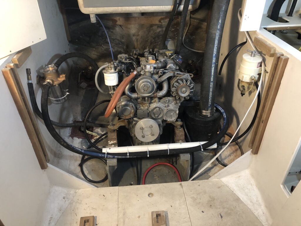
Just outboard and to port is fuel tank deck fill. The tank vent leads back into the engine compartment and to the cockpit.
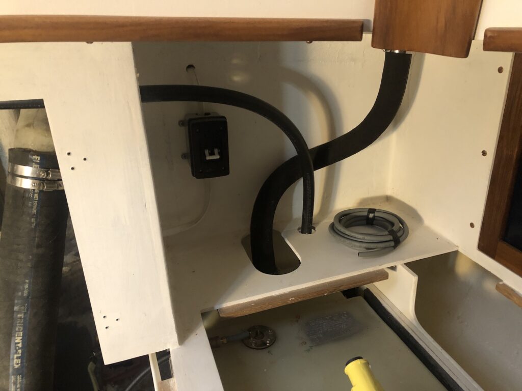
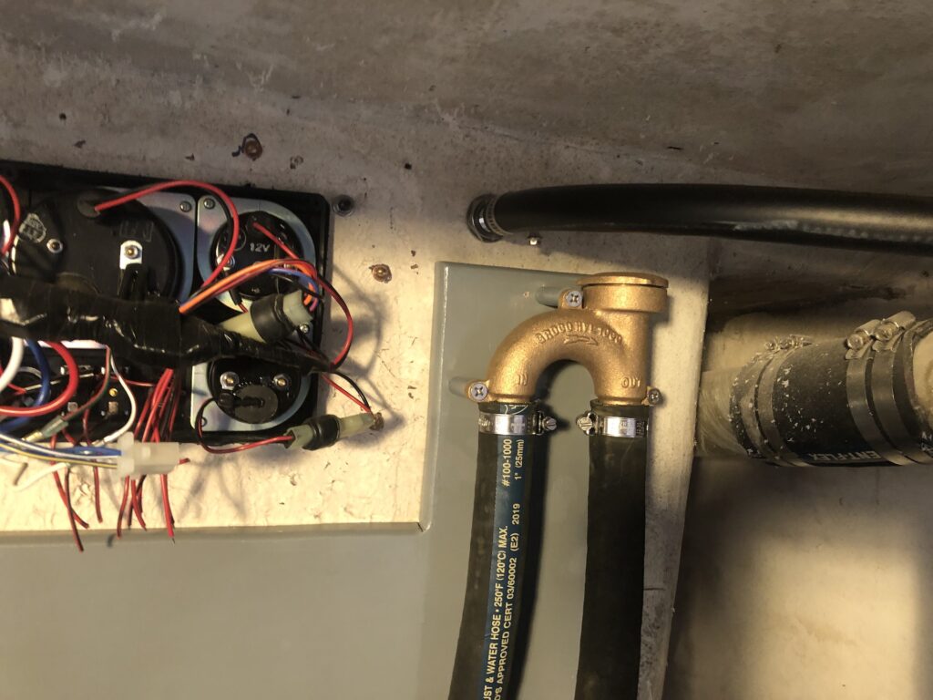
The image below shows the fuel-tank vent running to the cockpit. Just under it is a new bronze vented loop, which replaces its homemade predecessor.
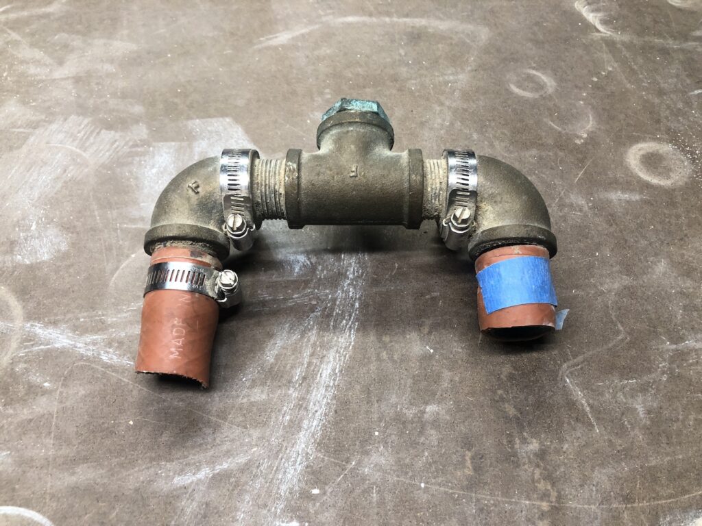
The homemade predecessor:
Mom
03/26/2023 — 7:01 pm
Whew!!