8/3/17: Galley
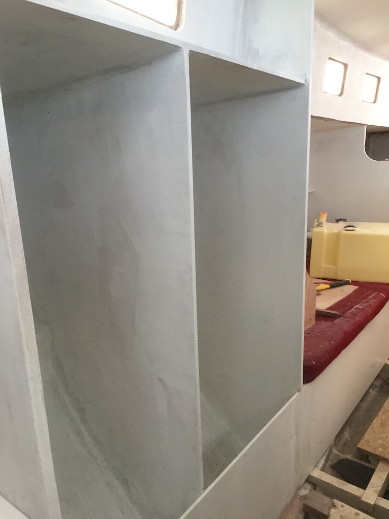
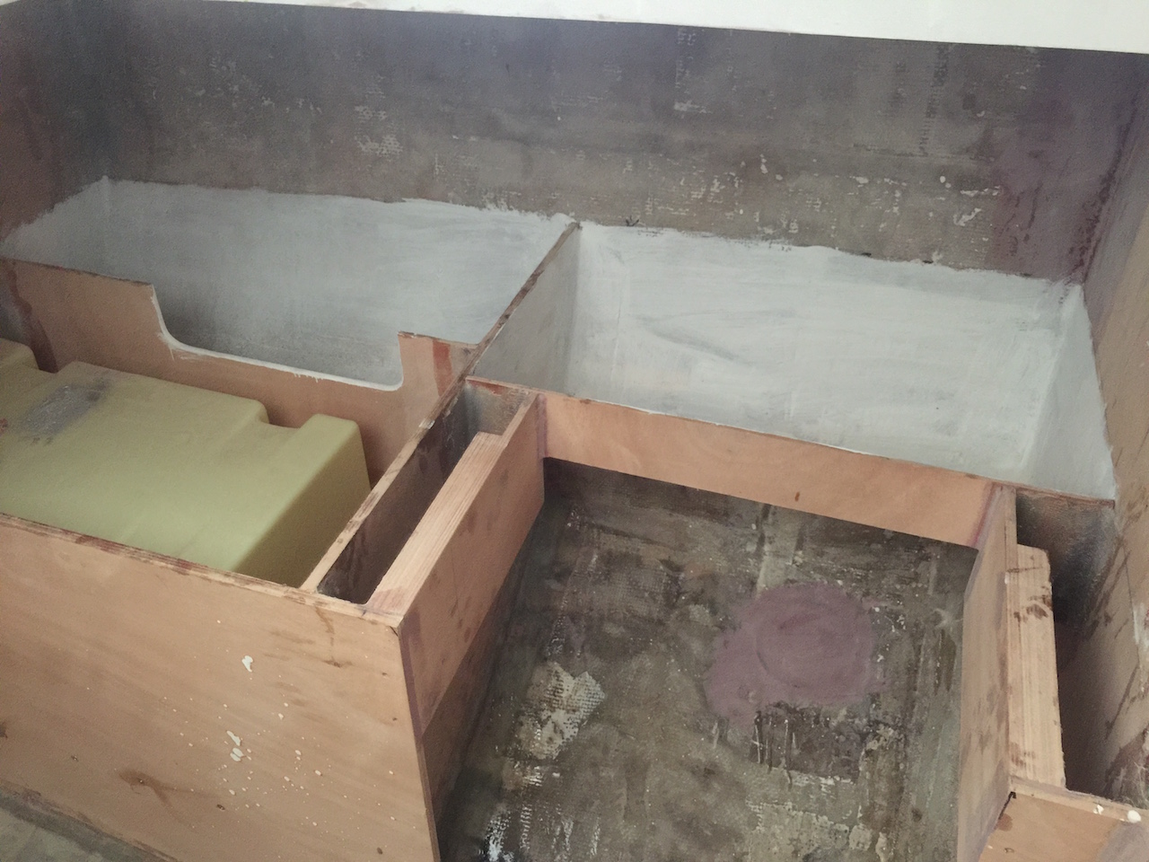
The following photos show sections the head area after one coat of primer.
Moving forward, my strategy in the cabin is as follows:
(1) Finish all jobs that require heavy grinding/sanding, or fiberglass/epoxy work.
(2) Install the fill/drain and level indicator hardware on the sub-floor water tanks, then clean out the tanks and install the lids with gaskets. Temporarily plug any openings to prevent anything from getting into the tanks before final plumbing.
(3) Design and install cabin sole.
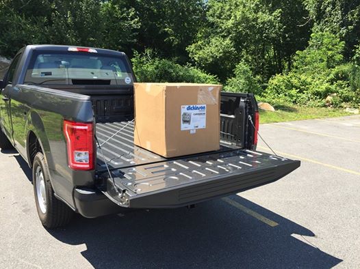
Before proceeding with item (1), I made the final decision on the stove/oven vs. cooktop debate–settling on a Dickinson two-burner propane stove/oven.
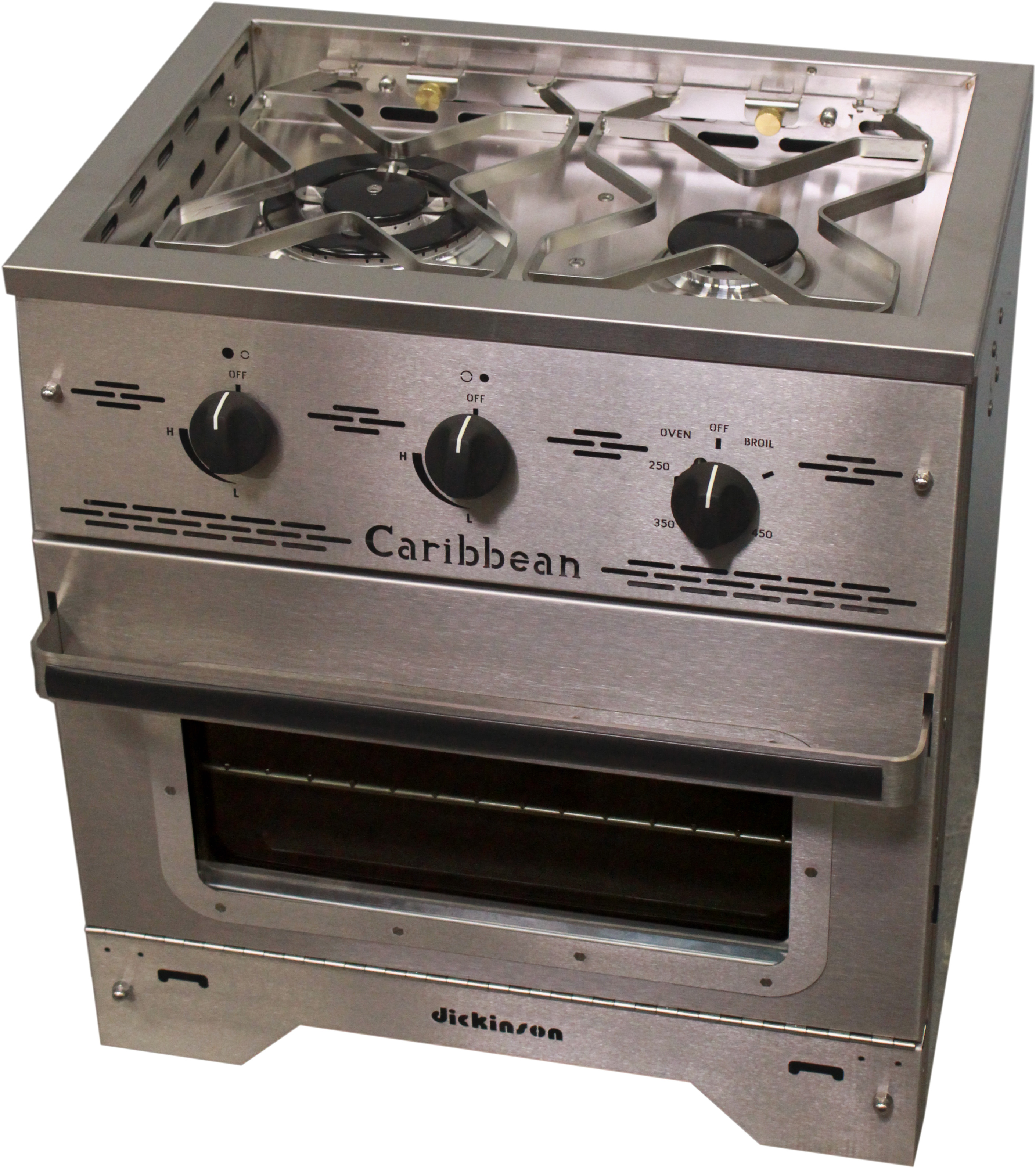
The two-burner model is about the same price as the three-burner model, but not as wide, allowing for more storage room outboard of the stove.
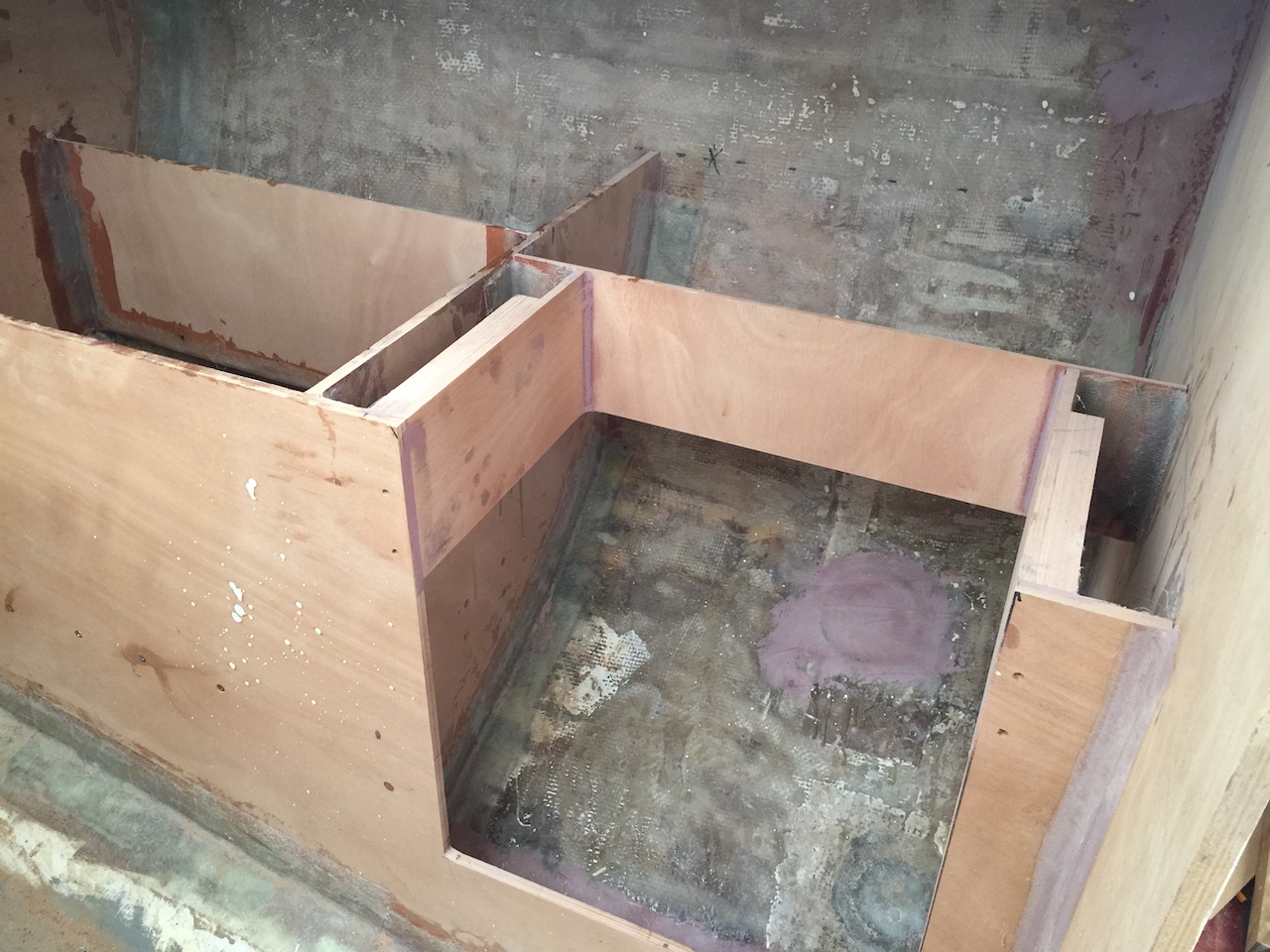
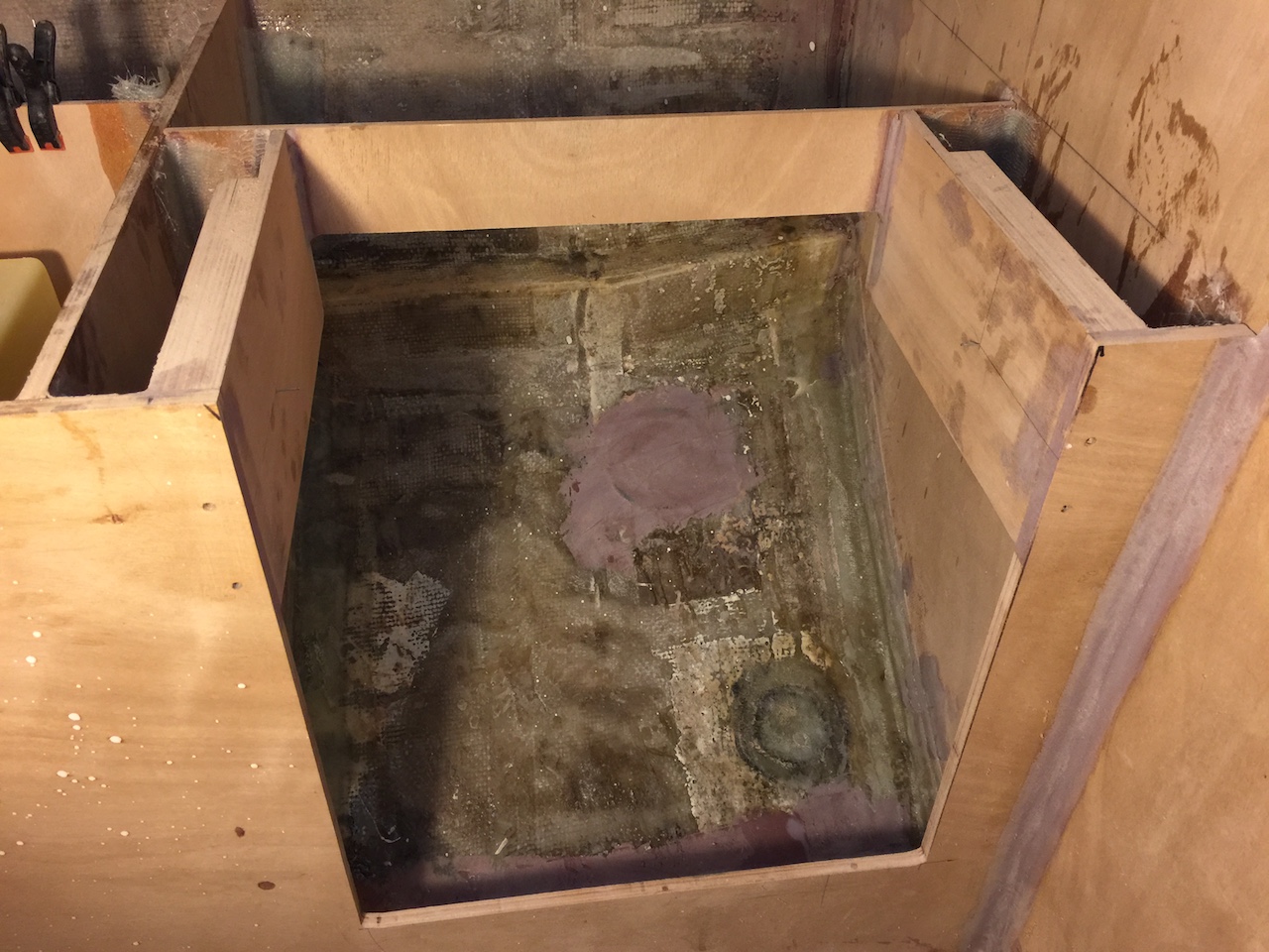
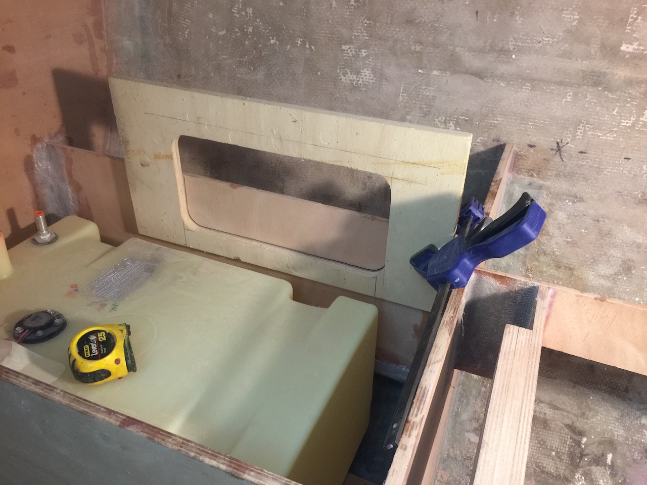
The port side of the galley concerns item (1), and the following photo shows that area, including the new fuel tank, which will be installed aft of the stove.
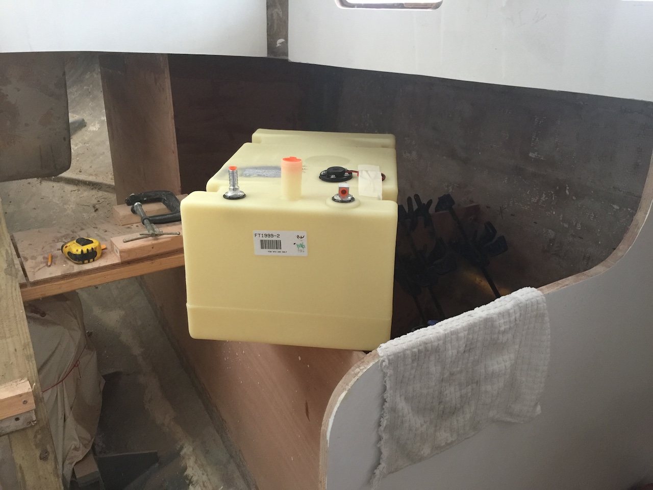
To begin, I cut out an opening for the gimbaled stove. The exact distance between the outside of the two gimbal mounts is 22 inches. After cutting out the rough shape with the jig saw, I used the router to trim to the exact width.
This new opening facilitated work on the fuel-tank supports. The fuel tank is a Moeller Marine product, and came complete with all of the required fittings, including a level gauge and sender unit. The capacity of the tank is 19 gallons. The density of diesel fuel is about 7 lb/gal, so a full tank will contain about 130 lbs of fuel, and a sturdy support structure must be built. As the tank is rectangular, and the hull is curved, I had to create some beams to support it. I started with some old oak beams that were the original floor beams.
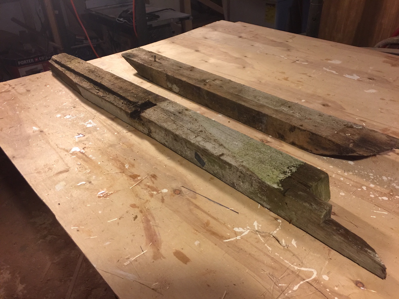
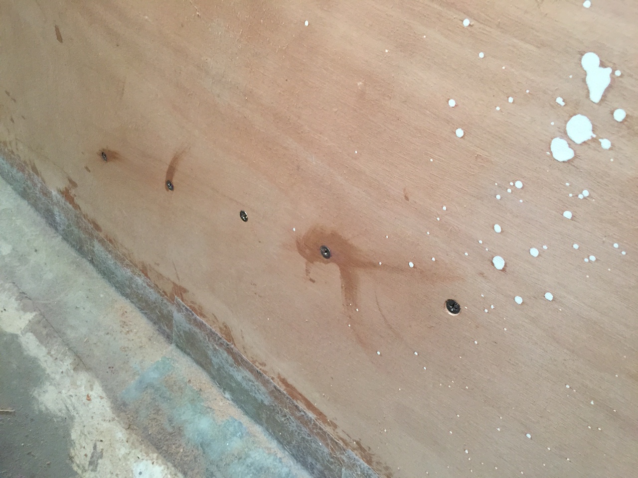
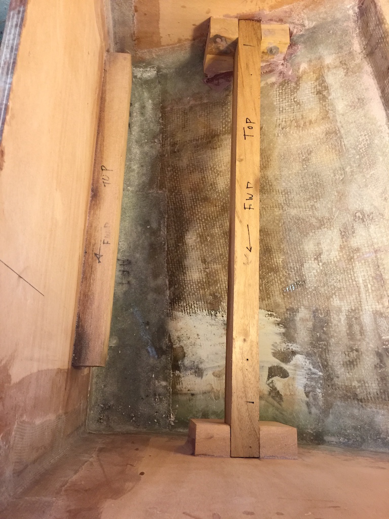
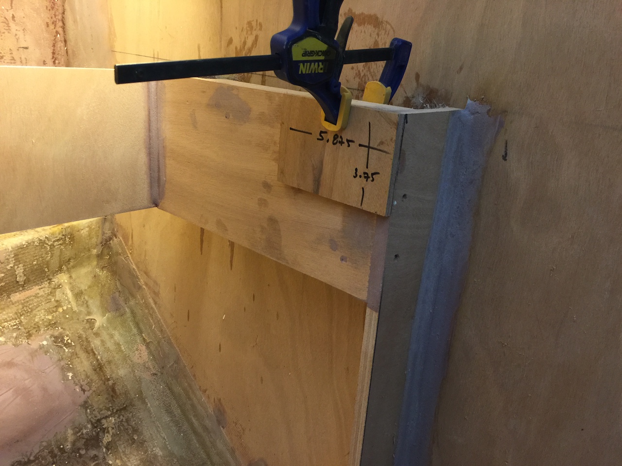
I cleaned these beams up with the planer and the table saw. One beam I installed along the fore-aft bulked that defines the port side of the engine room. The following photo shows my technique for making it horizontal.
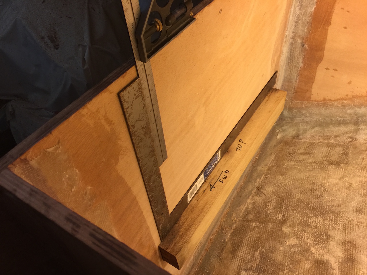
I used epoxy and five screws to secure the beam, as well as a fillet of thickened epoxy and tabbing as support below the beam. The following photo shows the screw heads as seen from the engine room.
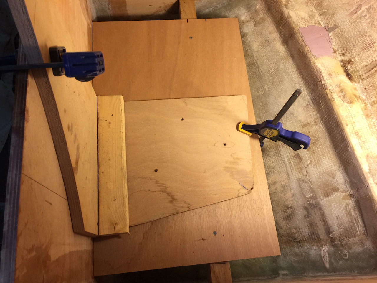
In the following photo I am using an old “right angle” jig and a piece of plywood to set the second beam into position, where I marked its location.
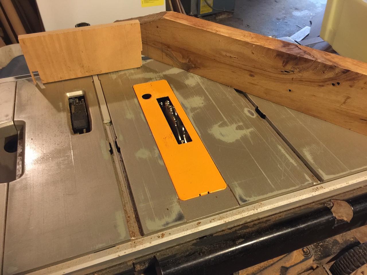
The second beam required a different method of support. I used more old oak and set up the table saw with the dado set, and made some supports. Some of this work is shown in the following three photos.
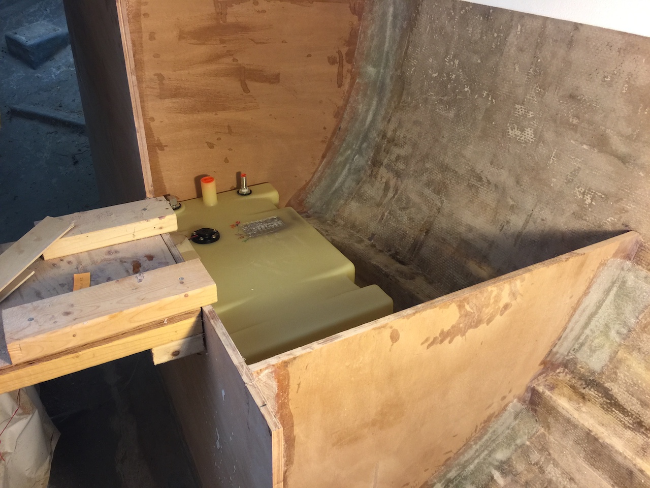
The following photo shows the fuel tank sitting on the beams. Eventually, there will be a plywood base the is screwed to the beams, and side supports, but that work will begin next week.
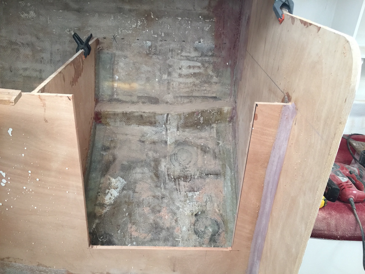
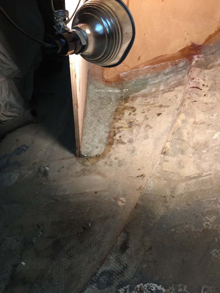
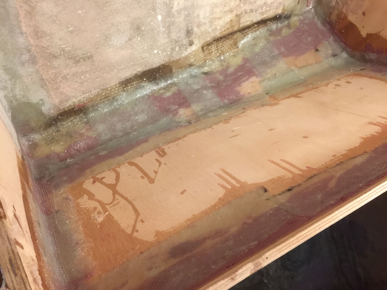
Meanwhile, I filled the acute angles where hull meets bulkhead with a foam/epoxy mix and glassed over it all. This has been my protocol everywhere in the boat, and will prevent water/dirt accumulation in impossible-to-reach areas.
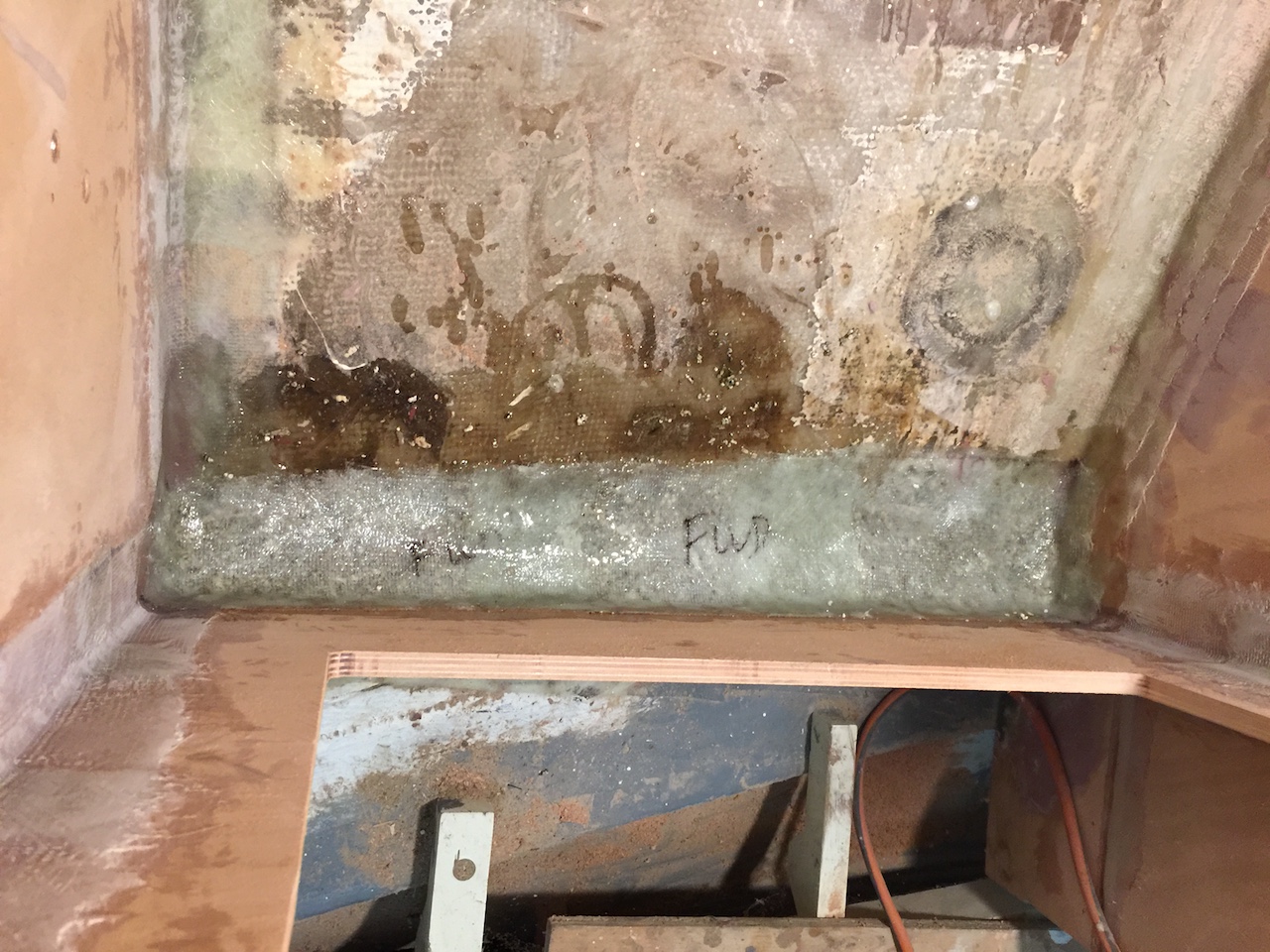
While I was at it, I filled in the acute angles on the under-cockpit side of the galley, too.
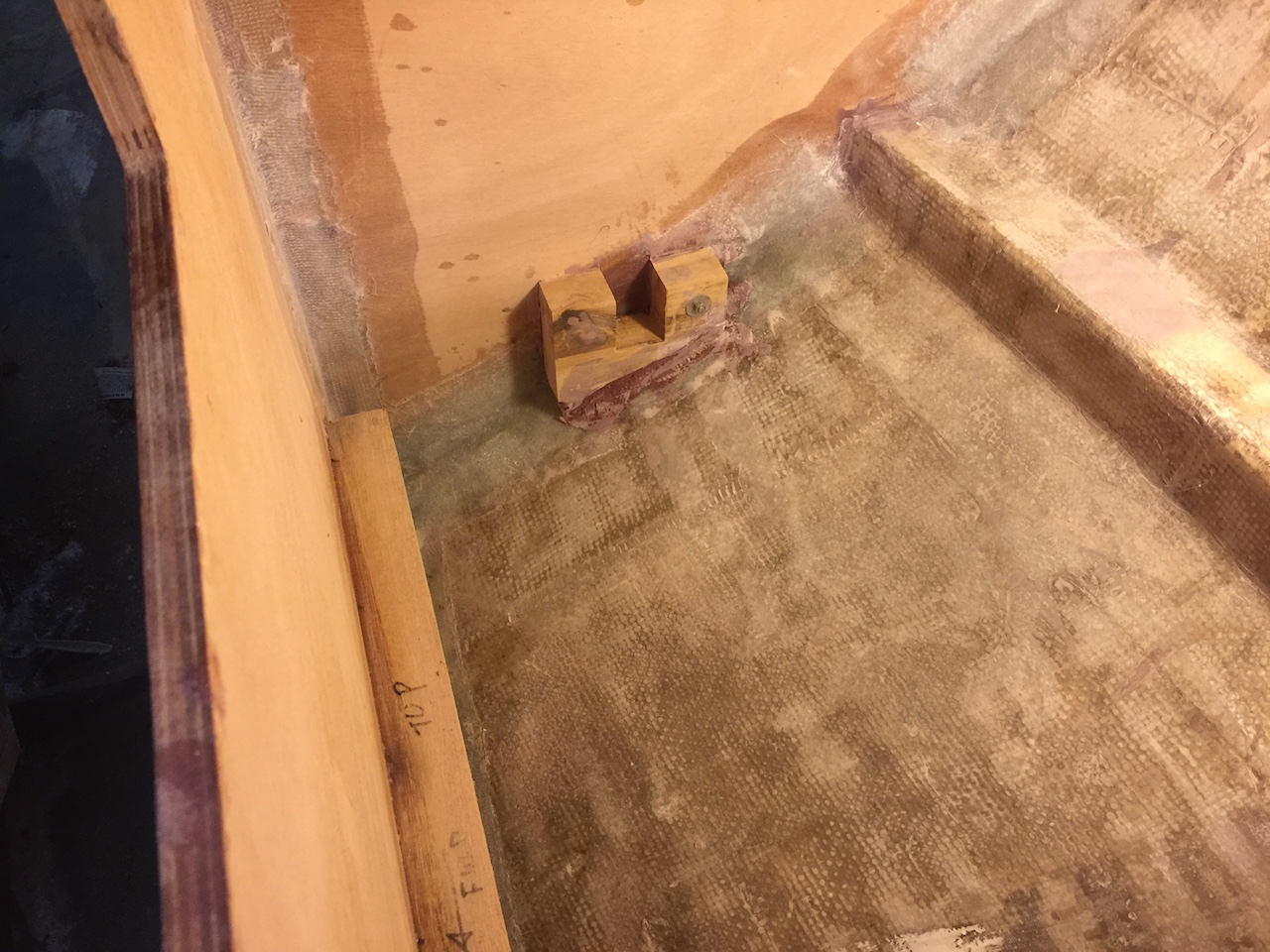
The stove weighs about 70 pounds, so a strong structure must support it. I glued up some plywood to make thick blocks.
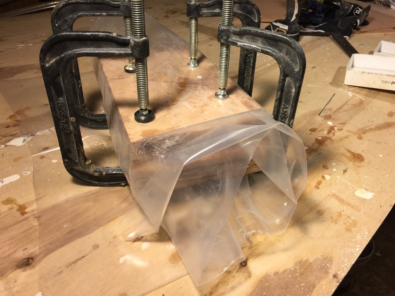
After the epoxy dried I trimmed the blocks. The following photo shows a dry fit of the two blocks and a piece of plywood that defines the outboard edge of the stove compartment.
Next, I glassed/epoxied everything together.
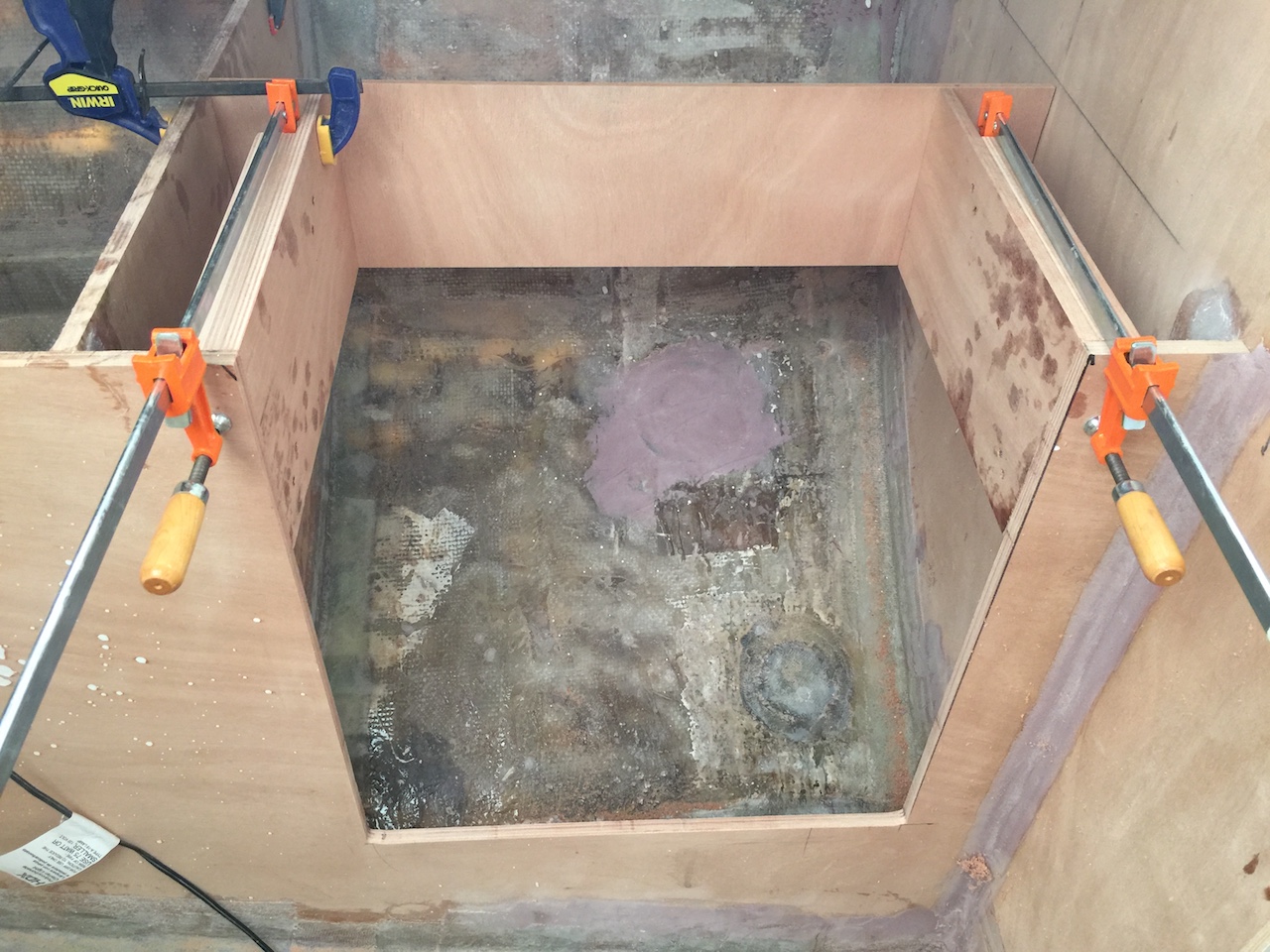
There will be two storage compartments under the counter space on the port side–one outboard of the oven, and the other outboard of the fuel tank. The following photos shows the installation of the inboard side of the storage compartment that will be outboard of the fuel tank.
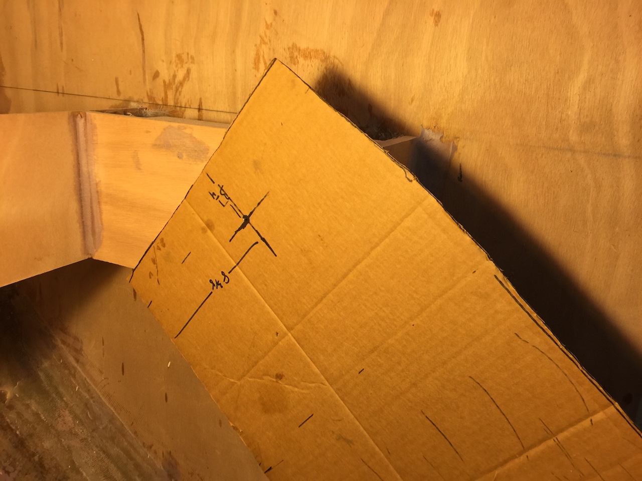
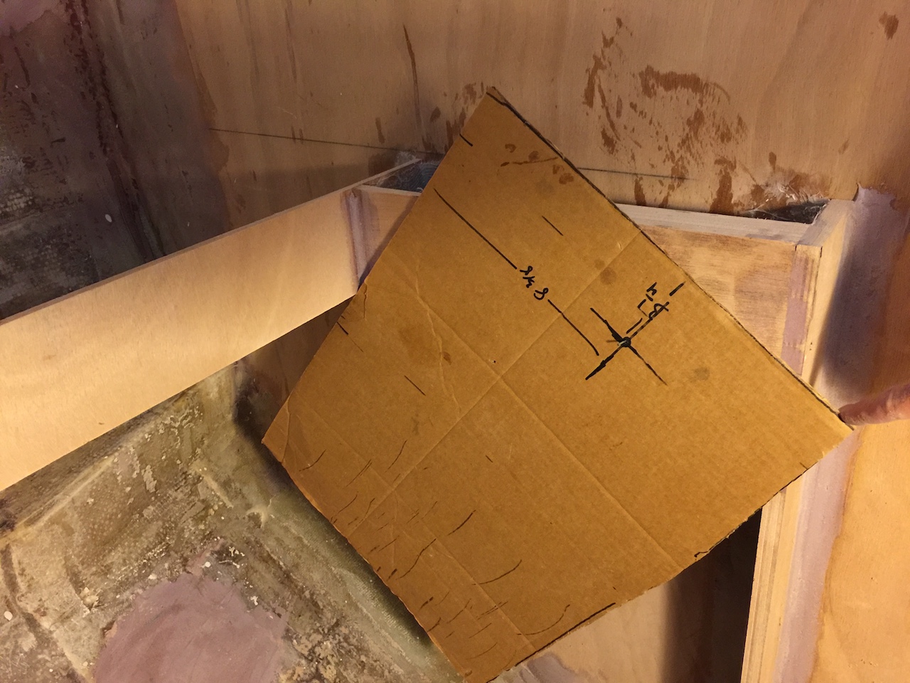
Meanwhile, I determined the approximate location of the gimbal mounts.
Using a cardboard cutout of the stove profile and a brad nail at the location of the center of the gimbal mount, I was able to determine that the stove will be free to gimbal at any angle of heel on port tack…
…but only to about 20 degrees of heel on starboard tack. While 20 degrees is a decent angle of heel, I wanted to allow for about 40 degrees.
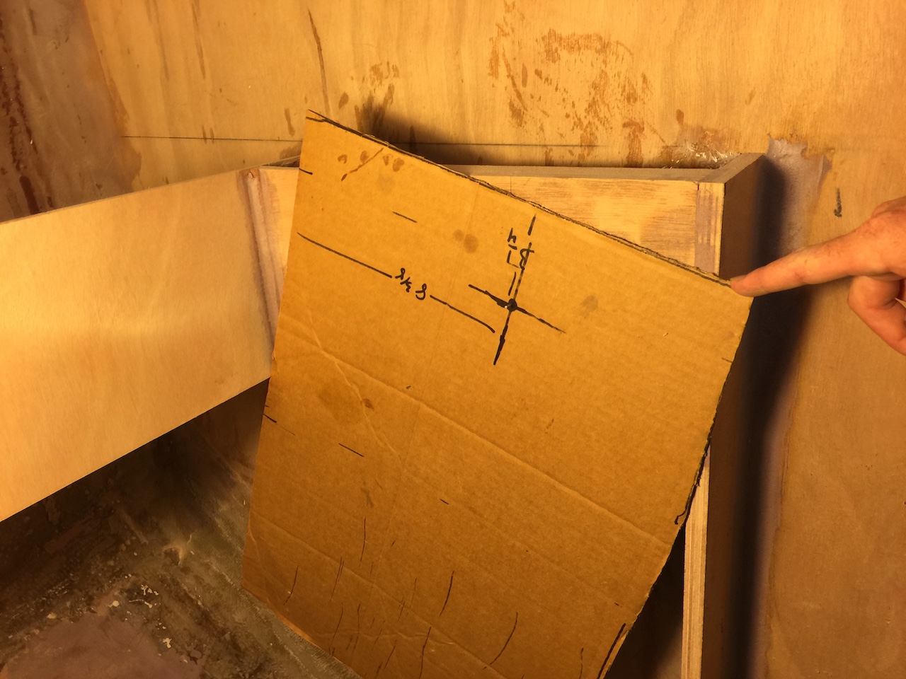
I cut the outboard side of the support by about 3 inches, and moved the brad nail inboard by about one inch, which provided sufficient clearance for 40 degrees of heel.
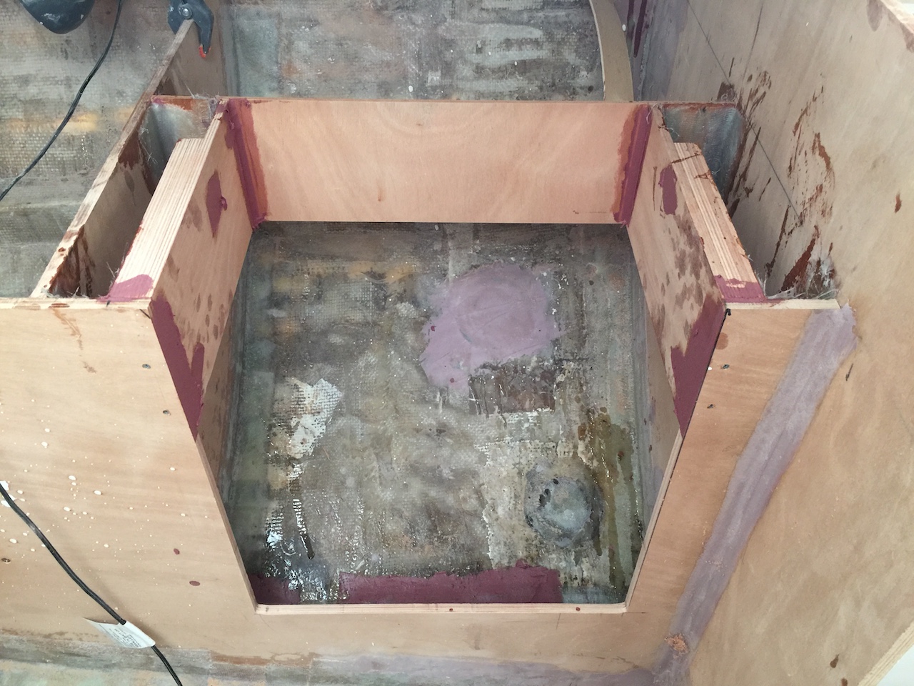
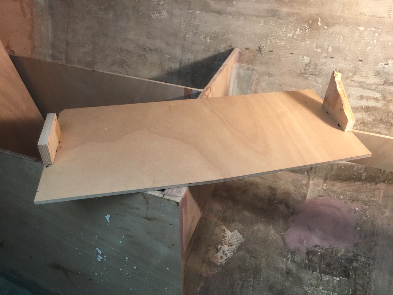
I installed the bottom of the aft storage compartment (not shown), but the storage outboard of the stove was more complicated because the lower-outboard side had to be angled to allow for the gimbaling stove. Holding pieces in place for epoxy and glass is sometimes a challenge, as it was here. I used hot glue to attach some temporary pieces to the plywood, then flipped it over and screwed the temporary pieces to the bulkheads just fore and aft.
I made the bottom of this storage locker in two pieces, and glassed it all together.
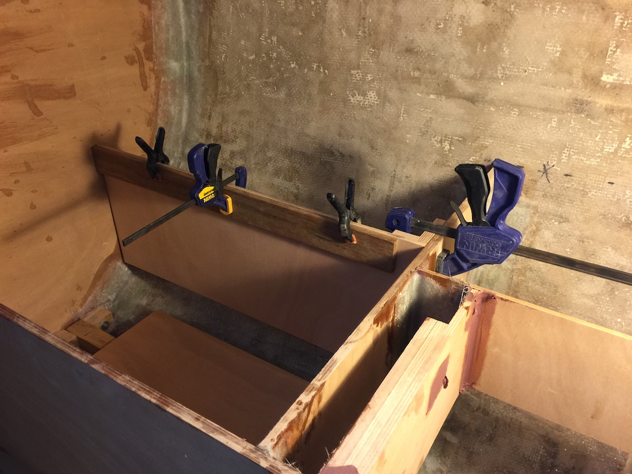
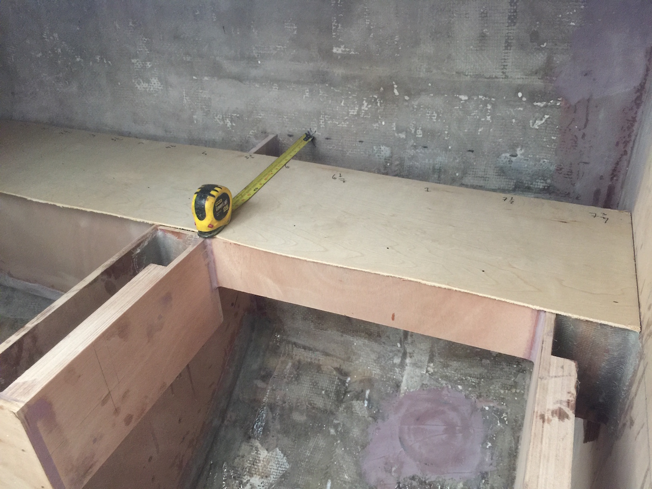
The countertop here will be have two lids to access the top-loading storage and fuel tank. Above the counter there will be cabinet storage with sliding doors. The permanent (non-removable) pars of the counter will be made in four pieces (more details to come) and the first will be the one that runs along the curved hull. the photos below show a piece of scrap plywood that I made into a template.
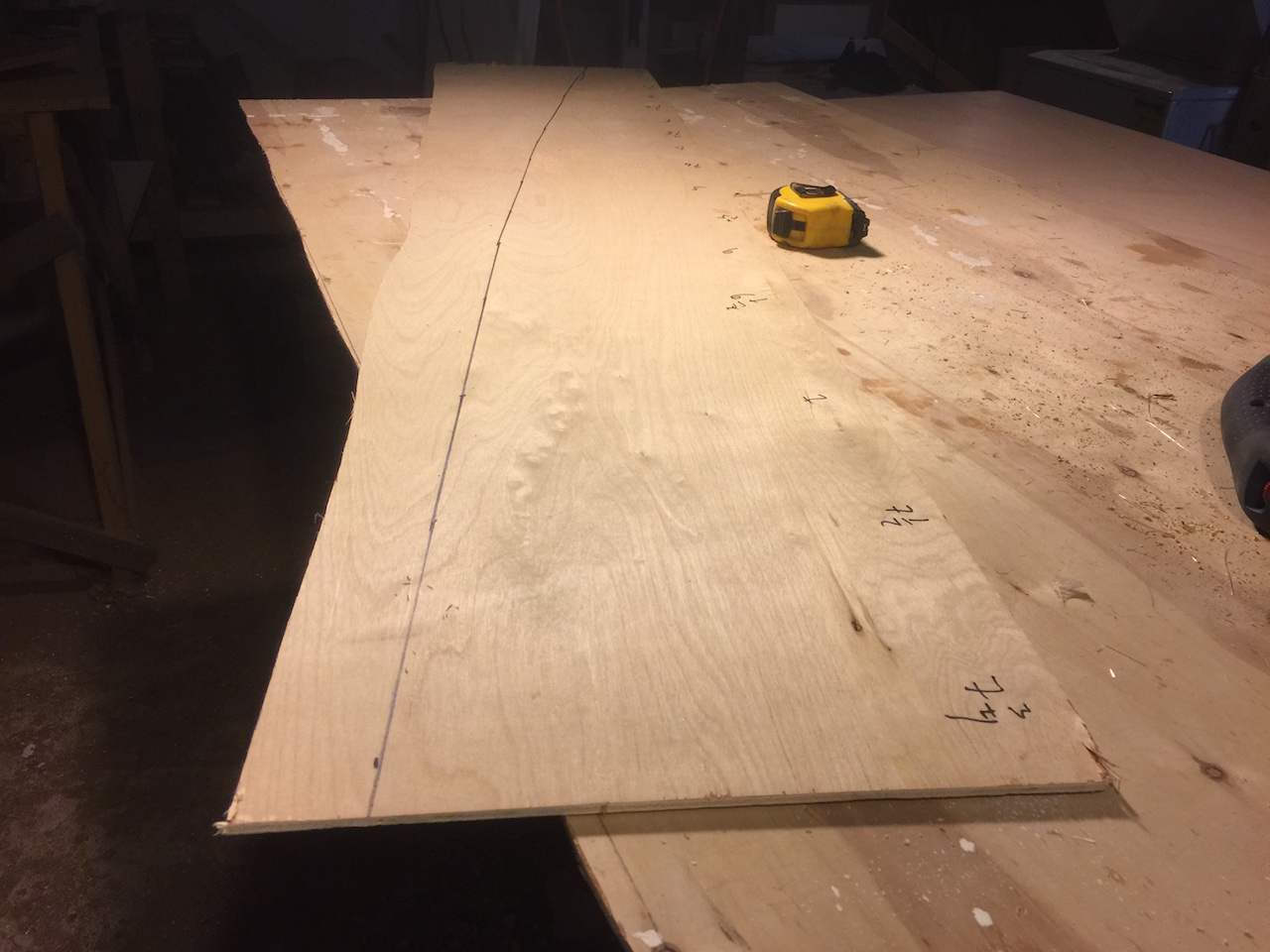
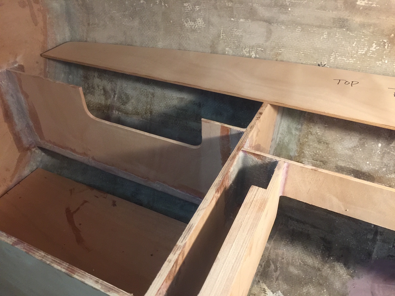
Using the template, I cut the piece out of 3/8 inch marine plywood. Before test fitting, I realized that the this piece would restrict access to the storage outboard off the fuel tank, so I used an old window template to improve the situation, as shown in the following two photos.
Next, I painted the inside of these storage areas with a first coat of primer.
The next steps will be to finish the support structure for the fuel tank and then continue with painting and installing the countertops.