4/21/14: Tanks
This photo was taken looking aft. You can see the two water tanks. The tanks are connected with a hose, so they are effectively one tank with a total capacity of about 110 gallons. It is not clear, at this point, whether tanks will be refurbished and reused or replaced. Access to the tanks requires removing some of the floor beams and one compression post.
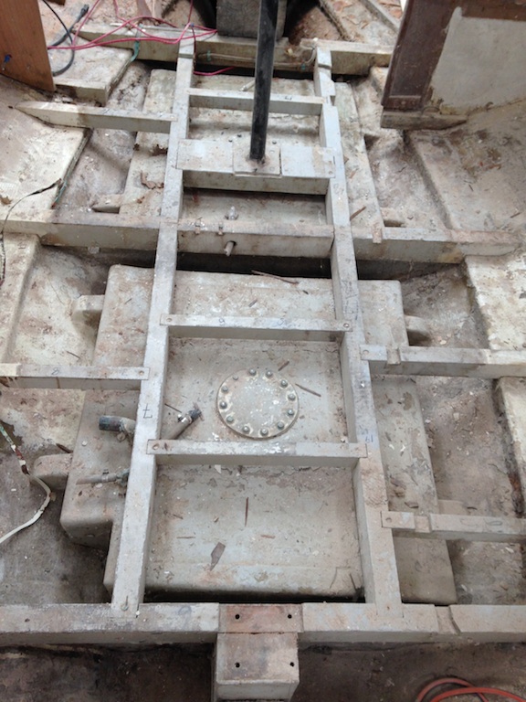
The water tanks.
First, however, the water is siphoned out to remove weight and minimize spillage as the tanks are moved out of the boat.
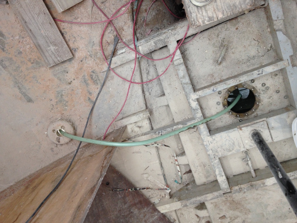
Siphoning the water from the aft tank.
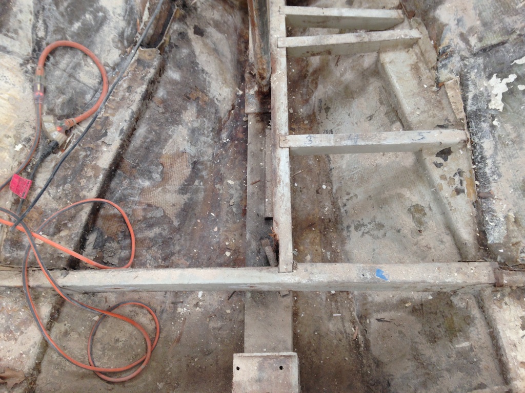
Removing the floor frames provides full access to the tanks.
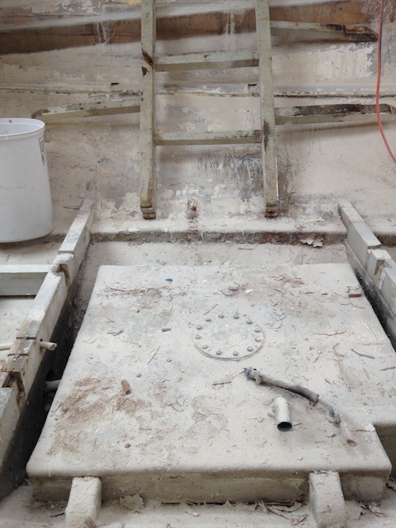
The forward tank with the covering floorboards removed.
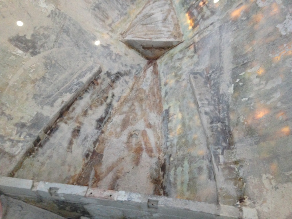
Here is the space under the forward tank, which has not been seen by human eyes for 44 years. This keel is deep and Thalassa has internal ballast–that is, instead of a single piece of lead bolted through the bottom of the keel, Thalassa’s keel fully encapsulates the ballast. In this case, lead is placed into the keel and then surrounded by concrete (or something like that). Under the debris in the photo is the top of the concrete slab, which was created in six downward “steps” from fore to aft. The concrete was originally protected from moisture by a layer of fiberglass. In time, however, this layer has deteriorated and in some cases has failed completely.
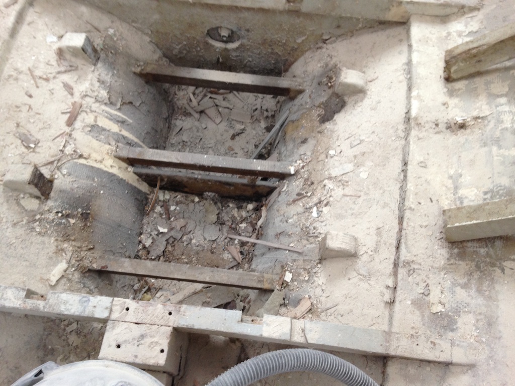
The space under the forward tank.
The aft tank is the larger of the two and removing it was difficult.
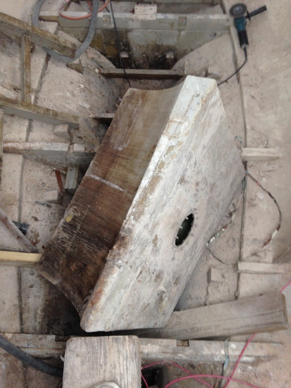
The aft tank.
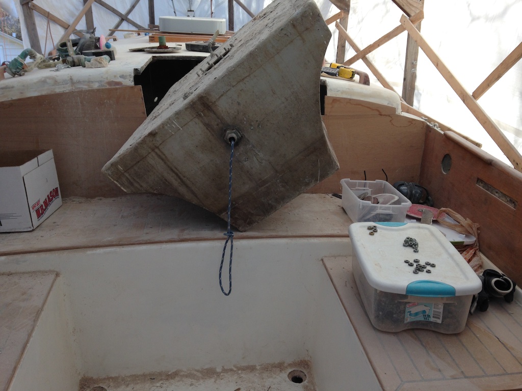
The aft tank coming out of the companionway.
Below we are looking down into the space under the aft tank (after removing debris). You can see where the fiberglass “protection” has failed completely. These layers must have been laid up improperly, as fiberglass should not develop cracks like this. These layers are brittle and can be broken up with bare hands.
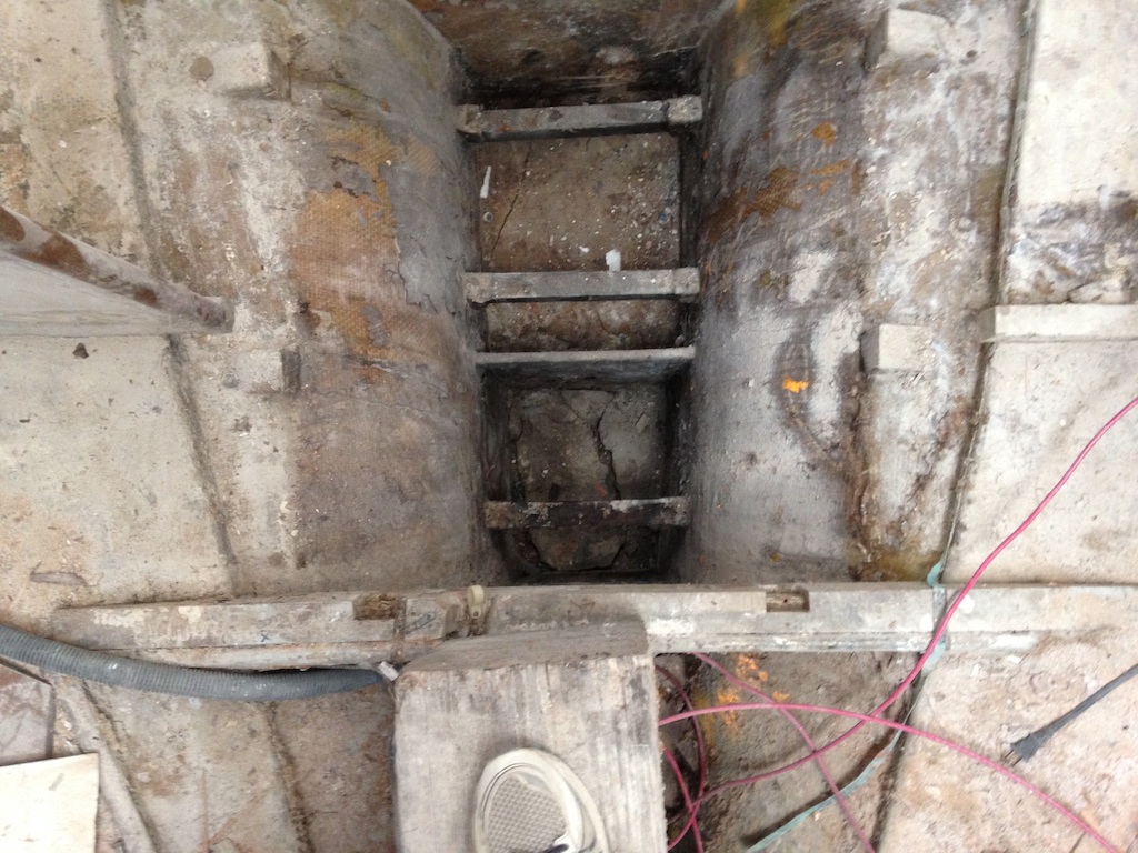
The space under the aft tank.
Here is the space forward of the tanks, which is under the head and forward cabin. The forward compression post sits on a long, heavy block of wood.
The space under the head and forward cabin.
The bottom of the forward compression post is rusted. All three compression posts will be replaced with heavier gauge stainless steel posts.
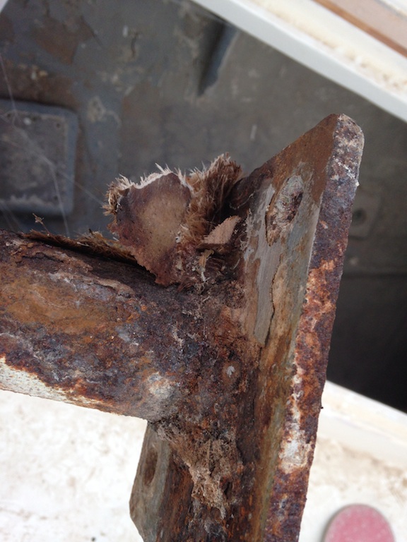
The bottom of the foreword compression post.
The long, heavy block distributes the force from the compression posts. Here it has been removed and the bottom of the block is wet and shows signs of rot. It will be replaced by a laminated beam of white oak.

The bottom of the big block is wet.
Here the top two steps of concrete have been cleaned up. Each step is separated from the next with a partial bulkhead. Here I have removed the small bulkhead between the top two steps. The next job on the list is replacing this bulkhead, then glassing the top step.
The top two “steps” of concrete.
The question of tanks has not yet been answered, but integral tanks are on the list of possibilities:
“Integral tanks and their baffles provide structural strength to the hull,” he continues “Non-integral task provide the opposite, by creating a void where structure cannot be.”