5/25/14: Engine Bed and Bilge
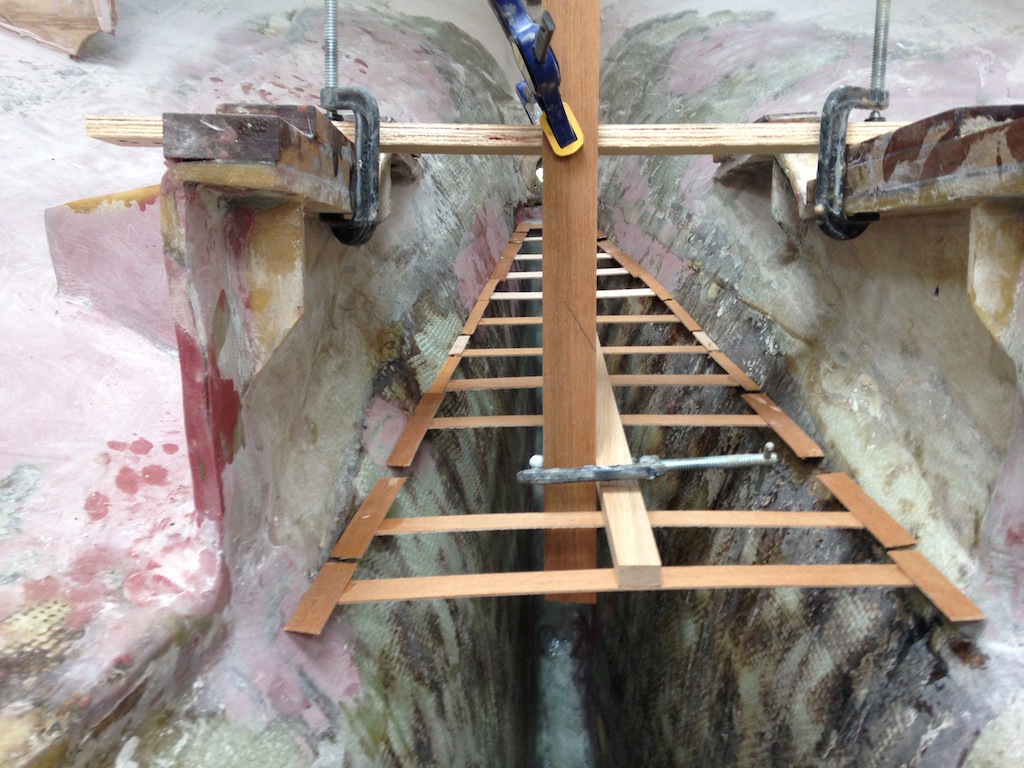
Removing the bulkheads that flank the engine compartment made getting into and out of the cabin a challenge. A simple ladder was constructed, using two pieces of two-by-four and some scraps from the old interior
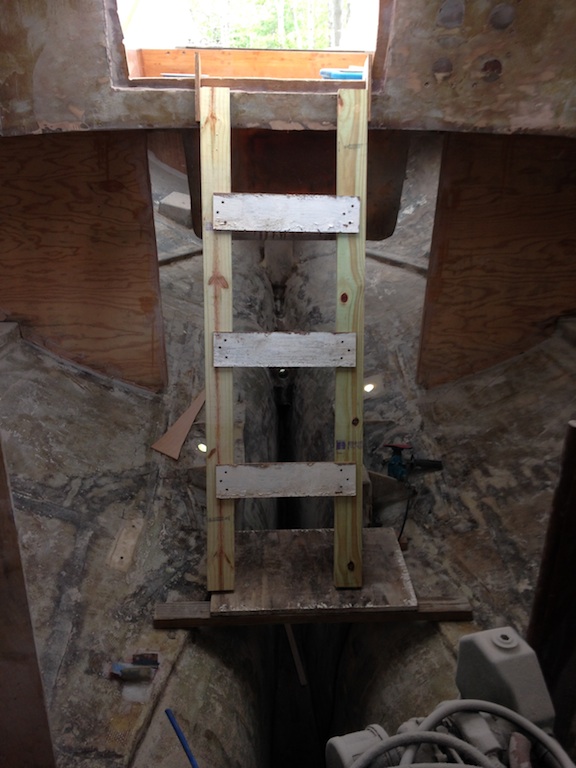
A 10-minute ladder
The following photo shows the hull just starboard of the engine support. This hole was the old raw water intake and we can see where the original bulkhead was tabbed. Lots of dirt had accumulated in the spaces in and around the engine support. The goal is to clean this up and smooth out the uneven texture.
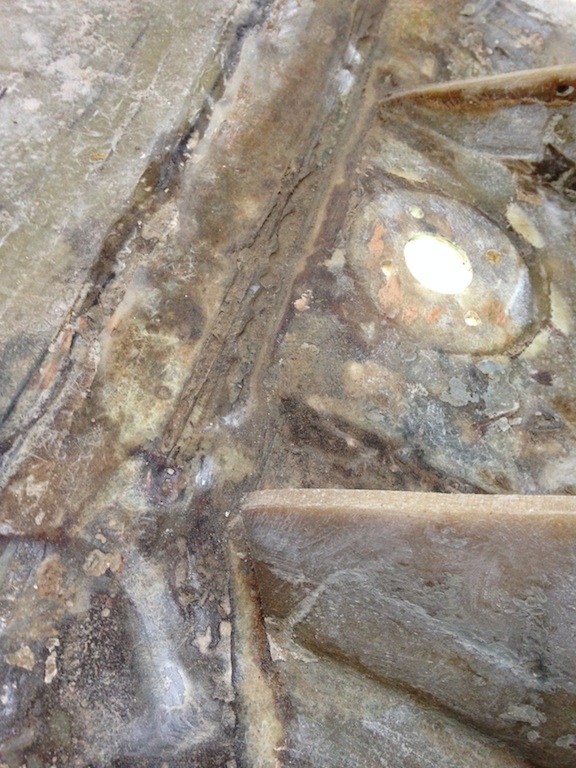
Dirt and unevenness
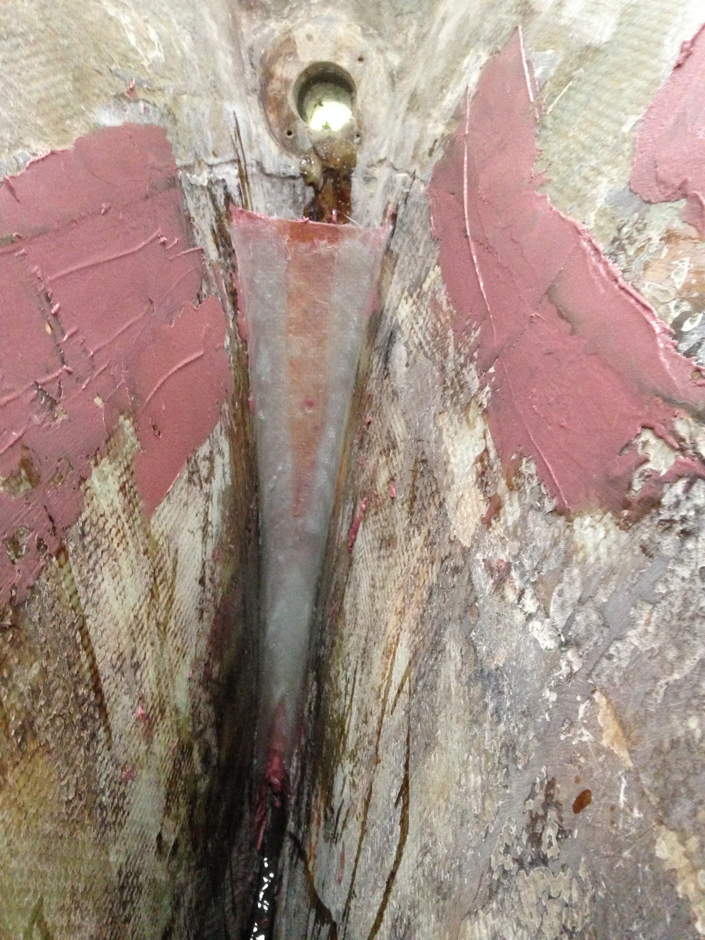
After a thorough cleaning, thickened epoxy was applied (the pink areas in the photo below). Scraps of heavy biaxial fiberglass cloth were used as additional tabbing for the engine support, as shown. This was the first of several iterations of filling and fairing in this area. Notice that the forward end of the engine support is irregular with some circular machined holes. This situation will be addressed later in this post.
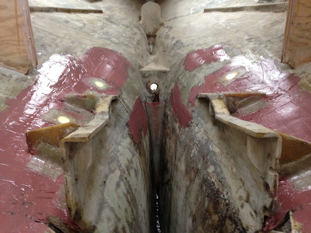
Thickened epoxy and biaxial fiberglass cloth
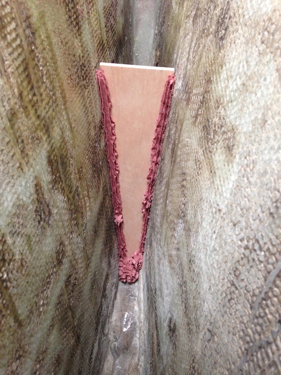
The following photo shows a new mini bulkhead that separates the inaccessible space under the stern tube from the rest of the boat. This space (which cannot be seen in the photo) will be filled with small scraps of wood (teak, plywood, and oak–whatever scraps are handy). Next, unthickened epoxy will be poured over the wood, filling the spaces between the wood. Heat is generated when epoxy cures, so care must be taken to fill this space gradually, on cool days, and using only slow hardener.
The mini bulkhead
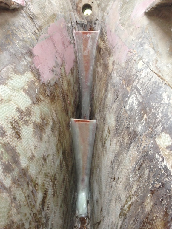
There will be three of these mini bulkheads in the bilge. The following photo shows the second. A pastry bag was used to create the decorative bead of thickened epoxy that will be turned into a fillet with the back of a plastic spoon. Throwaway pastry bags and nozzles can be found at most supermarkets or department stores.
The second mini bulkhead
The first and second mini bulkheads
The next photo shows the Fein Multimaster, which is set up here for detail sanding. It is used daily in the bilge areas, particularly to get into the sharp corners of the engine support.
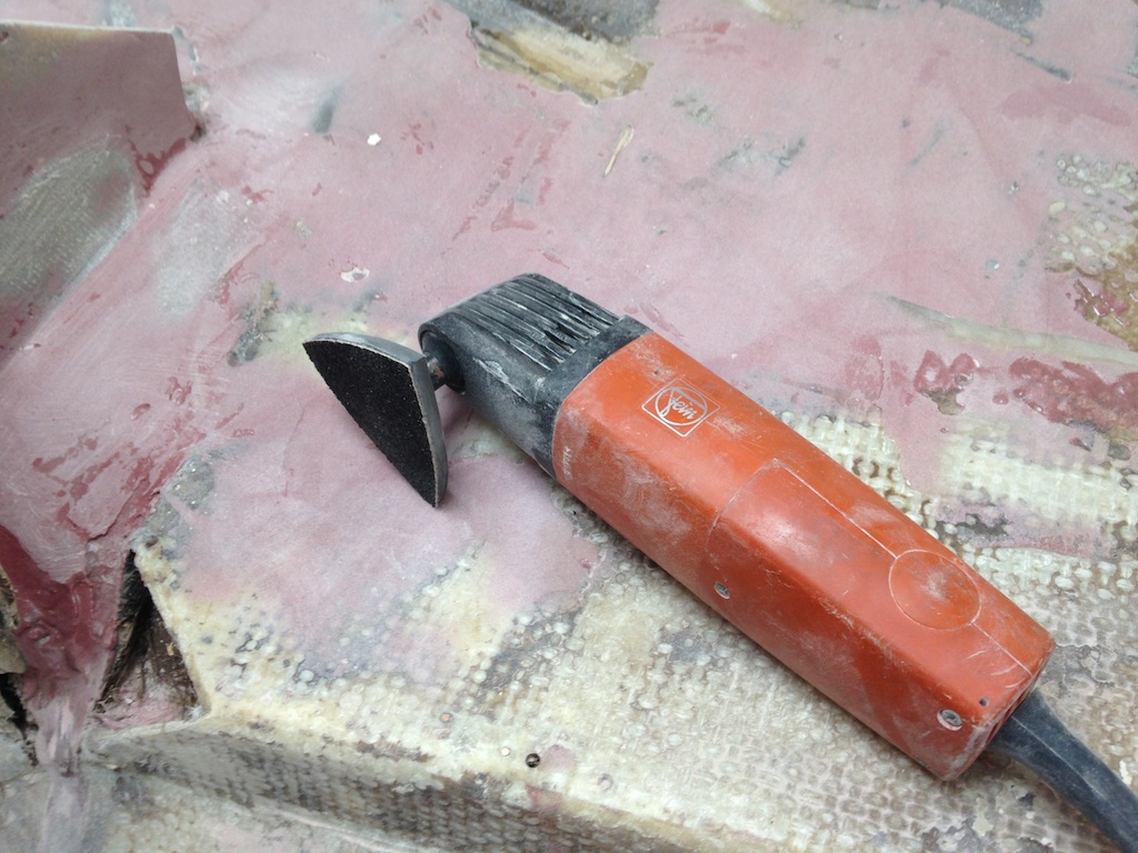
The Fein Multimaster tool
The photo below shows part of the engine support after several iterations of filling and sanding. The result is a smooth surface with no sharp edges, which facilitates painting and cleaning.
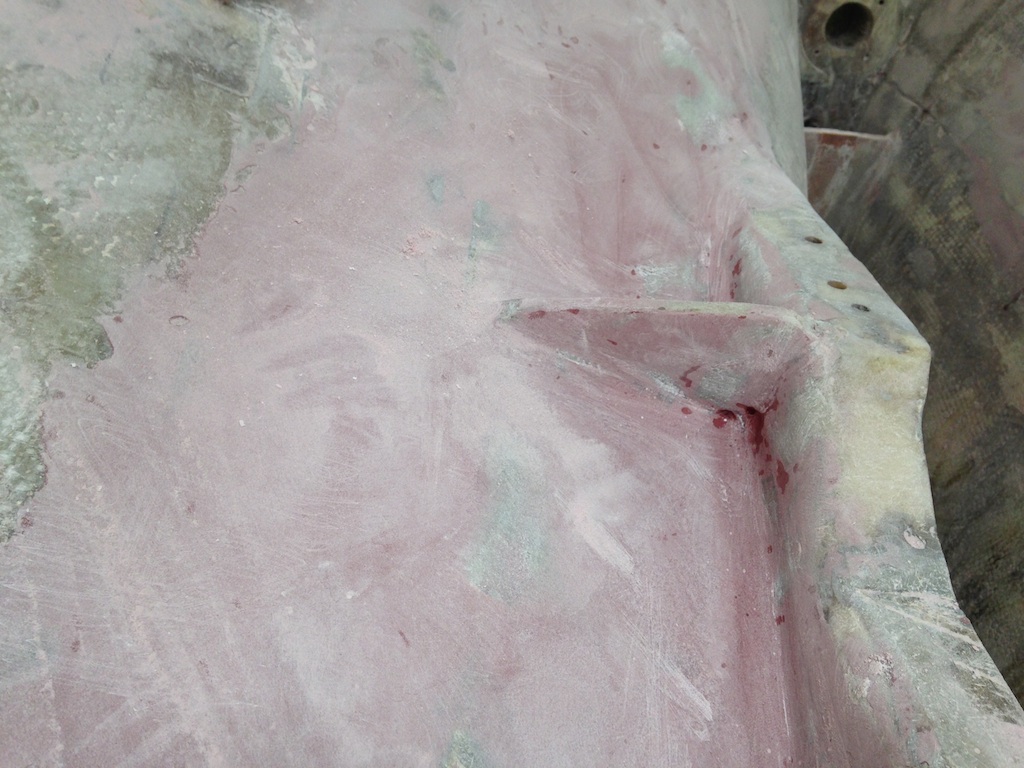
A smoother situation
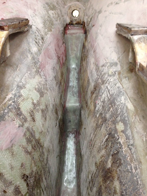
As we have seen, the front of the engine support is irregular and full of holes. Pieces of wood were clamped perpendicularly to create surfaces that define the forward end of the engine support. Strips of fiberglass were run vertically along the outside of the forward end of the engine support. These are hidden by the wood in the photo.
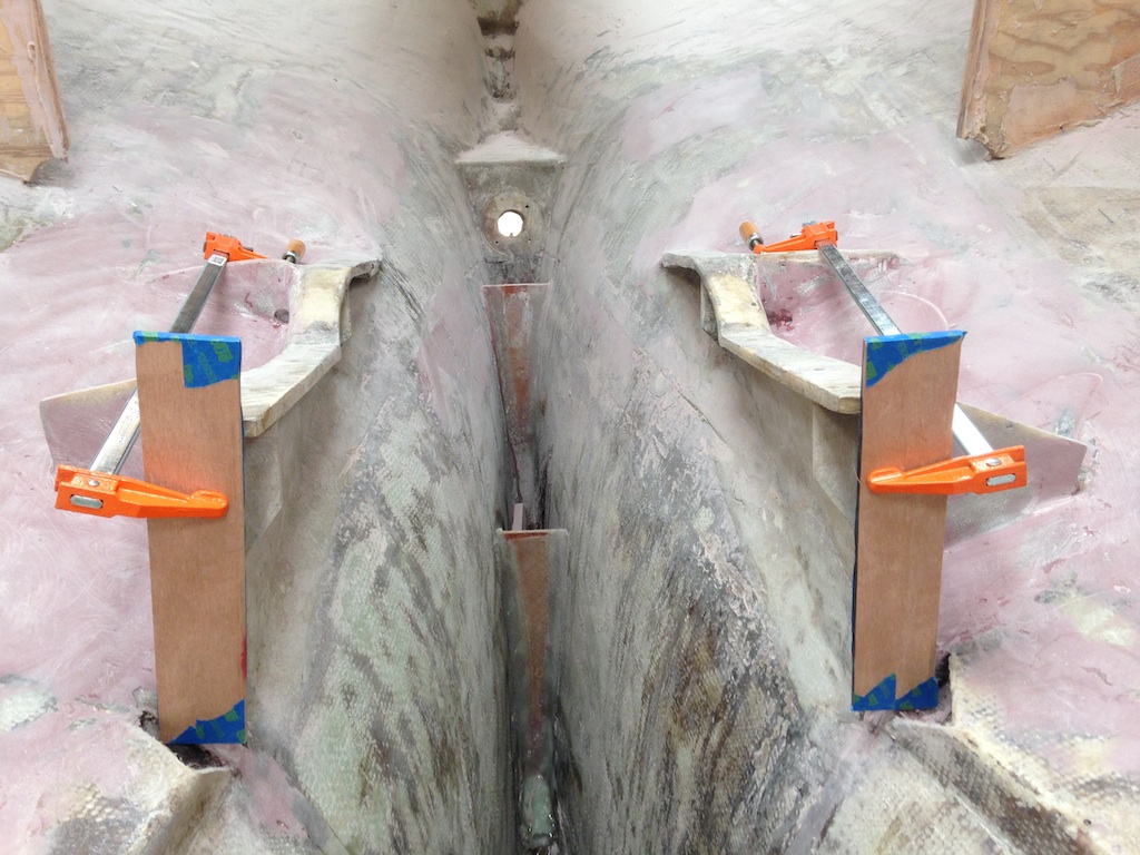
Preparing to clean up the front of the engine support
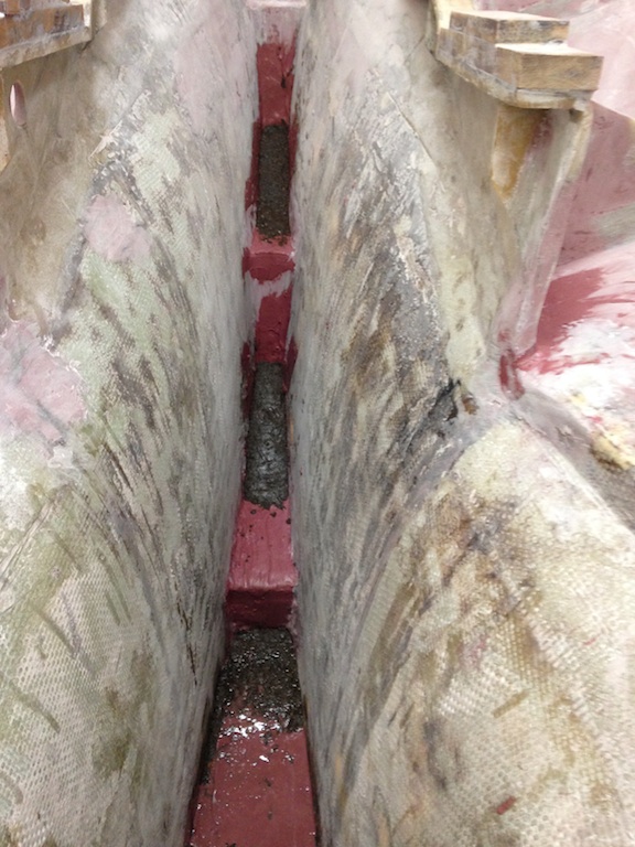
After the fiberglass strips were dry, the wood was removed, and now the fiberglass strips were built up with thickened epoxy, as shown in the photo below.
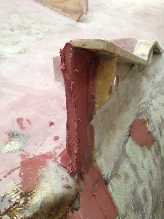
Ready for sanding
The motor mounts are not attached directly to the engine support. Blocks of wood are attached to the engine support, and then bolts are used to attach the motor mounts. New wood blocks were fabricated from teak recycled from the old interior. The old blocks were used as templates.
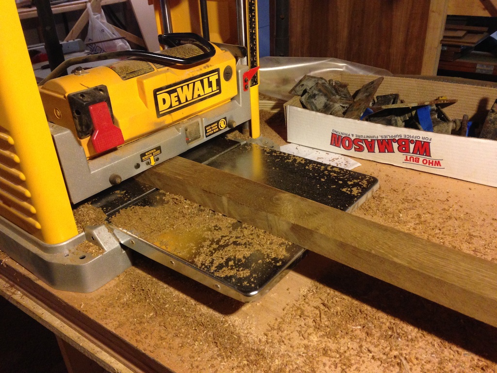
Using the thickness planer to create the desired thickness
Fabricating wood blocks that support the motor mounts
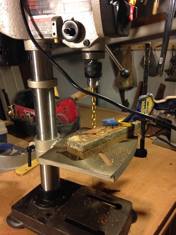
Next, the blocks of wood and motor mounts were test fitted, as shown below. (You can also see in this photo that the mini bulkheads are in place, the empty spaces have been filled, and work has begun on smoothing out these areas in preparation for glassing and eventually painting.
Testing the alignment of the holes
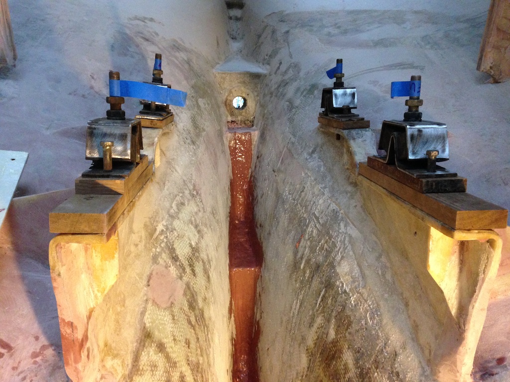
After test fitting, the blocks were bedded in thickened epoxy and clamped into place. The old bolts were used to maintain proper alignment during this process.
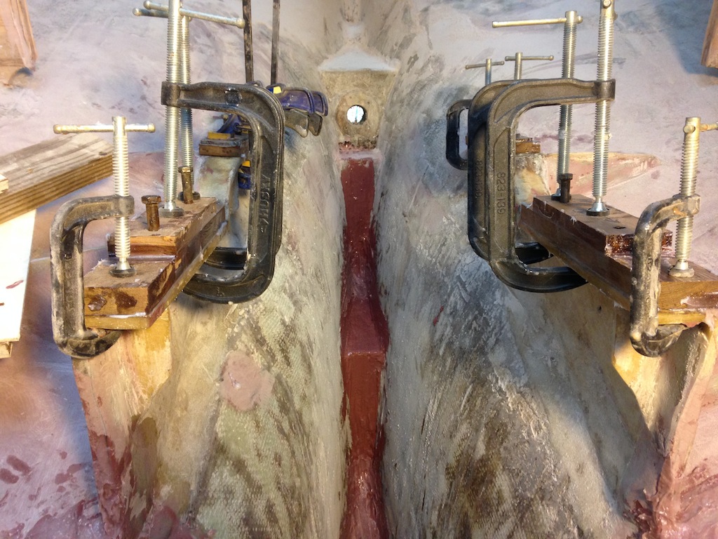
The new blocks
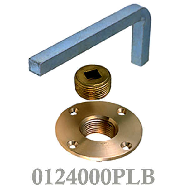
Recall that some deteriorated concrete was removed from the bilge. One of the resulting problems is that the level of the bilge no longer matched the level of the garboard drain plug. Custom-fitted plywood and oak was used to fill the space, as shown in the photo below.
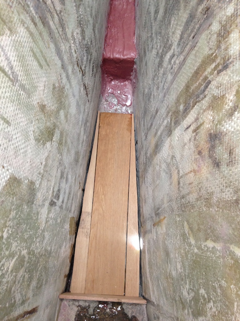
Raising the level of the bilge
These pieces of wood were coated with epoxy and then more epoxy was drizzled into the gaps. Gap filling continued with a mix of epoxy and store-bought sand. This combination produced a heavy, dark paste that was used as shown in the following photo. A small amount of epoxy produces a surprisingly large volume of this paste.
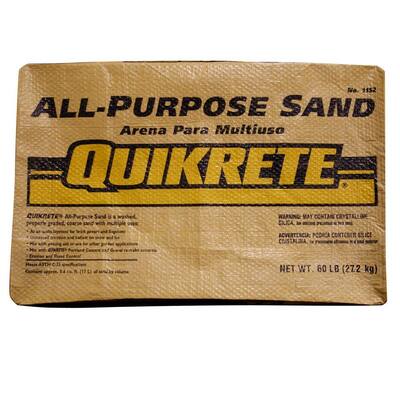
The dark areas are the epoxy/sand mixture.
Next, these new “steps” in the bilge were glassed over with several layers of biaxial cloth.
Glass
The bilge area was then scrubbed with soap and water in preparation for sanding. A pattern for the new drip pan was constructed while waiting for the area to dry out.
The pattern for the new drip pan
Eventually, the area was sanded and a coat of white primer was applied. The results are shown in the following two photos.
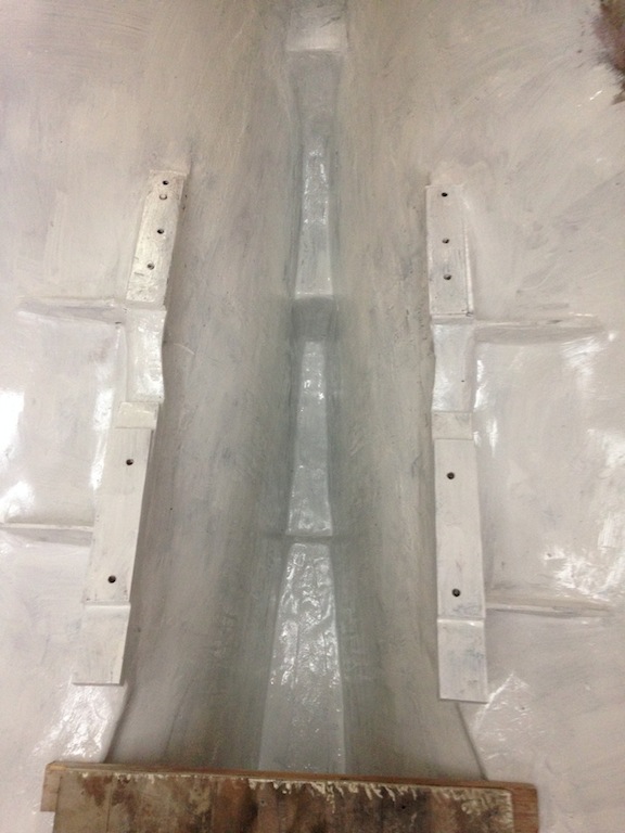
The bilge area, from above
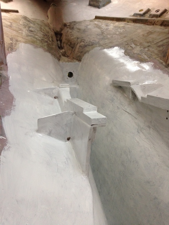
The bilge area, with primer