8/17/14: Floor Beams
The tanks require more plumbing (inlet and outlet tubes), but this plumbing will be done later. The next task is to build floor beams on which a temporary floor will be built. You may recall that a few athwartship beams had been constructed. (Click here to see a previous posts that shows this work.) After the tanks were built, however, it was found that the location of these beams was not ideal, so new floor beams will be constructed from scratch. (The new floor beams will be about 1/2″ lower, which will provide an additional 1/2″ of headroom.)
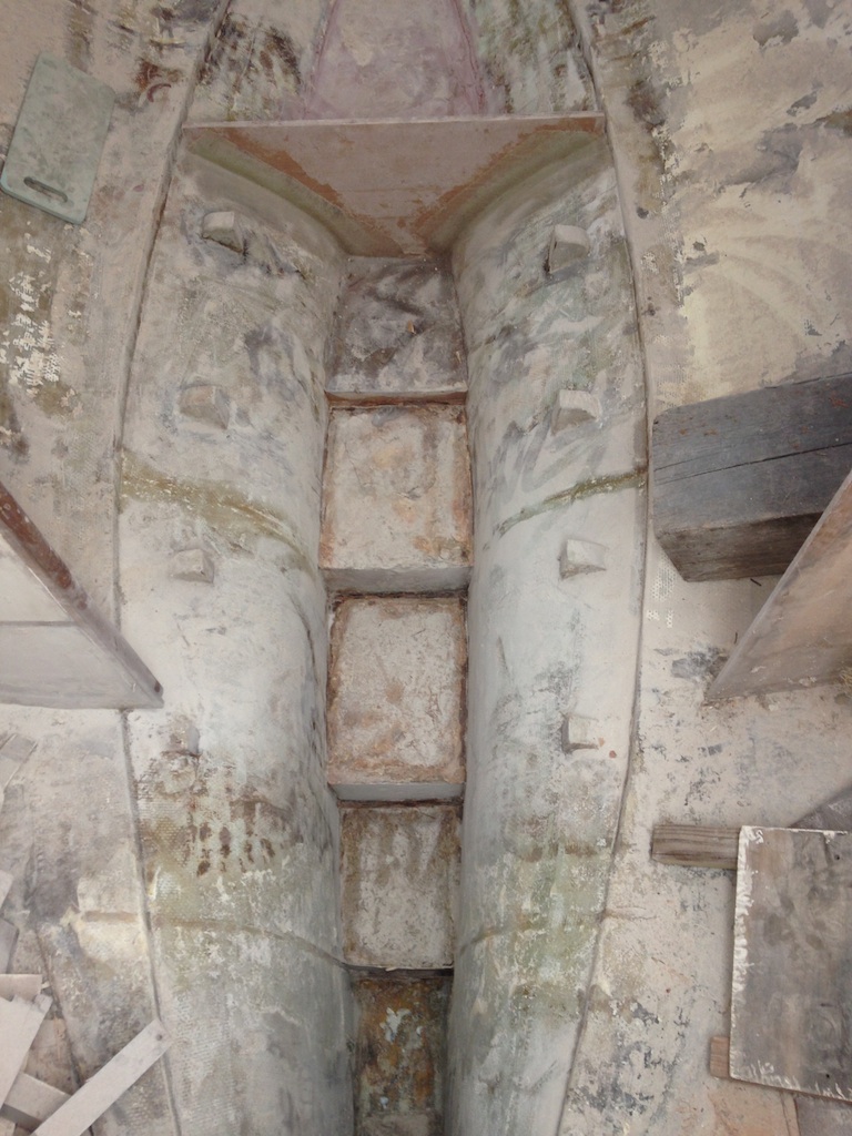
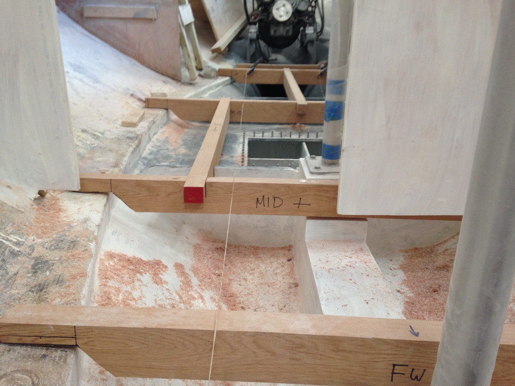
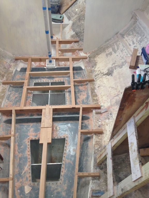
The following photo was taken looking forward and shows the beginnings of the beam structure in the area over the forward tank. Slots will be cut into the top of the forward tank bulkhead accommodate the fore/aft beams, which here sit on top of the bulkhead.
Slots must be cut in the forward tank bulkhead to make way for the fore/aft beams seen here.
The router with a straight bit was used to cut these slots. On the left in the photo below shows part of a rough jig that was used to guide the router.
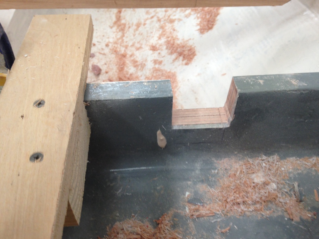
A slot in the top of the forward tank bulkhead
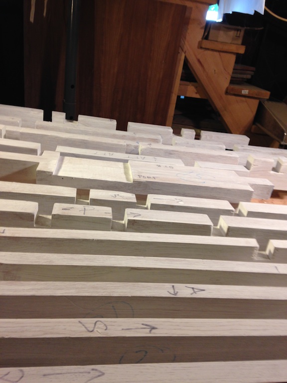
The dado set was used to cut slots in the beams.
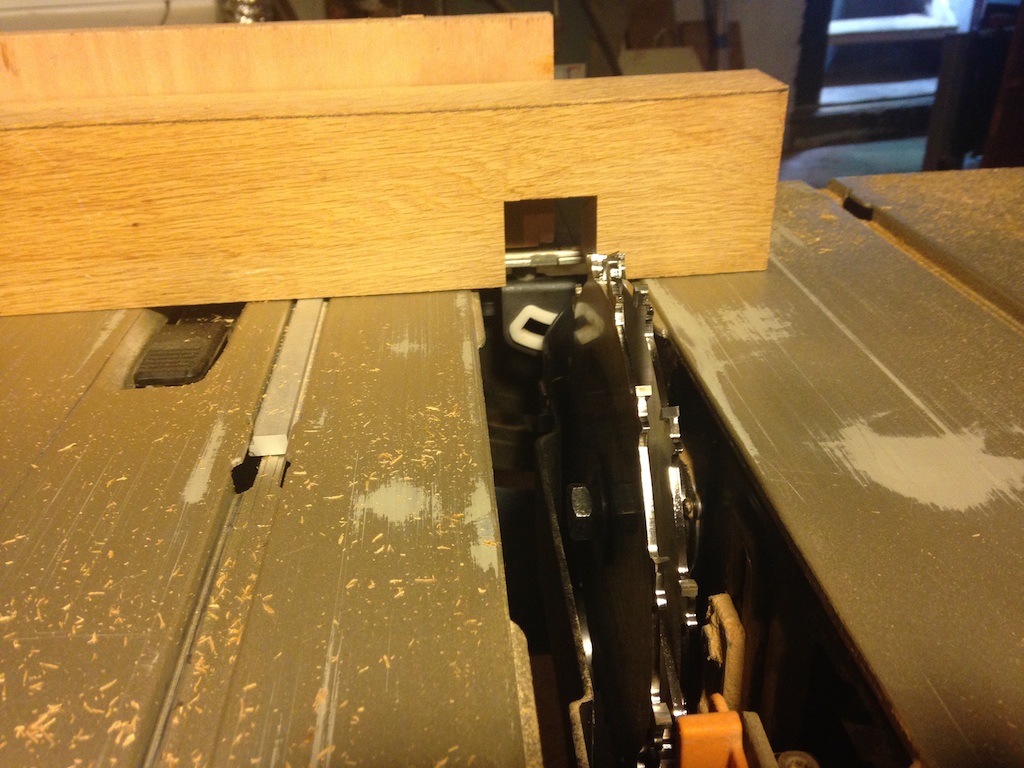
Using the dado set to cut slots in the beams
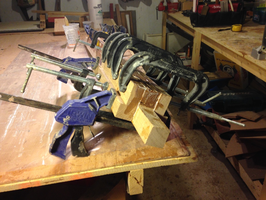
As an aside, much of the lumber (white oak) that was used for the floor beams was purchased rough. Rough-cut lumber is typically not straight, so it won’t run cleanly across the table saw fence. A straight edge can be created, however, by clamping a straight piece of lumber across one side of the rough lumber and running the straight edge along the fence. The following photos show the results of this process.
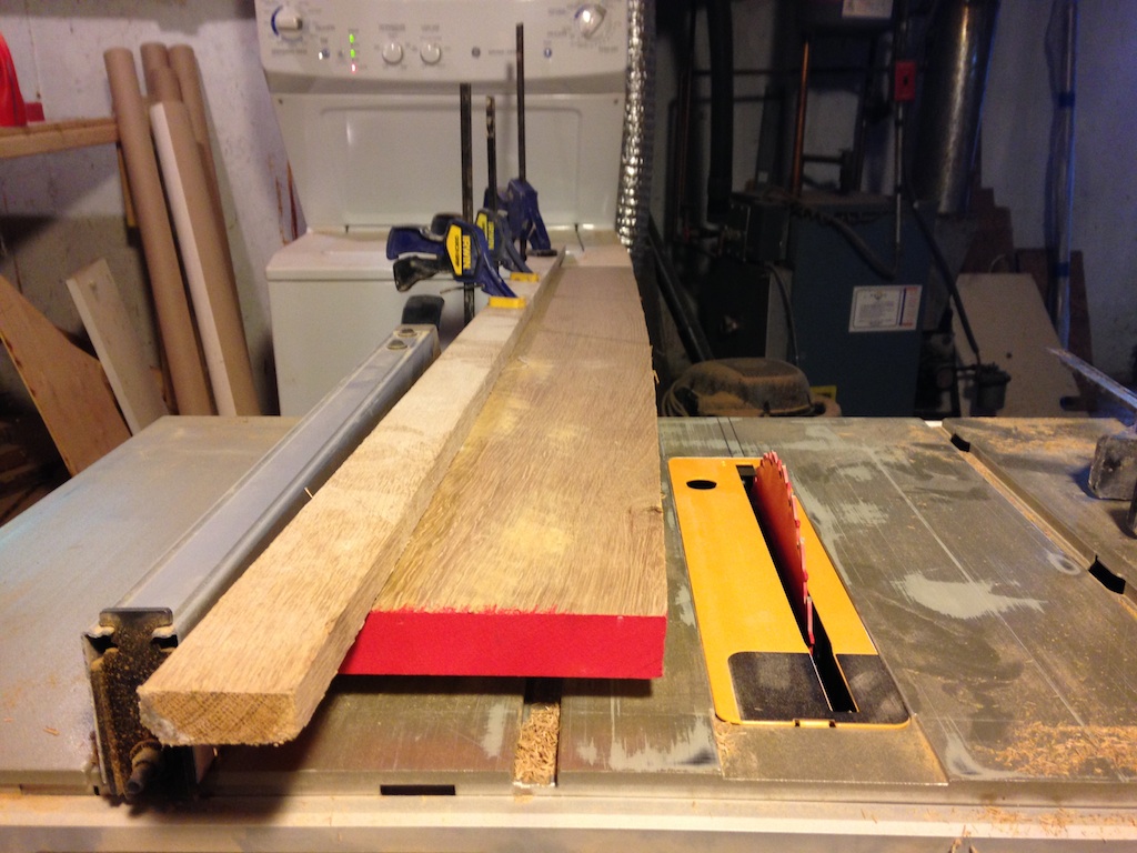
A simple jointing jig
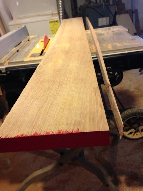
A straight edge and the leftover scrap
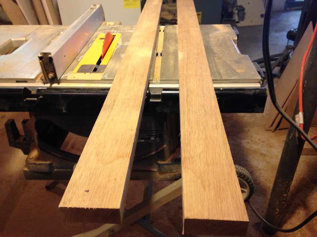
With a straight edge on one side, straight cuts can be made.
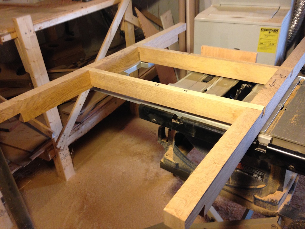
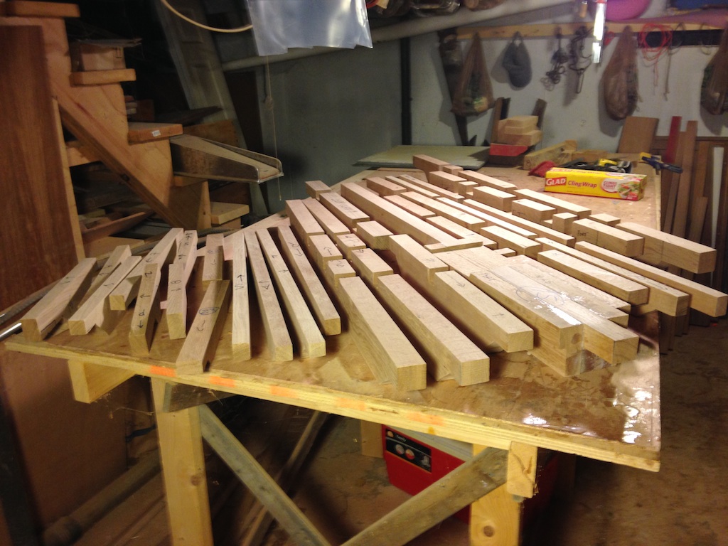
Test fitting some beams in the workshop
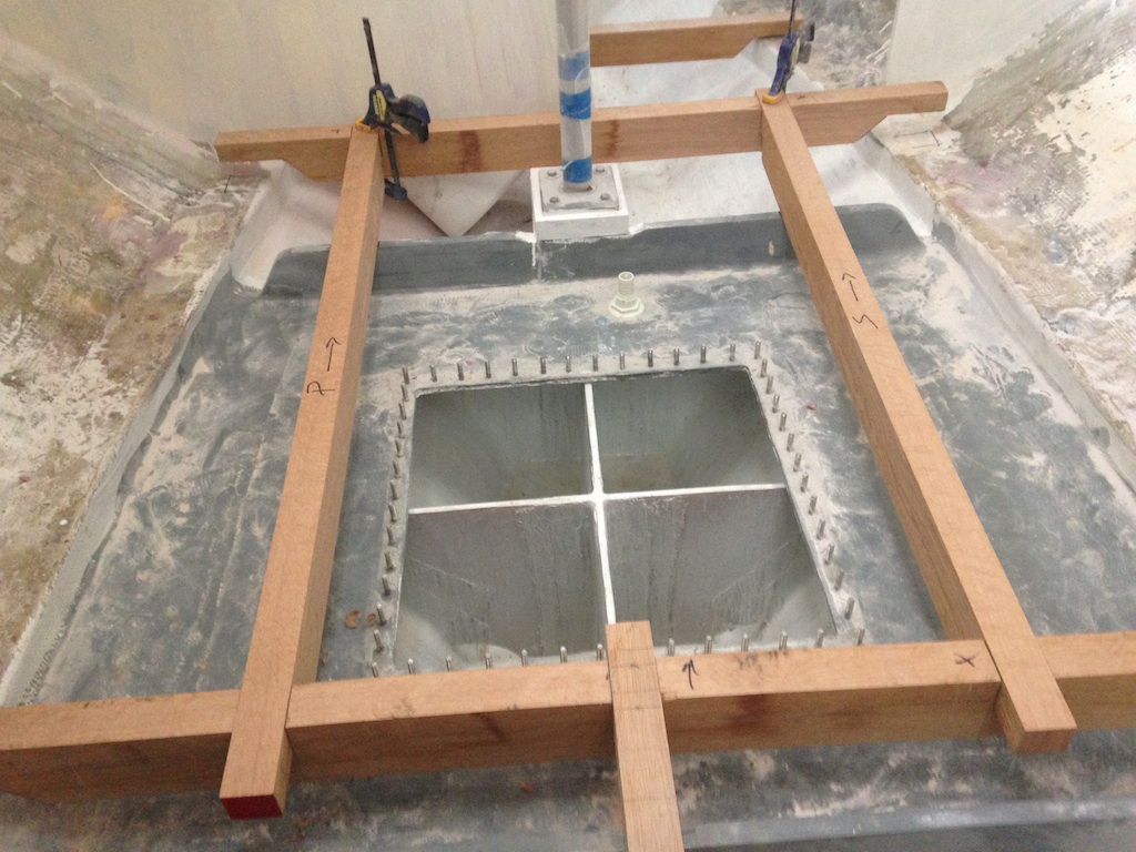
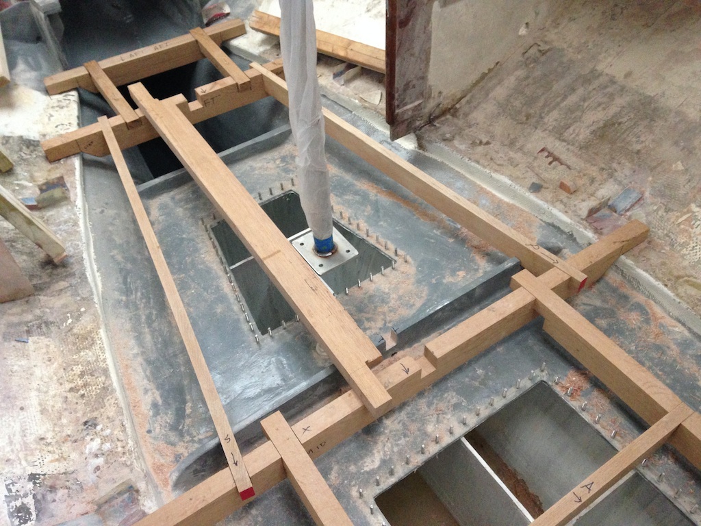
Careful measurements (using strings and levels) were made to ensure that the floor will be level.
Using a string to check that the floor will be level
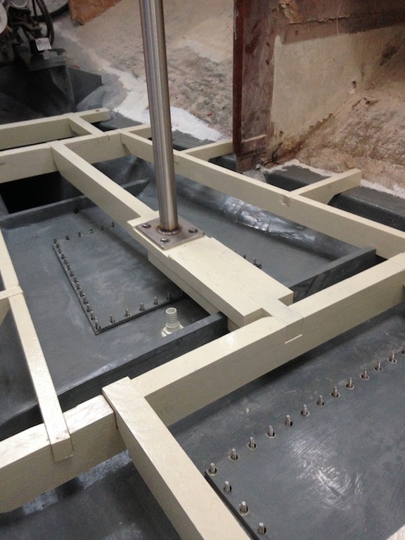
In the previous photo, the two compression posts support the forward and aft ends of the mast step. A third compression supports the coachroof just forward of the galley area. In the photo below, this third compression post is bolted to the coachroof and we can see the bottom plate hovering over the front of the aft tank. The floor beam that runs under this compression post must be installed before final installation of the post.
The third compression post, hovering above the aft tank
First, however, this supporting beam must be built up to be stronger, and wider to accommodate the plate at the bottom of the post.
Building up the beam that runs under the aft compression post
All three compression posts were installed under a small amount of compression, and in each case the coachroof was jacked up a little to facilitate this. In the photo below we can see that the thick, forward end of the beam fits snugly into a cutout in the bulkhead that separates the forward and aft tanks. In this way, the compression is transferred to the bulkhead (which is extremely strong) and not the athwartship floor beam just forward of this bulkhead.
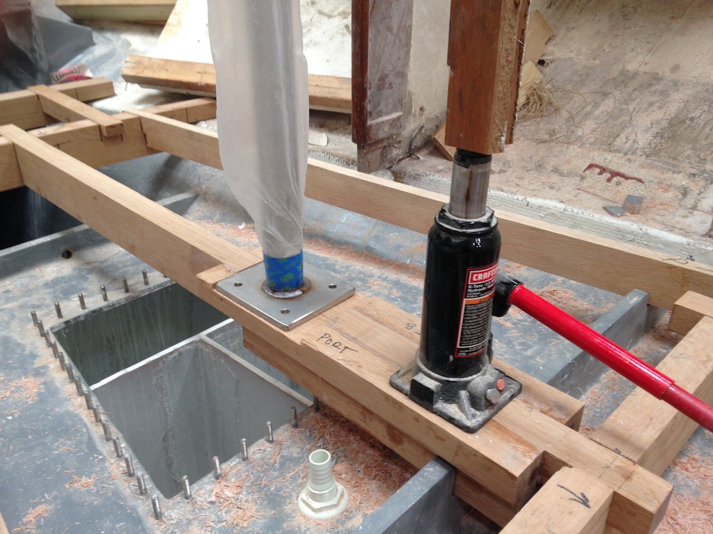
Test fitting the compression post on the beam
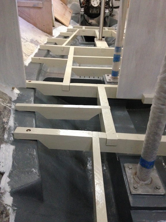
The following photo shows the complete floor-beam assembly, which consists of 24 pieces in all.
The complete floor-beam assembly
The floor beams, test fitted
Next, the floor beams were sanded, primed, then painted. The two-part, white Epoxy Primekote primer was used, followed by one coat of the two-part, cream-colored Interlux Perfection. (Two-part paints and primers aren’t necessary here, but these products had been leftover from previous jobs.)
These floor beams have been primed.
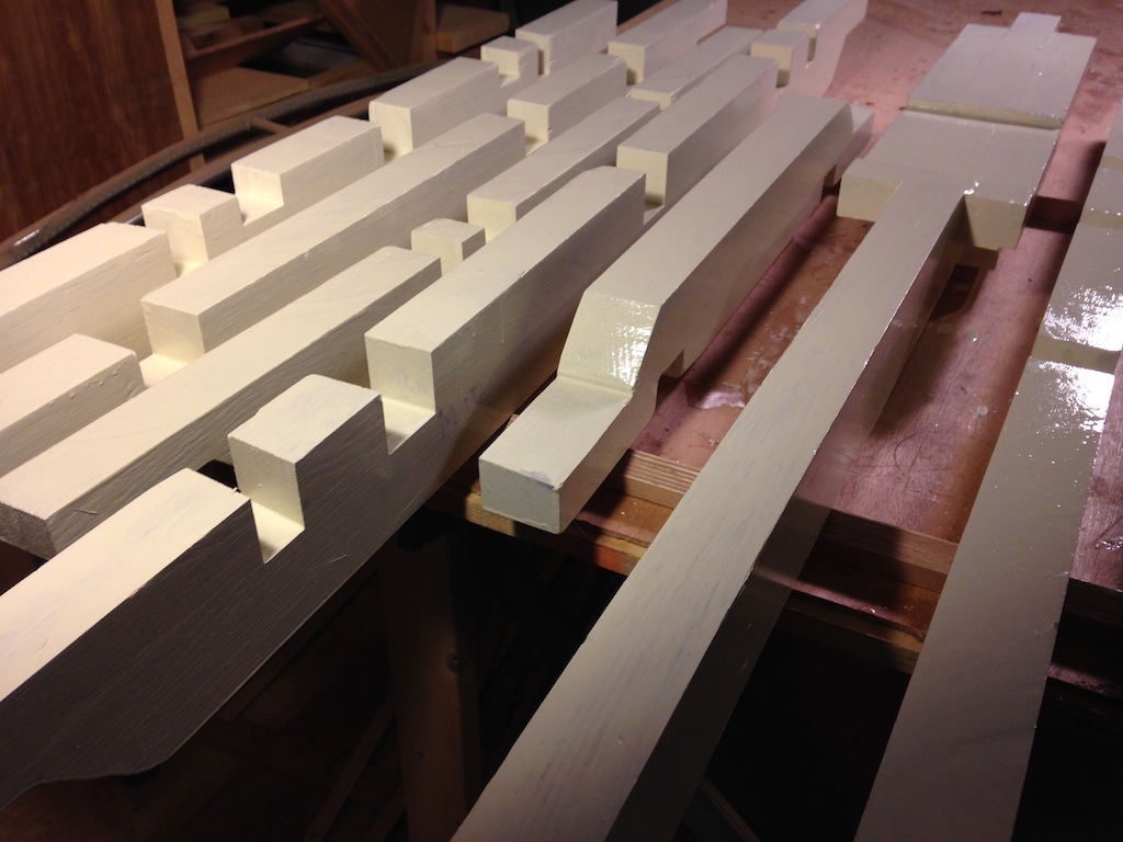
These floor beams have been painted.
Five athwartship floor beams terminate on stringers at each end. These ends were fastened with lag bolts that were recessed to eliminate possible interference with the floor or other furnishings.
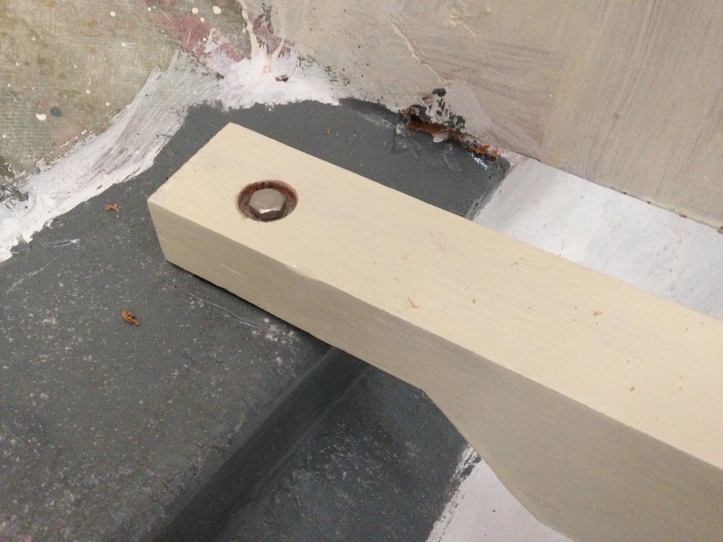
Lag bolts fasten the ends of the long, athwartship beams to the stringers.
Looking aft
The final installation of the aft compression post (Note the beam near the bottom of the photo that is raised at the lap joint. This is not a construction error–the joint isn’t yet fully engaged.)
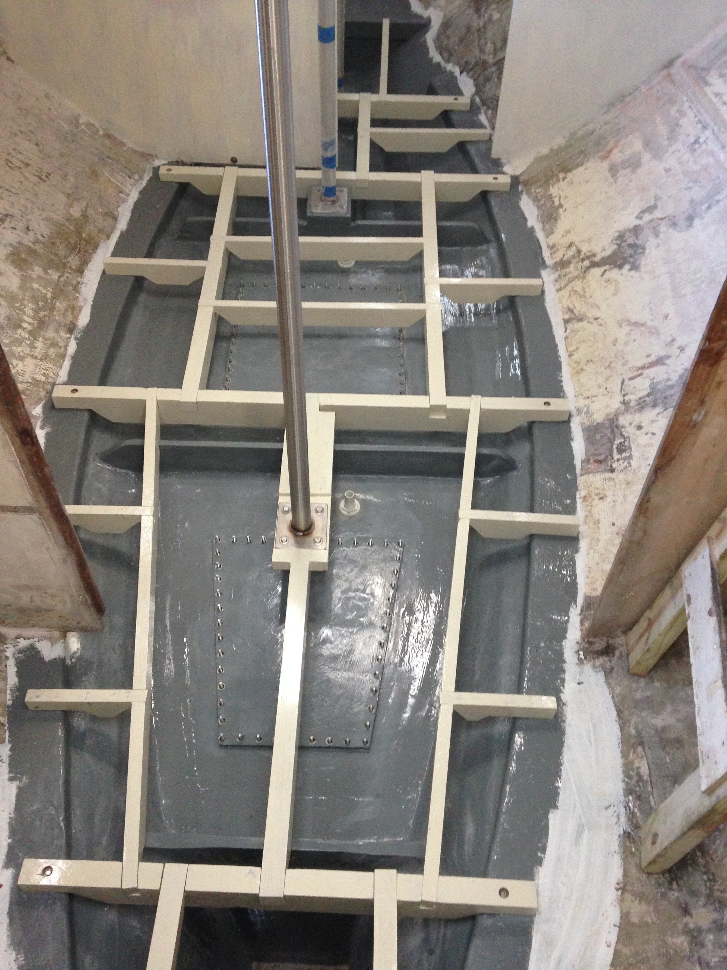
The final layout in the main cabin and galley area
Eventually wood screws will be used at the lap joints to connect the beams to each other. In the mean time, however, a temporary plywood floor will be installed so that work can continue above the bilge areas.
It is interesting to look back to an earlier stage of the project. The photo below was taken from about the same perspective as the photo above, and shows the situation after the bilge area had been completely gutted.