10/7/17: Engine Compartment, Door Openings, Tanks
One of the major upcoming projects will be installing the cabin sole over the floor beams. To do so, however, I need to finish building everything that the floors will butt up against. What is complete already in that regard are the bulkheads, settee fronts, galley fronts, v-berth fronts, holding locker fronts, and head sink-cabinet fronts. (By “fronts” I mean vertical faces of cabinetry and other non-bulkhead furnishings.)
What remains to be built in this regard are the engine enclosure fronts, horizontal members of the door openings, and the front piece below the toilet.
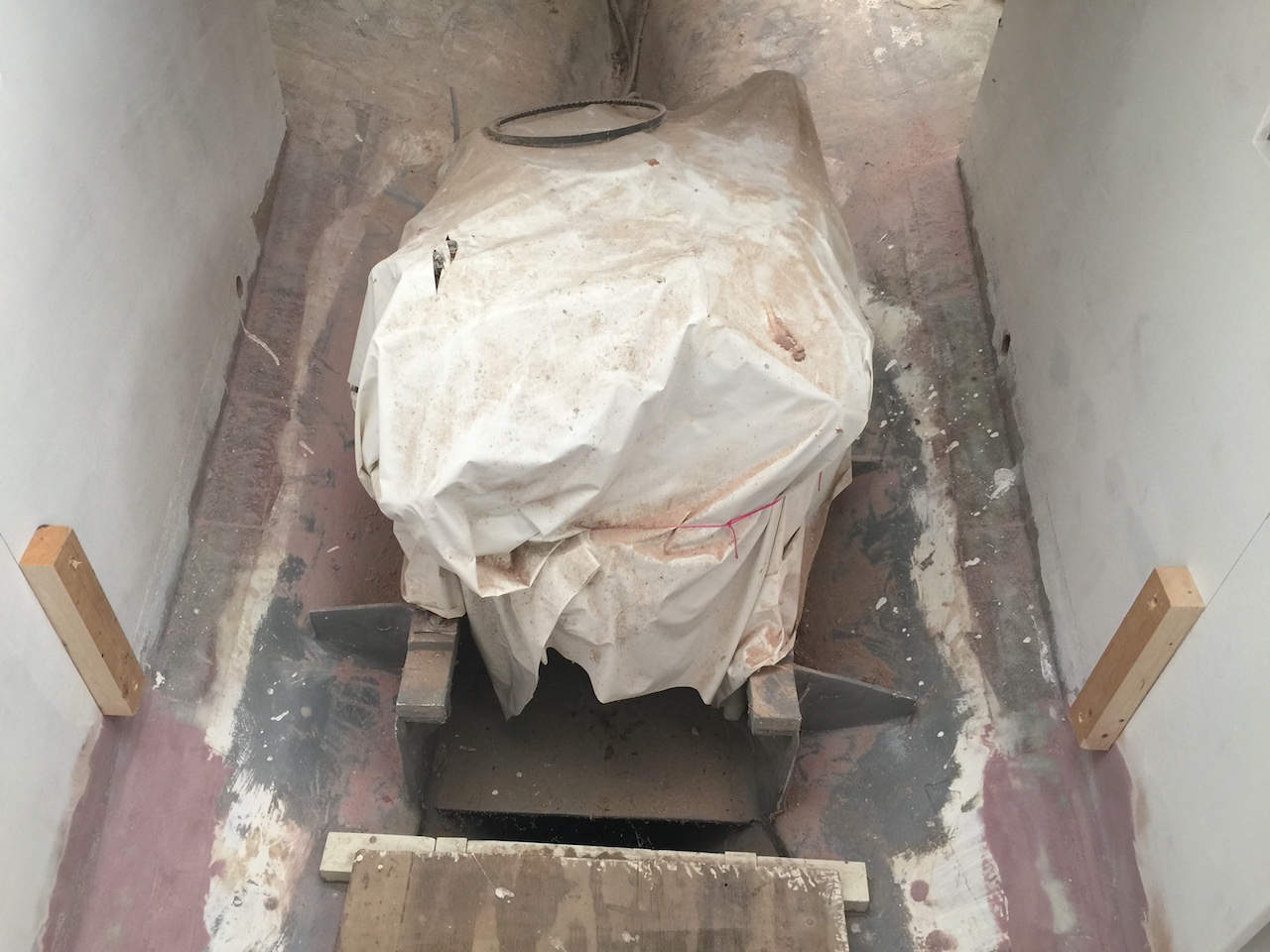
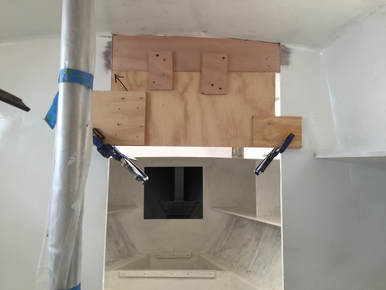
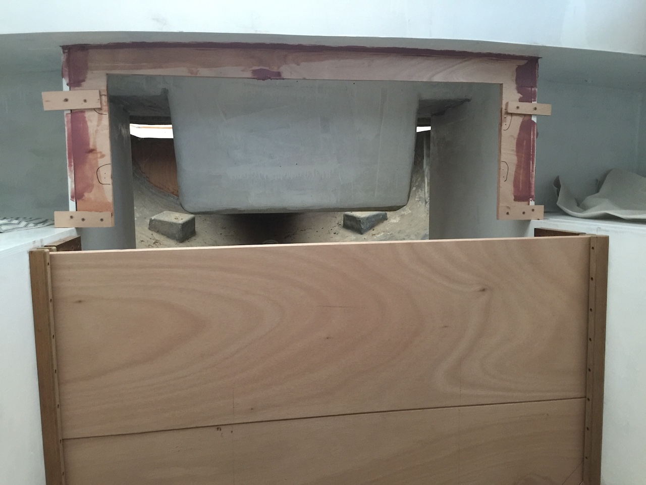
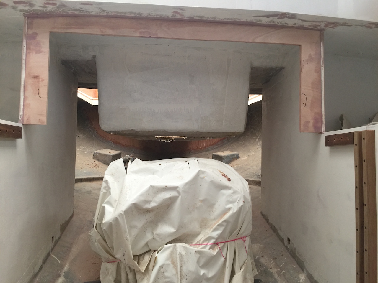
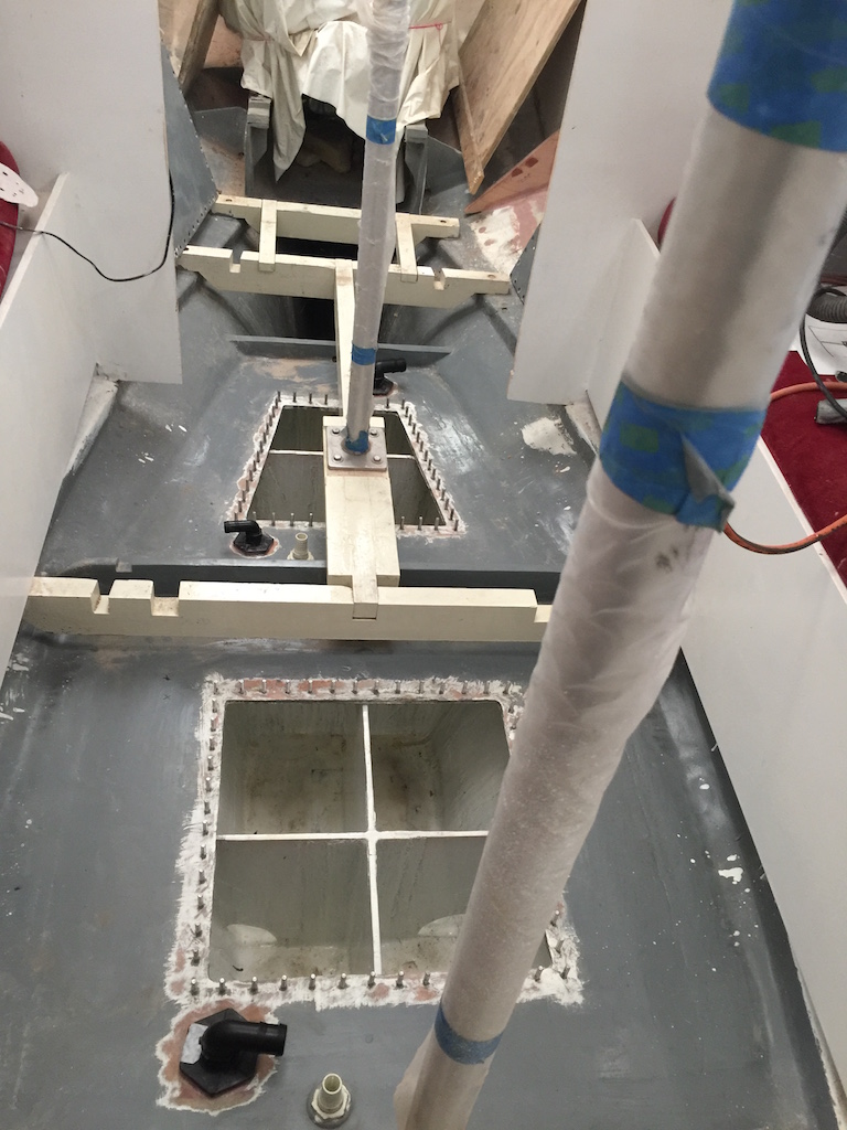
The engine compartment consists of two parallel fore-and-aft bulkheads (see the post on Galley Bulkheads as a refresher) and a cabin-facing enclosure. The following photo shows the engine compartment, where I’ve installed temporary vertical blocks that will define the plane in which defines the front of the enclosure.
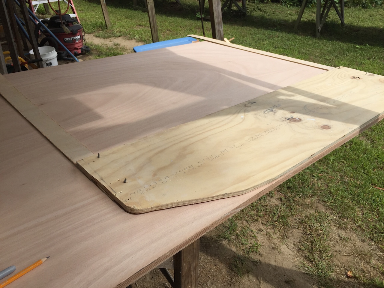
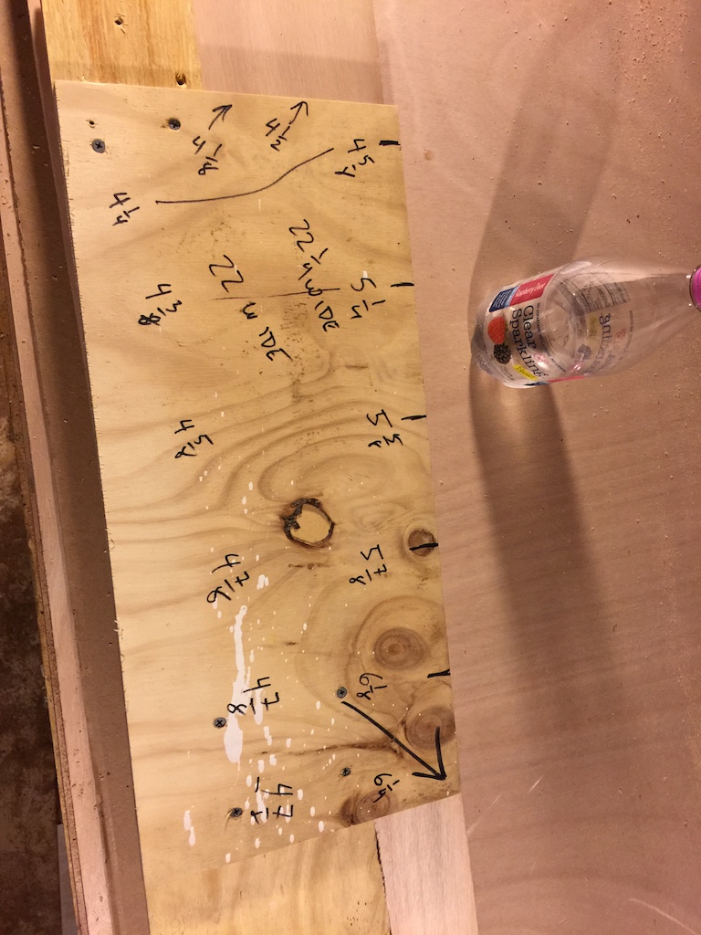
Next, I attached a piece of scrap plywood to the blocks and made some measurements to establish the shape of the hull.
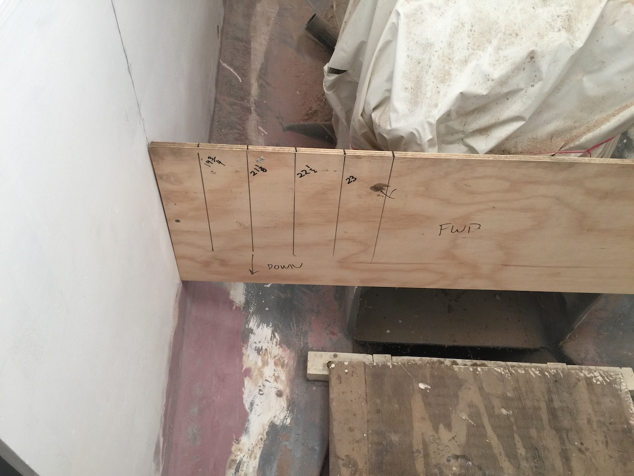
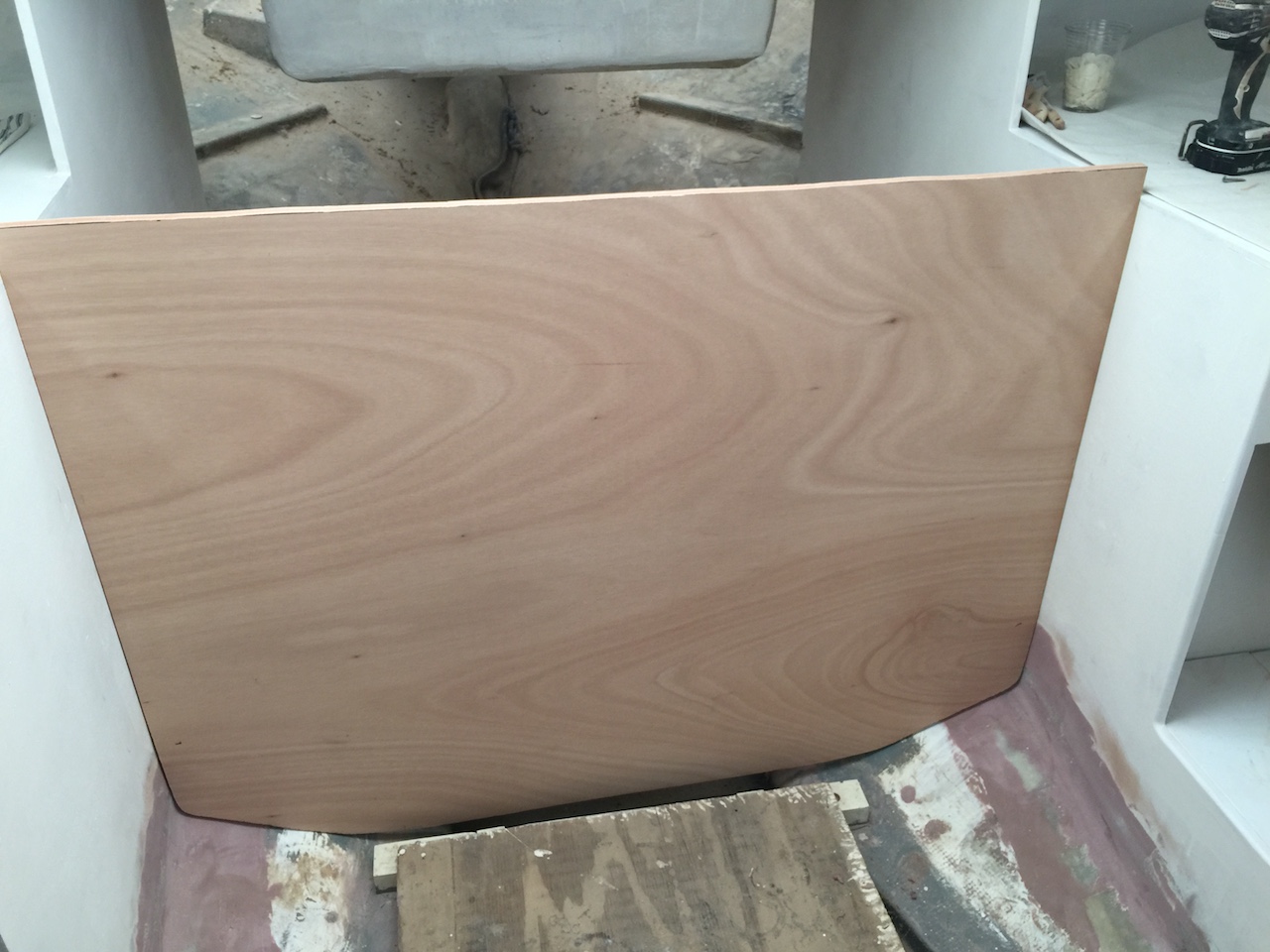
Then I cut the plywood to the shape of the hull, and screwed in some vertical strips to complete the template for the front.
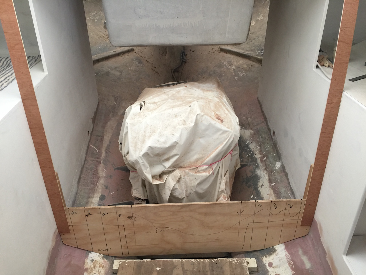
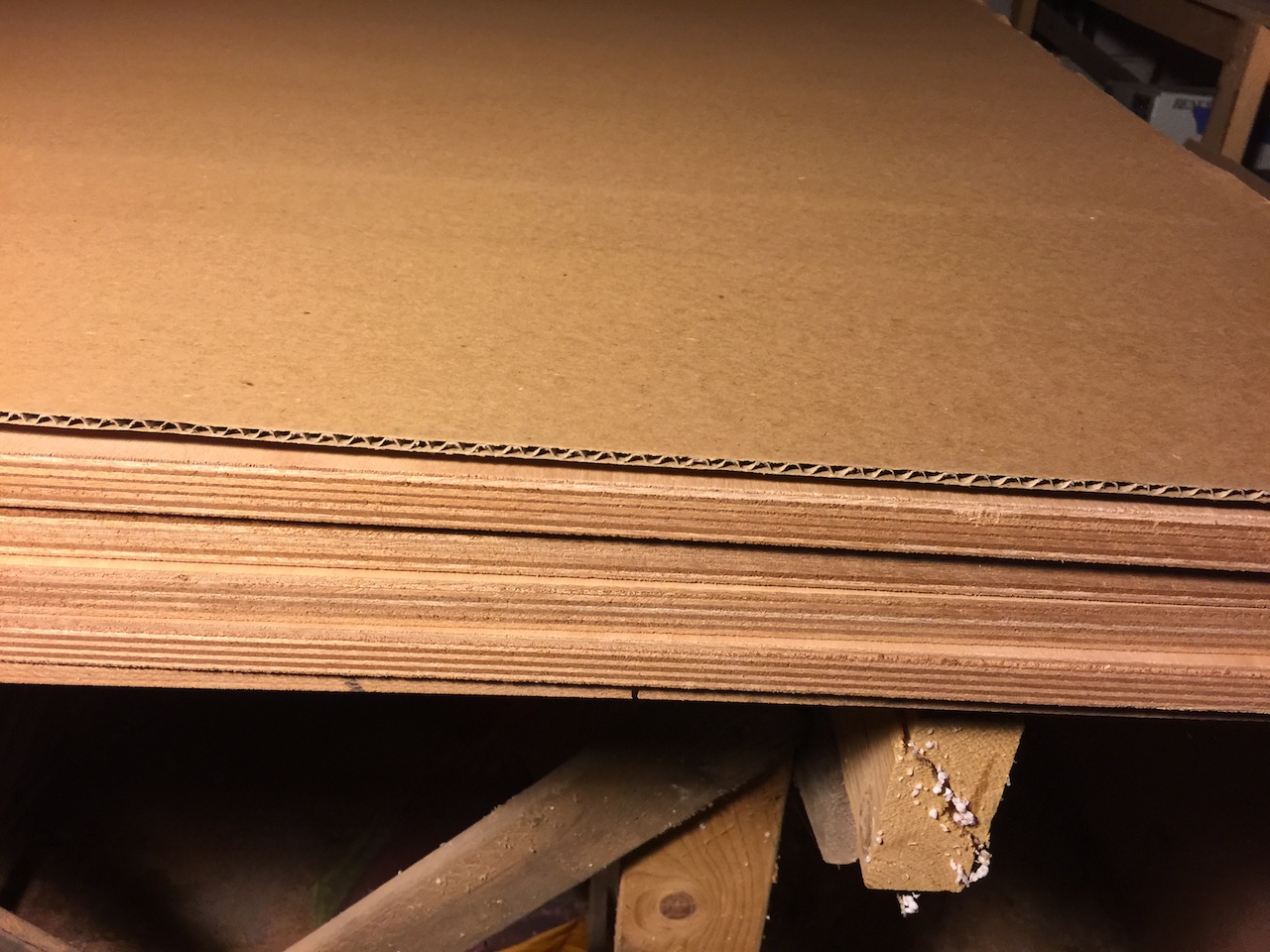
The front will be drop-boards that drop into a slot between teak rails. I decided that the plywood both the cabin sole and the engine enclosure will be the 3/4″ marine variety. The following photo shows four 4×8 sheets on the workshop bench.
This plywood was purchased from Boulter Plywood in Medford MA. There are no local retailers, and I’m sometimes asked why I don’t simply buy what’s available locally. There are a number of reasons, but one problem with anything I’ve found locally (even so-called “marine” grade) is the voids. Plywood consists of a number of veneers that are glued together, with the grain in adjacent layers being in different directions. The result is a strong, dimensionally stable (see definition) material that is easy to work. In the glue, however, there will invariably be bubbles, or gaps where there is no glue, making a void. There can also be imperfections in the veneers that create voids. These voids will appear along the edges of the plywood or wherever the plywood is cut. There are a number of places in the boat where edges of plywood will be finished, so voids would have to be filled.
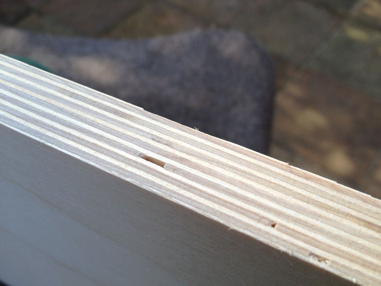
The following photo (not mine) shows the edge of a typical plywood sheet.
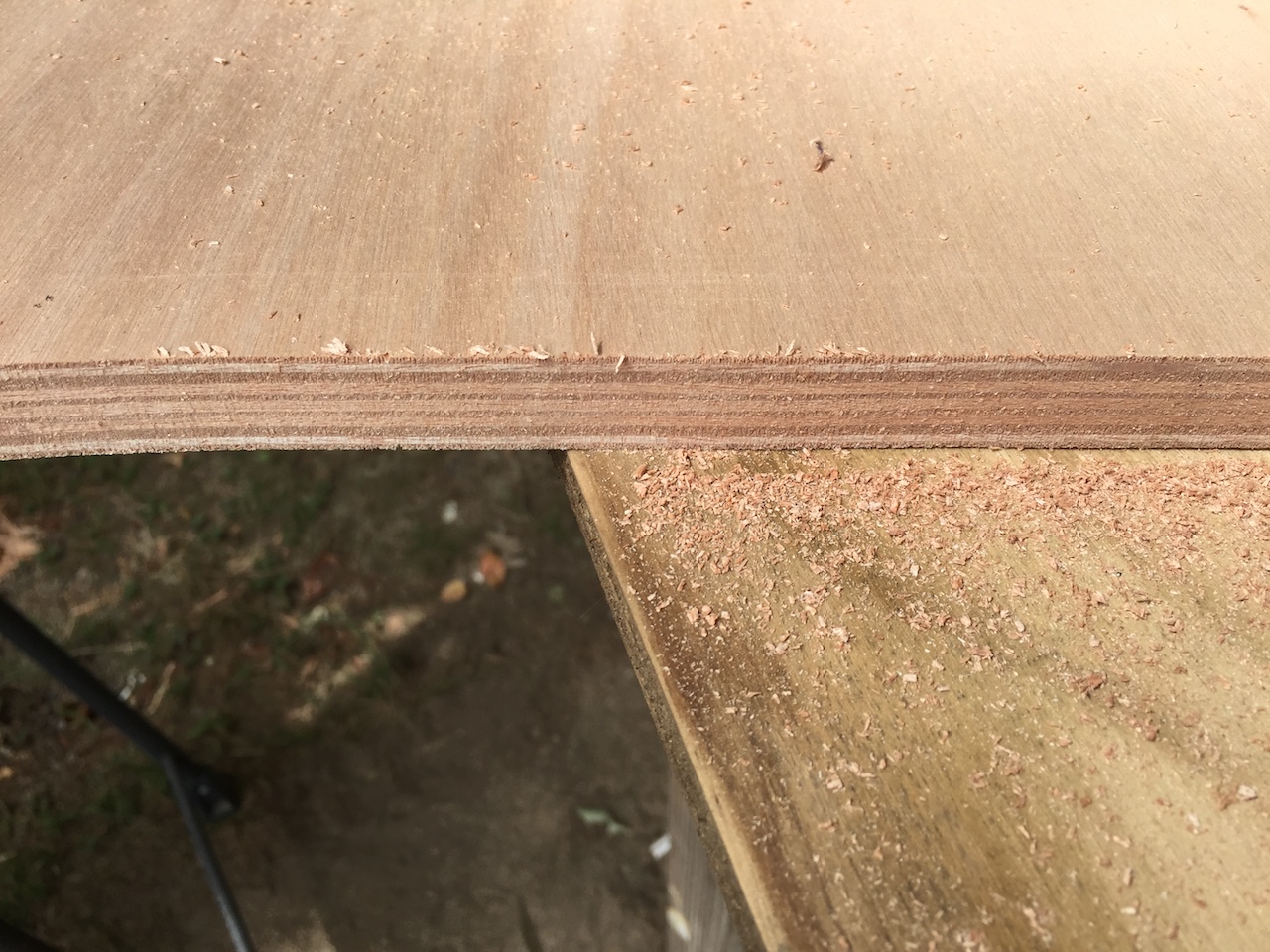
The next photo (mind) shows a cut across the 3/4″ Okume plywood (no voids).
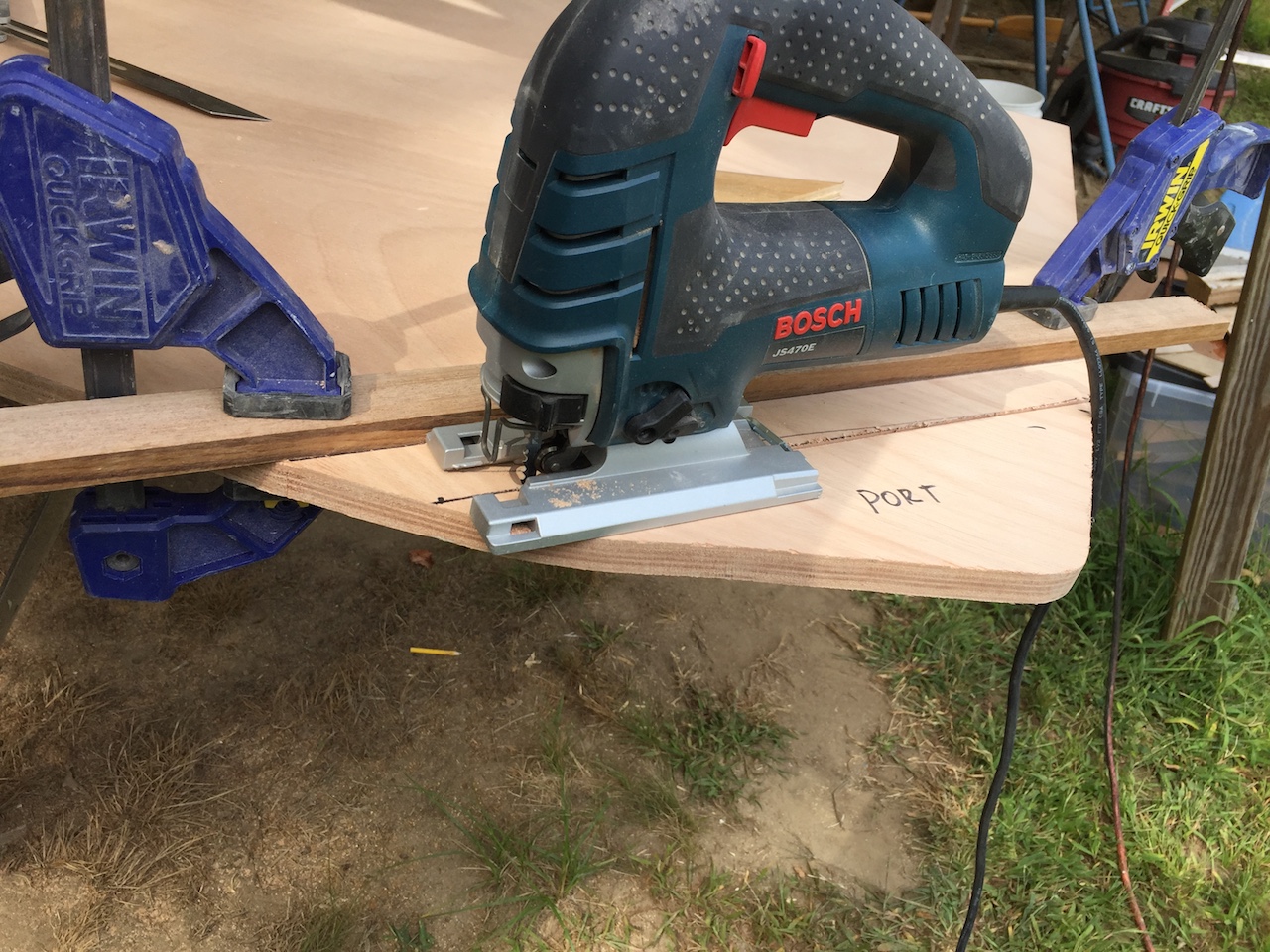
Next, I used the template to cut out the piece for the drop boards.
Here I’ve test-fitted the piece on board.
There will be two drop boards, so this piece will be cut into two smaller pieces. For now, though, I needed to think about how the bottom board would sit on the hull. Considering the curve of the hull and its imperfections in shape, it would be almost impossible to shape the wood to fit snugly along the hull, so I took a different approach.
The following photo shows how I cut the outboard, bottom corners off of the board.
I temporarily reattached these corner pieces.
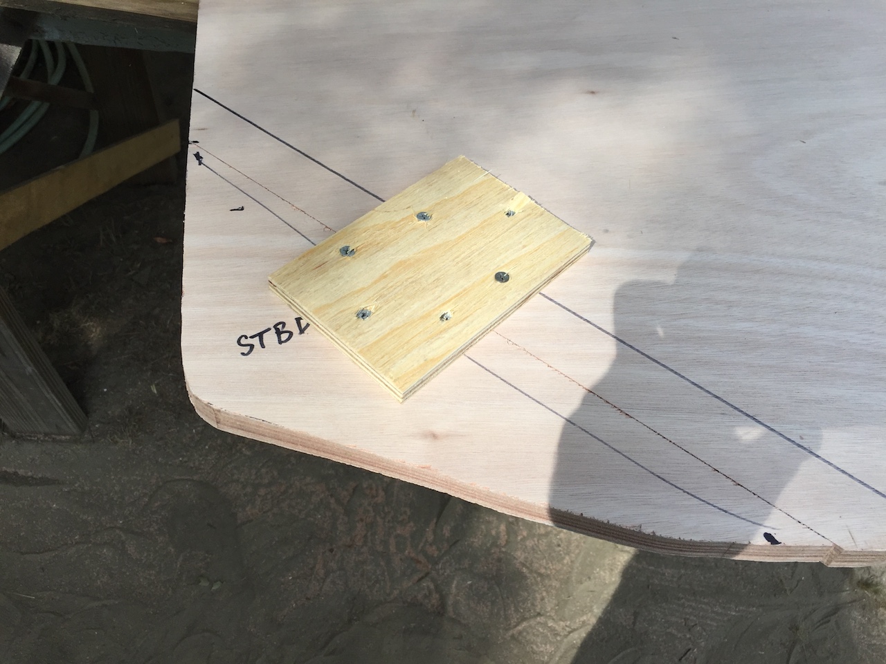
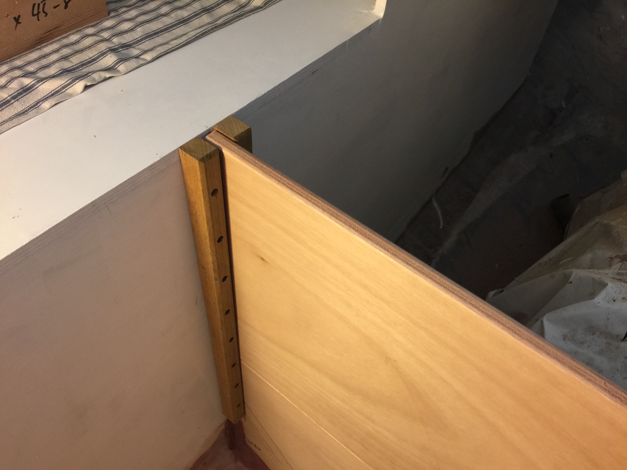
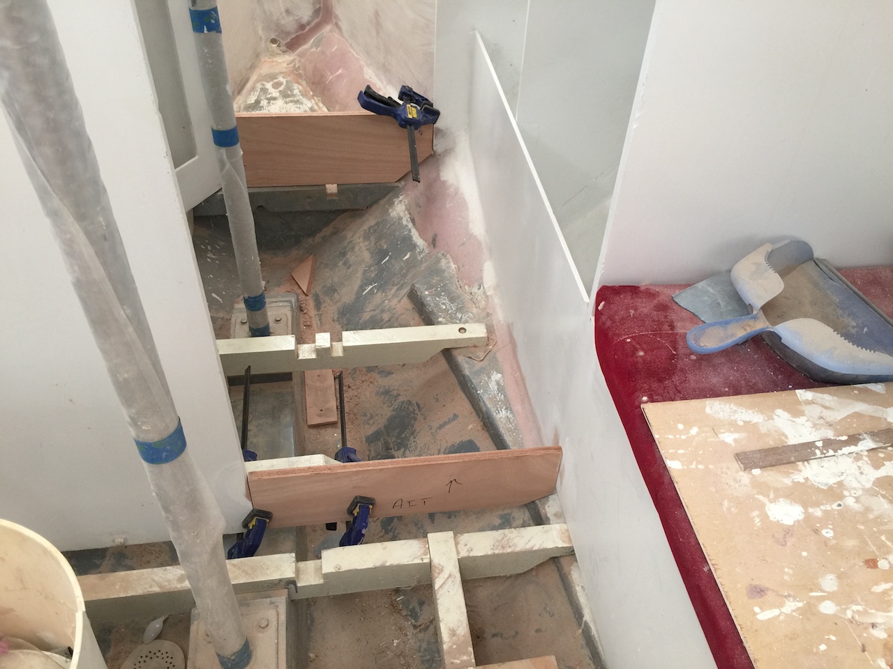
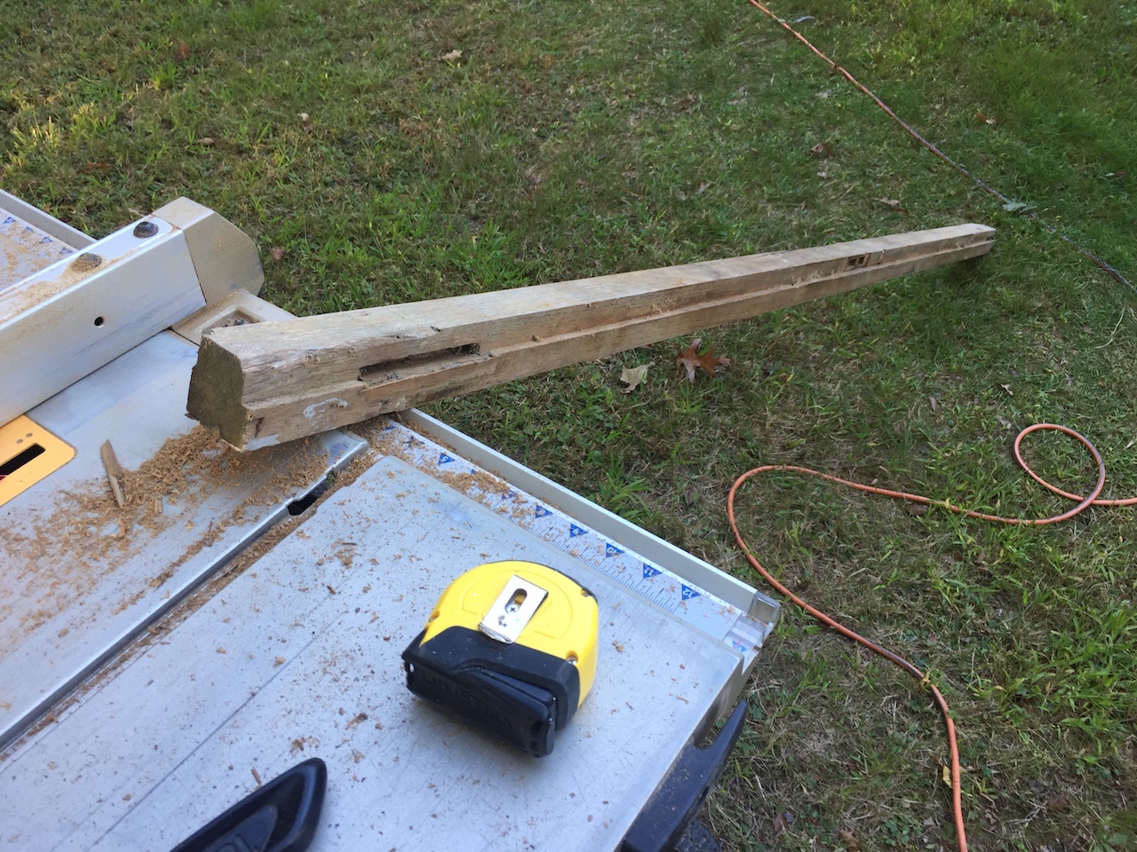
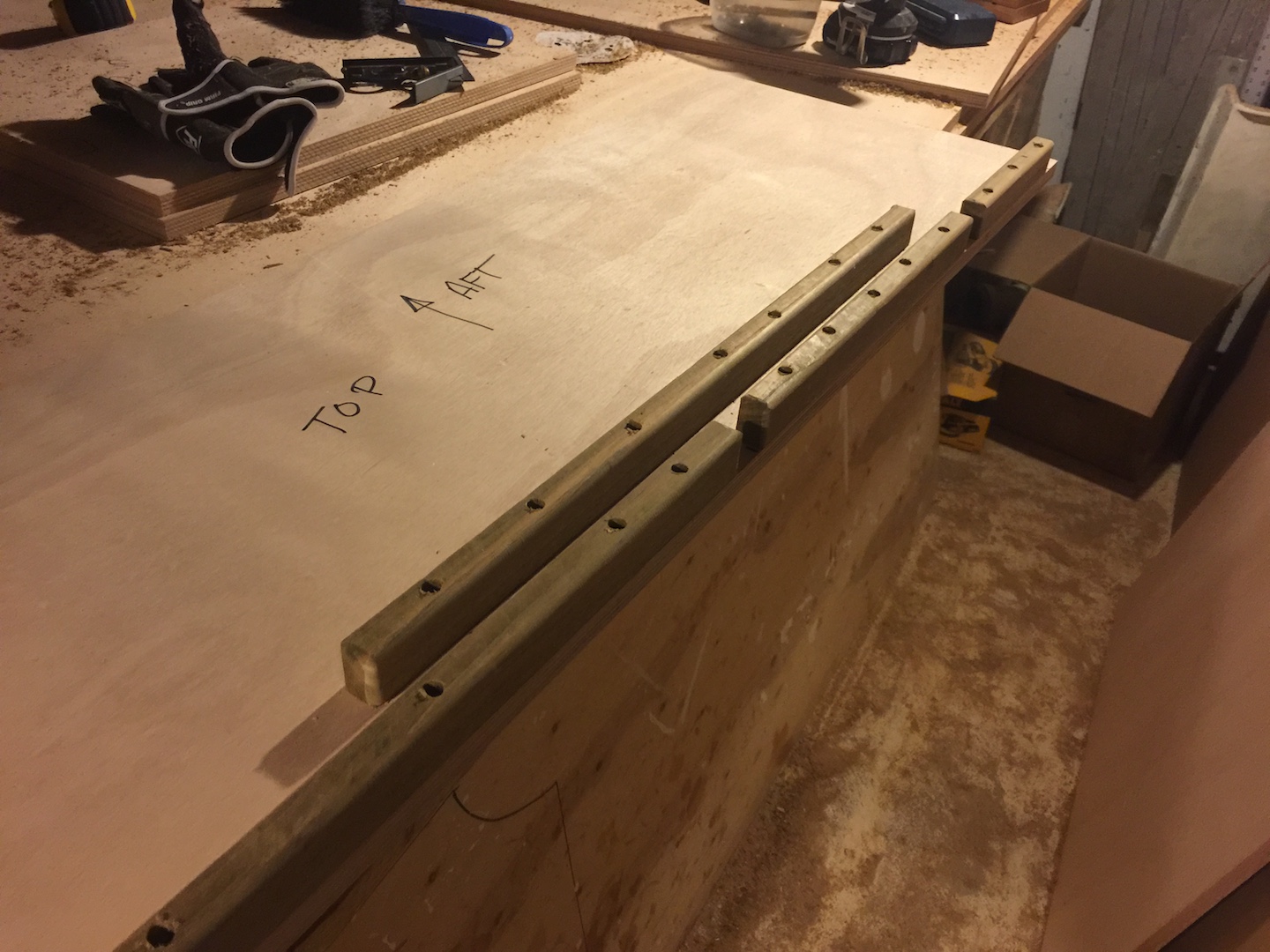
I used some teak from the original head area to fabricate the rails into which the drop boards will slide. Using a scrap piece of the 3/4-inch ply, and a metal square to add about 1/8 inch extra, I set up the rails for temporary attachment.
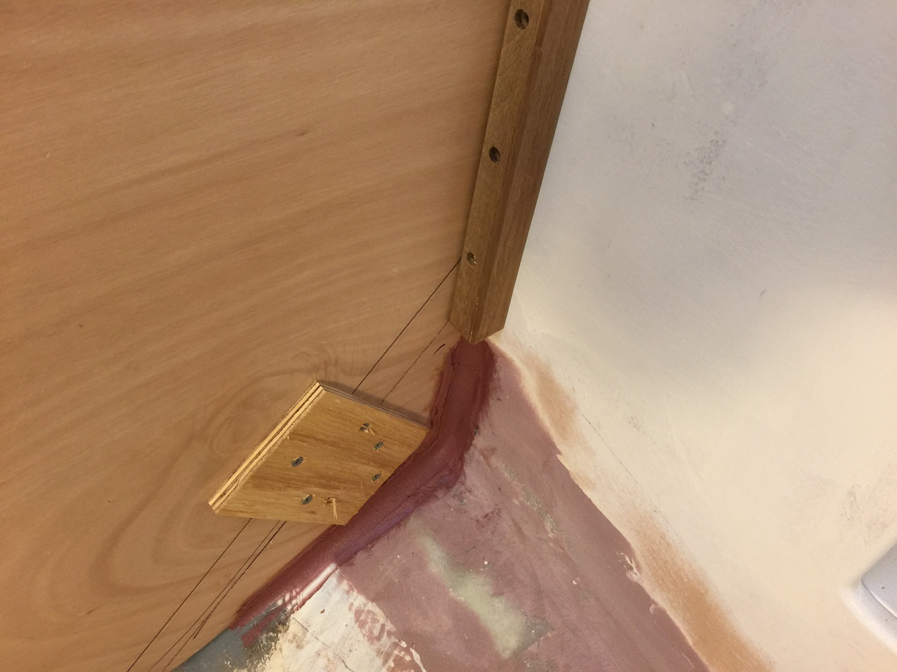
Below we can see where I’ve epoxied the cut corner pieces while they are attached to the whole board. In this way, I am assured a perfect fit for the lower drop board.
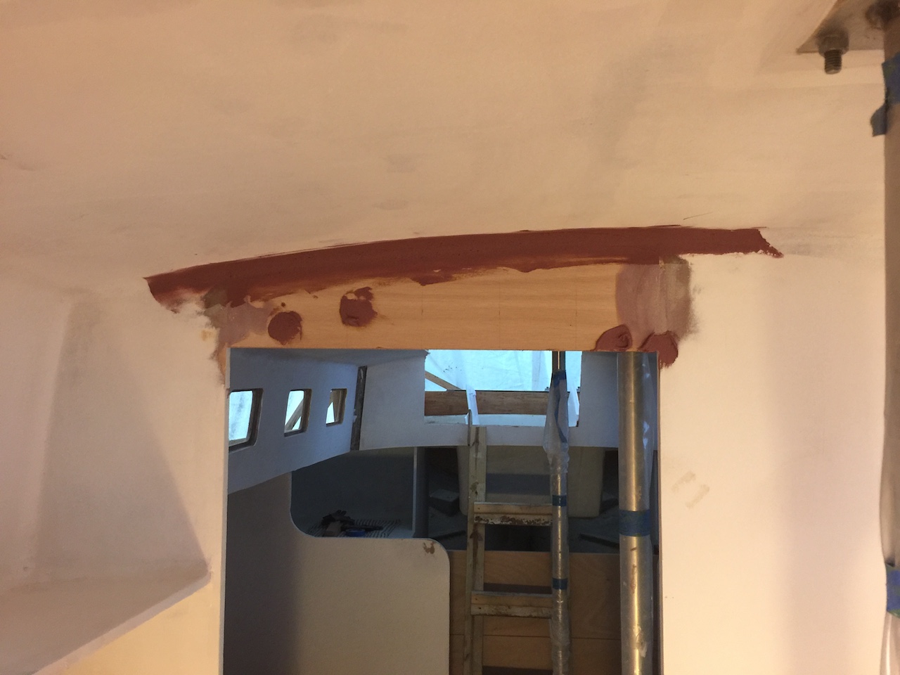
Meanwhile, up forward, I decided on the dimensions of the openings for the doors that lead into the head, and I fabricated some plywood to fill in the top and bottom. What you see below is simply a jig for templating then squaring up the pieces.
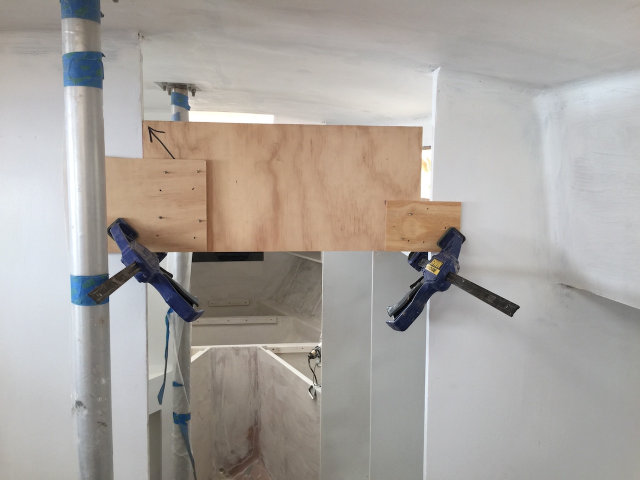
Below we are looking at the opening into the forward cabin, and I’ve temporarily attached the board to the jig.
A similar routine created the pieces that fill in the bottom of the door openings. (In hindsight, this work could have been done in parallel with installing the main structural bulkheads in this area.)
All the gaps were filled and wide fillets of thickened epoxy at the ceiling to match the same on were the bulkheads meet the ceiling.
Back in the galley, I made a template for the upper vertical face of the engine compartment enclosure. This face will contain two doors that will open on hinges. (Note that I’ve cut the lower face in two, so that now that there are two drop boards.)
I used the template to cut out the board, then cut out the two doors from the same panel (not shown). In the image below, I’ve attached the perimeter of this board temporarily and used thickened epoxy to tack it in.
Later, I filled in the remaining gaps and glassed in this piece on the aft side.
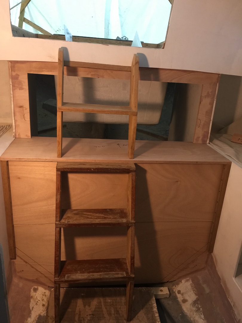
The top of the engine compartment enclosure is a wide, deep, removable shelf that also supports the top part of the two-part companionway ladder. This shelf will rest on the tops of the vertical slides and two horizontal cleats that you can see in the photo above.
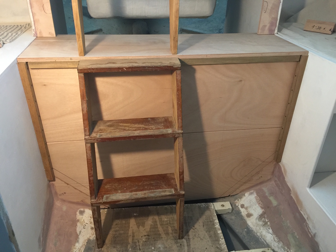
Below I’ve cut out the shelf and set up the companionway ladder temporarily, just to see how everything looks.
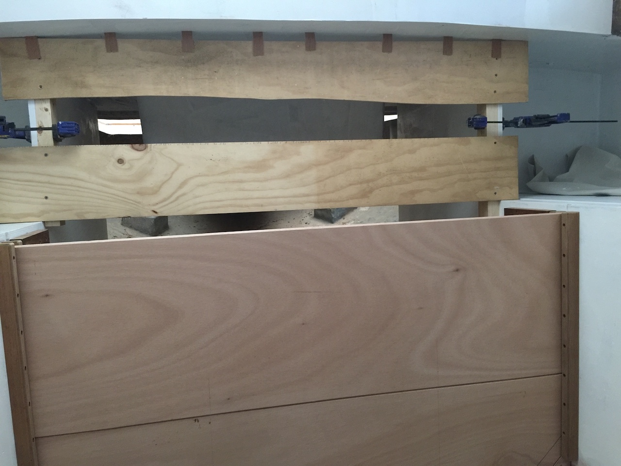
The shelf must be secure and not slide around. I decided to have the forward end of the shelf “grab” the upper drop board. I used more old teak to make more teak rails.
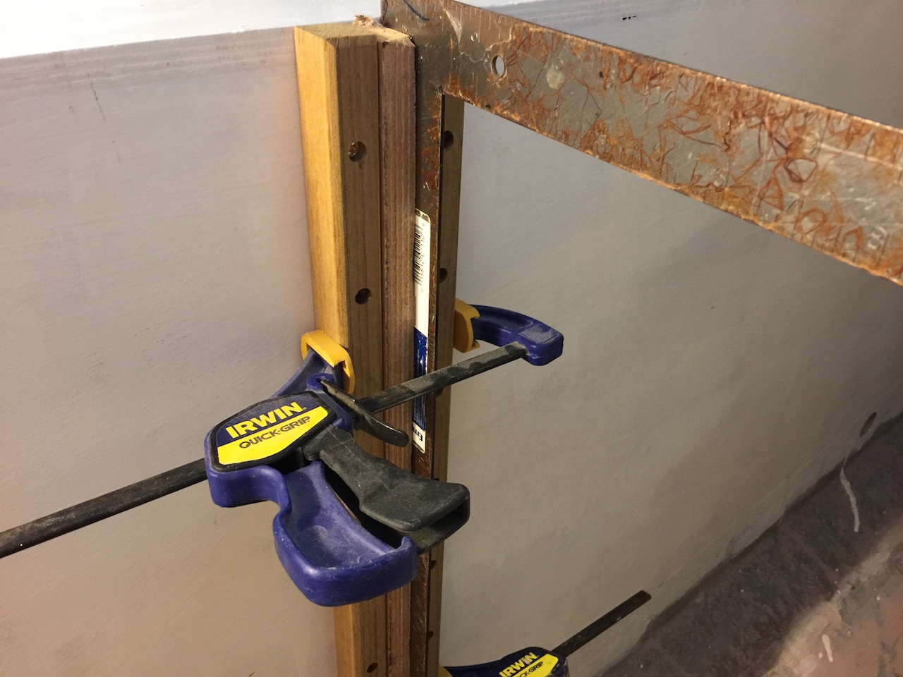
In the photo below I’ve temporarily attached the rails to the underside of the shelf.
The photo below shows everything set up temporarily. There’s still a lot of work to do here.
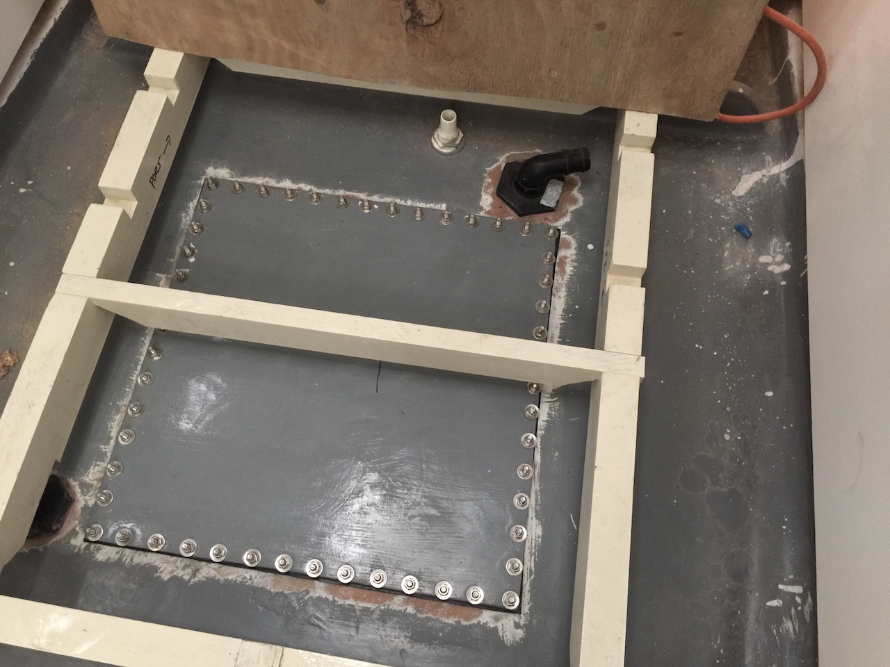
With the sole installation on the horizon, I thought it would be a good idea to finish plumbing the water tanks. The following photo is from 2014 (see THIS POST for a refresher). It shows the two tanks almost ready for their pressure tests. Note that the only plumbing is a 1-inch vent fitting on each tank.
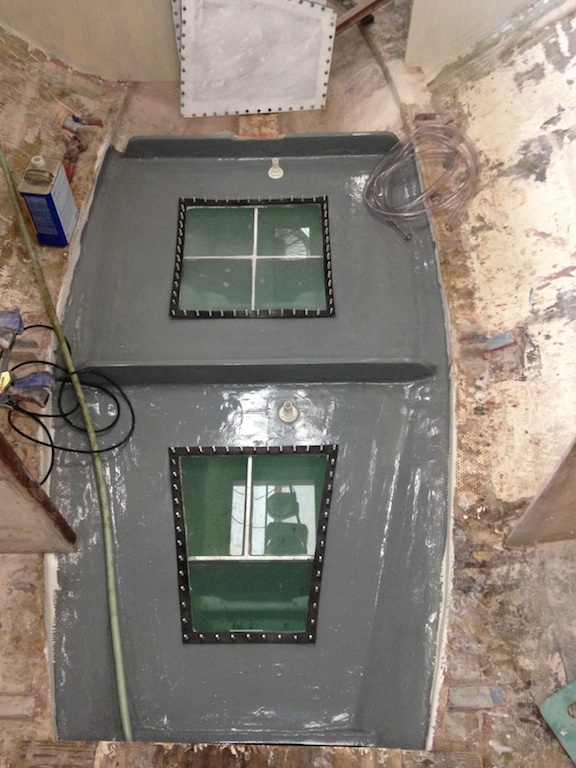
Tanks filled, awaiting pressure testing
The capacity of the aft tank is 75 gallons, while that of the forward tank is 70 gallons. After building the holding tank up in the forward cabin (the later stages of that project can be seen HERE), I though that both of the tanks above would be water tanks. My thinking has changed.
In addition to freshwater and black-water (holding) tanks, many yachts have a so-called “gray water” tank, into which showers sumps, sinks, and ice boxes empty. Gray water is relatively clean, but it will contain detergents, food-related waste, and shower-related runoff. Thus, the ability to prevent gray water from emptying into a harbor is a sensible option. Another advantage of draining gray water into a tank rather than a through-hull is that there is no concern about the sink and icebox being below the waterline when the boat is heeled, and since the tank will pump out through a through-hull shared with the bilge, the total number of through-hull fittings will be reduced by at least two.
After some consideration, I decided that the forward tank (70 gal) will be the gray water tank and the aft tank will be the freshwater tank.
I purchased BANJO BRAND tank fittings for the intake and outtake plumbing.
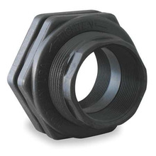
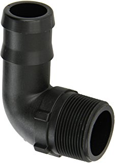
The gray-water tank will have a 1.5-inch pomp-out hose (for fast emptying) and a 1-inch fill hose. The freshwater tank will have a 1.5-inch fill hose (for fast filling) and 1-inch feed hose. I began by drilling holes for the tank fittings.
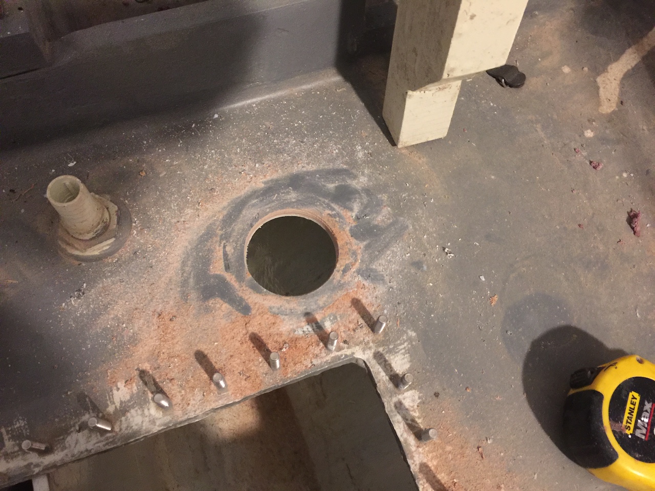
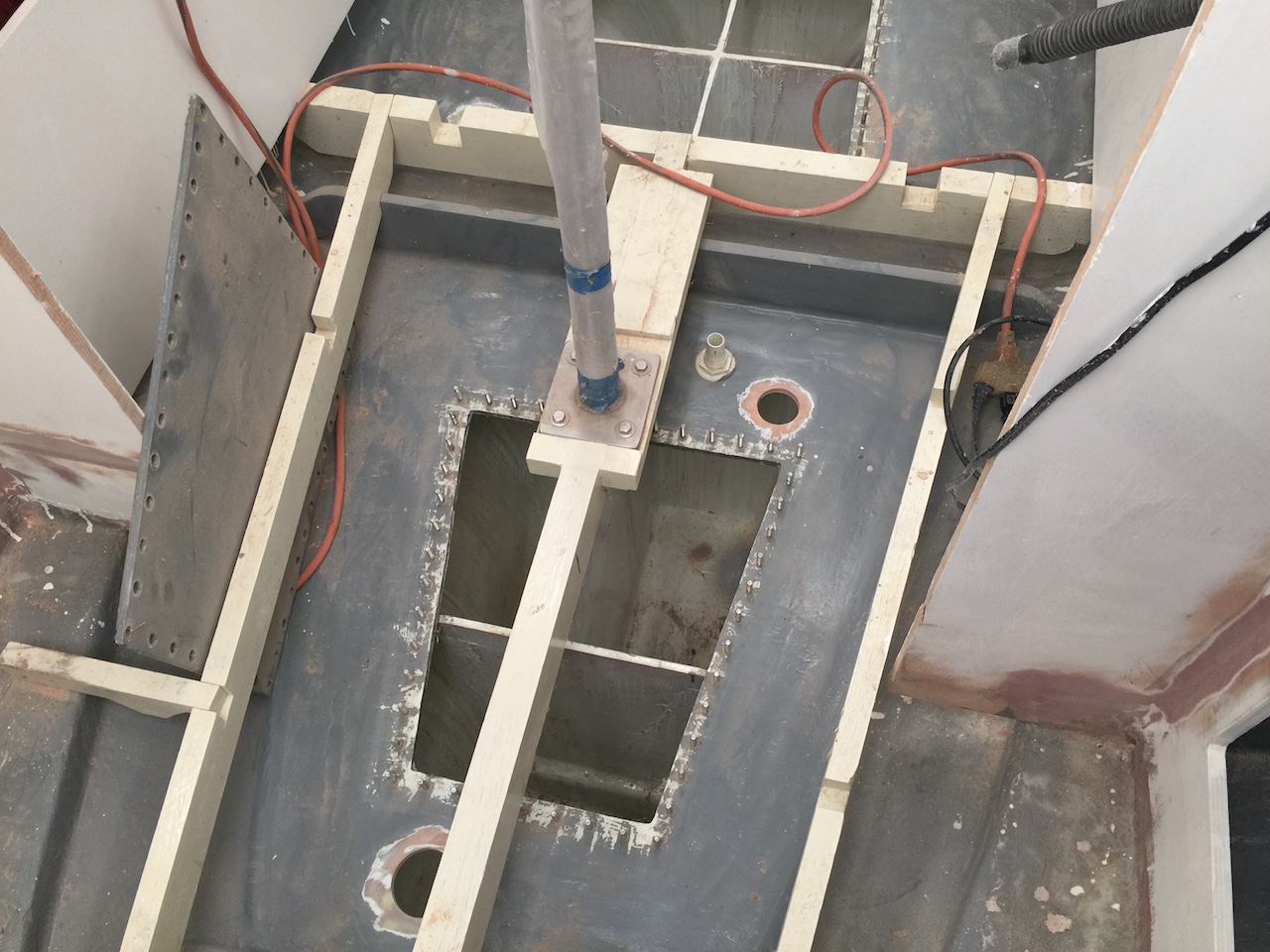
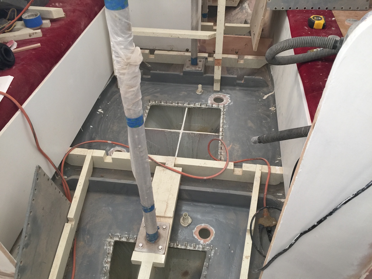
I bedded the fittings in epoxy and connected the barbed hose fittings (angled on the outside, and straight on the inside).
Inside the tanks, I used sanitation hose to draw the fluid from the bottom of the tanks. Eventually, I installed the gaskets and inspection ports.